EP0774935B1 - Vervormbare penisendoprothese - Google Patents
Vervormbare penisendoprothese Download PDFInfo
- Publication number
- EP0774935B1 EP0774935B1 EP95925093A EP95925093A EP0774935B1 EP 0774935 B1 EP0774935 B1 EP 0774935B1 EP 95925093 A EP95925093 A EP 95925093A EP 95925093 A EP95925093 A EP 95925093A EP 0774935 B1 EP0774935 B1 EP 0774935B1
- Authority
- EP
- European Patent Office
- Prior art keywords
- core
- sleeve
- tube
- prosthesis
- outer tube
- Prior art date
- Legal status (The legal status is an assumption and is not a legal conclusion. Google has not performed a legal analysis and makes no representation as to the accuracy of the status listed.)
- Expired - Lifetime
Links
- 239000013536 elastomeric material Substances 0.000 claims abstract description 11
- 238000000034 method Methods 0.000 claims abstract description 11
- 239000000560 biocompatible material Substances 0.000 claims abstract description 5
- 210000005226 corpus cavernosum Anatomy 0.000 claims abstract description 5
- 210000003899 penis Anatomy 0.000 claims abstract description 3
- 229910052751 metal Inorganic materials 0.000 claims description 21
- 239000002184 metal Substances 0.000 claims description 21
- 239000000463 material Substances 0.000 claims description 13
- 230000015572 biosynthetic process Effects 0.000 claims description 7
- -1 polyethylene terephthalate Polymers 0.000 claims description 6
- 239000010935 stainless steel Substances 0.000 claims description 6
- 229910001220 stainless steel Inorganic materials 0.000 claims description 6
- 229920000728 polyester Polymers 0.000 claims description 4
- 229920000139 polyethylene terephthalate Polymers 0.000 claims description 4
- 239000005020 polyethylene terephthalate Substances 0.000 claims description 4
- 229920002379 silicone rubber Polymers 0.000 claims description 4
- 239000004945 silicone rubber Substances 0.000 claims description 4
- 239000007787 solid Substances 0.000 claims description 4
- 238000000748 compression moulding Methods 0.000 claims description 3
- 238000009954 braiding Methods 0.000 claims description 2
- 238000002788 crimping Methods 0.000 claims description 2
- 238000004804 winding Methods 0.000 claims 1
- 238000005452 bending Methods 0.000 description 7
- 239000000853 adhesive Substances 0.000 description 5
- 230000001070 adhesive effect Effects 0.000 description 5
- 229910045601 alloy Inorganic materials 0.000 description 3
- 239000000956 alloy Substances 0.000 description 3
- 150000002739 metals Chemical class 0.000 description 3
- 238000000465 moulding Methods 0.000 description 3
- 230000003993 interaction Effects 0.000 description 2
- 238000004519 manufacturing process Methods 0.000 description 2
- 239000004033 plastic Substances 0.000 description 2
- 229920003023 plastic Polymers 0.000 description 2
- 229920001296 polysiloxane Polymers 0.000 description 2
- 229910052709 silver Inorganic materials 0.000 description 2
- 239000004332 silver Substances 0.000 description 2
- 206010021118 Hypotonia Diseases 0.000 description 1
- 229910001069 Ti alloy Inorganic materials 0.000 description 1
- 229910052782 aluminium Inorganic materials 0.000 description 1
- XAGFODPZIPBFFR-UHFFFAOYSA-N aluminium Chemical compound [Al] XAGFODPZIPBFFR-UHFFFAOYSA-N 0.000 description 1
- 230000000712 assembly Effects 0.000 description 1
- 238000000429 assembly Methods 0.000 description 1
- 239000000969 carrier Substances 0.000 description 1
- VNNRSPGTAMTISX-UHFFFAOYSA-N chromium nickel Chemical compound [Cr].[Ni] VNNRSPGTAMTISX-UHFFFAOYSA-N 0.000 description 1
- 229920001971 elastomer Polymers 0.000 description 1
- 239000000806 elastomer Substances 0.000 description 1
- 208000017561 flaccidity Diseases 0.000 description 1
- 201000001881 impotence Diseases 0.000 description 1
- 238000011065 in-situ storage Methods 0.000 description 1
- 238000003780 insertion Methods 0.000 description 1
- 230000037431 insertion Effects 0.000 description 1
- 230000002452 interceptive effect Effects 0.000 description 1
- 230000018052 penile erection Effects 0.000 description 1
- 229920000642 polymer Polymers 0.000 description 1
- 238000005086 pumping Methods 0.000 description 1
- 239000013464 silicone adhesive Substances 0.000 description 1
- 238000005482 strain hardening Methods 0.000 description 1
- 229910000601 superalloy Inorganic materials 0.000 description 1
- 229910052715 tantalum Inorganic materials 0.000 description 1
- GUVRBAGPIYLISA-UHFFFAOYSA-N tantalum atom Chemical compound [Ta] GUVRBAGPIYLISA-UHFFFAOYSA-N 0.000 description 1
- 229910052720 vanadium Inorganic materials 0.000 description 1
- LEONUFNNVUYDNQ-UHFFFAOYSA-N vanadium atom Chemical compound [V] LEONUFNNVUYDNQ-UHFFFAOYSA-N 0.000 description 1
Images


Classifications
-
- A—HUMAN NECESSITIES
- A61—MEDICAL OR VETERINARY SCIENCE; HYGIENE
- A61F—FILTERS IMPLANTABLE INTO BLOOD VESSELS; PROSTHESES; DEVICES PROVIDING PATENCY TO, OR PREVENTING COLLAPSING OF, TUBULAR STRUCTURES OF THE BODY, e.g. STENTS; ORTHOPAEDIC, NURSING OR CONTRACEPTIVE DEVICES; FOMENTATION; TREATMENT OR PROTECTION OF EYES OR EARS; BANDAGES, DRESSINGS OR ABSORBENT PADS; FIRST-AID KITS
- A61F2/00—Filters implantable into blood vessels; Prostheses, i.e. artificial substitutes or replacements for parts of the body; Appliances for connecting them with the body; Devices providing patency to, or preventing collapsing of, tubular structures of the body, e.g. stents
- A61F2/02—Prostheses implantable into the body
- A61F2/26—Penis implants
-
- Y—GENERAL TAGGING OF NEW TECHNOLOGICAL DEVELOPMENTS; GENERAL TAGGING OF CROSS-SECTIONAL TECHNOLOGIES SPANNING OVER SEVERAL SECTIONS OF THE IPC; TECHNICAL SUBJECTS COVERED BY FORMER USPC CROSS-REFERENCE ART COLLECTIONS [XRACs] AND DIGESTS
- Y10—TECHNICAL SUBJECTS COVERED BY FORMER USPC
- Y10S—TECHNICAL SUBJECTS COVERED BY FORMER USPC CROSS-REFERENCE ART COLLECTIONS [XRACs] AND DIGESTS
- Y10S623/00—Prosthesis, i.e. artificial body members, parts thereof, or aids and accessories therefor
- Y10S623/901—Method of manufacturing prosthetic device
-
- Y—GENERAL TAGGING OF NEW TECHNOLOGICAL DEVELOPMENTS; GENERAL TAGGING OF CROSS-SECTIONAL TECHNOLOGIES SPANNING OVER SEVERAL SECTIONS OF THE IPC; TECHNICAL SUBJECTS COVERED BY FORMER USPC CROSS-REFERENCE ART COLLECTIONS [XRACs] AND DIGESTS
- Y10—TECHNICAL SUBJECTS COVERED BY FORMER USPC
- Y10T—TECHNICAL SUBJECTS COVERED BY FORMER US CLASSIFICATION
- Y10T29/00—Metal working
- Y10T29/49—Method of mechanical manufacture
- Y10T29/49826—Assembling or joining
- Y10T29/49863—Assembling or joining with prestressing of part
- Y10T29/4987—Elastic joining of parts
-
- Y—GENERAL TAGGING OF NEW TECHNOLOGICAL DEVELOPMENTS; GENERAL TAGGING OF CROSS-SECTIONAL TECHNOLOGIES SPANNING OVER SEVERAL SECTIONS OF THE IPC; TECHNICAL SUBJECTS COVERED BY FORMER USPC CROSS-REFERENCE ART COLLECTIONS [XRACs] AND DIGESTS
- Y10—TECHNICAL SUBJECTS COVERED BY FORMER USPC
- Y10T—TECHNICAL SUBJECTS COVERED BY FORMER US CLASSIFICATION
- Y10T29/00—Metal working
- Y10T29/49—Method of mechanical manufacture
- Y10T29/49826—Assembling or joining
- Y10T29/49908—Joining by deforming
- Y10T29/49925—Inward deformation of aperture or hollow body wall
- Y10T29/49927—Hollow body is axially joined cup or tube
-
- Y—GENERAL TAGGING OF NEW TECHNOLOGICAL DEVELOPMENTS; GENERAL TAGGING OF CROSS-SECTIONAL TECHNOLOGIES SPANNING OVER SEVERAL SECTIONS OF THE IPC; TECHNICAL SUBJECTS COVERED BY FORMER USPC CROSS-REFERENCE ART COLLECTIONS [XRACs] AND DIGESTS
- Y10—TECHNICAL SUBJECTS COVERED BY FORMER USPC
- Y10T—TECHNICAL SUBJECTS COVERED BY FORMER US CLASSIFICATION
- Y10T29/00—Metal working
- Y10T29/49—Method of mechanical manufacture
- Y10T29/49826—Assembling or joining
- Y10T29/49947—Assembling or joining by applying separate fastener
- Y10T29/49954—Fastener deformed after application
Definitions
- This invention relates to a malleable penile prosthesis. More particularly, the invention is concerned with a penile prosthesis comprising a malleable core enveloped in a sleeve, which sleeve and core are accommodated within an outer tube of elastomeric material. The invention also relates to a method of making a malleable penile prosthesis. All the materials used in the prosthesis are biocompatible.
- malleable means bendable, with the capacity of holding the resuiting configuration until a subsequent step of bending or straightening is performed.
- the malleable core of the prosthesis of this invention additionally has the characteristic of being substantially rigid when not being subjected to bending, and particularly when in the unbent straight configuration.
- the majority of penile prostheses fall into two types. These two types are the inflatable, implantable prosthesis and the simple implantable inherently stiff or substantially rigid prosthesis.
- the inflatable prosthesis is normally implanted in pairs within the corpora cavernosa and connected to hydraulic pumping means, also implanted within the patient's body, which means enable the prosthesis to be inflated for erection and deflated for flaccidity.
- the simple or non-inflatable, prosthesis is also generally implanted in pairs in the corpora cavernosa and, in view of its inherent stiffness, provides a generally constant erection. Hence, it is desirable to provide positionability so that the erection may be at least partially concealed by the patient. Positionability is generally achieved by making the simple prosthesis bendable or malleable and the prosthesis provided by the present invention is of this simple type, herein designated as a malleable prosthesis.
- Another form of positionable prosthesis comprises an elastomeric rod and a metal wire coil coaxially embedded within at least a portion of the rod, as disclosed in U.S. Patent No. 4,669,456.
- U.S. Patent No. 4,392,562 discloses a limited bend malleable penile prosthesis comprising an elongated malleable element having bend limiting means comprising a plurality of engageable adjacent elements positioned in co-operative juxtaposition with said malleable element.
- U.S. Patent No. 3,987,789 discloses a malleable penile prosthesis comprising an elongated malleable rod portion housed within a generally tubular physiologically inert plastic body; and U.S. Patent No. 4,594,998 (equivalent to EP-A-137752) discloses a similar type of prosthesis but having a somewhat more elaborate and improved structure.
- U.S. Patent No. 4,988,357 discloses a penile prosthesis comprising an implantable flexible rod member formed by a core portion comprising a plurality of metallic wires, typically high-purity silver, and an outer casing comprising implantable plastic material around the core portion.
- an improved malleable penile prosthesis of the type having a malleable core accommodated within a tubular sheath may be provided as hereinafter described, which prosthesis has improved positionability and improved performance.
- a malleable penile prosthesis adapted to be implanted in a corpus cavernosum of a penis, comprising: a elongated core having a distal end and a proximal end and being formed from a plurality of metal wires twisted together ad secured at each of said core distal end and core proximal end with a solid metal tip to form an integral malleable element, said core having a unbent, straight configuration along a longitudinal axis in which configuration it is substantially rigid, and being bendable along said axis with the capability of holding a configuration to which it is bent; a sleeve of braided biocompatible material, having a inner surface and an outer surface, enveloping said core, with the inner surface of the sleeve in contact with the core; and an outer tube of elastomeric material containing the sleeve and the core, said tube having a wall with an outer surface and a inner surface, a distal end
- the sleeve enveloping the core comprises a plurality of layers, preferably three, of braided polymeric material. While the outside diameter of the sleeve is matched with the internal diameter of the outer tube as defined by the crests of the ribs in the inner surface of the wall of the outer tube, there is a small clearance, of the order of 2.5 x 10 -4 to 1.3 x 10 -4 m (0.010 to 0.050 inch), between the outer surface of the sleeve and the surfaces of said crests when the prosthesis is in a straight configuration. The stated surfaces tend to come into contact with each other when the prosthesis is subjected to bending. The small clearance contributes toward positionability without kinking.
- a preferred material for the braided sleeve is a biocompatible polyester, particularly polyethylene terephthalate.
- the invention also provides a method of forming a malleable penile prosthesis comprising an elongated core, a sleeve enveloping said core and an outer tube accommodating said sleeve and core, which method comprises forming said core, enveloping said core with a sleeve of braided biocompatible material, forming a tube of elastomeric material having a wall with a inner surface and an outer surface and a bore defined by the inner surface of the wall, and inserting said sleeve and core within said bore, characterized in that the inner surface has a profile formed of alternate grooves and ribs in a substantially helical arrangement. The crest of each rib is matched closely to the outer surface of the sleeve. The close matching of the outer surface of the sleeve with the inner surface of the outer tube so as to leave a small clearance between said surfaces when the prosthesis is in a straight configuration provides a prosthesis with column strength, positionability and natural feel.
- the elongated core is preferably formed by twisting together a plurality of metal wires, initially positioned in side-by-side longitudinal relationship, to form a substantially rigid but bendable integral bundle having a distal end and a proximal end, and securing the integrity of said core by crimping a solid metal cap to each end of the twisted bundle of metal wires.
- the sleeve of braided material comprises a plurality of layers of braided polymeric material and the sleeve is positioned around the core by braiding the layers, preferably three, tightly around the core to form an integral sleeve in intimate contact with the core.
- the prosthesis of the invention comprises, in combination, a malleable core enveloped in a sleeve of braided material and an outer tube of elastomeric material having an internal surface with a distinctive profile.
- the core is made by twisting together a plurality of metal wires, for example from 100 to 150 wires, each having a diameter of from 1.5 x 10 -4 to 2.5 x 10 -4 m (0.006 to 0.010 inch).
- a particularly preferred embodiment comprise a core made from 134 wires of stainless steel, each having a diameter of about 2 x 10 -4 m (0.008 inch).
- the metal wires are typically made by drawing and usually are of circular cross-section, both for ease of fabrication and interactive contact. However, other configurations, for example, uniform hexagons, are possible, providing the resulting bundle has the required positionability after twisting.
- Twisting of the bundle of wires is necessary to provide positionability without kinking or other distortion and to overcome resistance to bending.
- the proper degree of twisting to achieve optimum positionability and cycle life may be determined by the lay of the wire and is preferably of the order of 0.037 to 0.042 m (1.45 to 1.65 inches).
- Stainless steel is the metal of choice for the wires over other metals or alloys which might be used because it possesses a combination of desirable characteristics.
- silver, tantalum, a alloy of titanium, aluminum and vanadium, and chromium-nickel super alloy which metals and alloys have been suggested for malleable prostheses.
- the preferred twisted wire core described above has better wire-to-wire interaction than previous assemblies incorporating metal wires.
- This, together with increased wire-to-wire contact while maintaining an extended cycle life provides a improved malleable core.
- the malleable core is enveloped in a sleeve of braided material, preferably a biocompatible polyester, such as polyethylene terephthalate.
- the braid is formed from a yam of about 200-250 denier, 50 filament, 2-ply braided on 16 carriers having 1693-1969 picks per m (43-50 picks per inch) with improved tightness over prior braids.
- the sleeve preferably comprises three layers of the braid, and the new sleeve is a distinct improvement over prior art sleeves.
- the core enveloped in the sleeve is accommodated within an outer tube made of elastomeric material, for example, silicone rubber.
- the outer tube has a distal end and a proximal end, each of which has a substantially rounded smooth outer surface.
- the outer tube defines a central longitudinal bore which, to facilitate formation of the prosthesis, initially has a open side port set back from the distal end and is open at the proximal end.
- the proximal open end allows insertion of the core and sleeve therethrough, as well as withdrawal of the groove-forming mandrel, which withdrawal is aided by the open side port, as hereinafter described.
- the open side port and proximal open end are sealed by filling with a silicone adhesive.
- the outer tube has a wall with a substantially smooth outer surface and a inner surface having a profile formed of alternate grooves and ribs in a substantially helical arrangement.
- FIG. 1 of the accompanying drawings illustrates one embodiment of a prosthesis according to the invention.
- the prosthesis comprises a central core 1 extending about the longitudinal was of the prosthesis.
- the core is made from a plurality of metal wires twisted together and secured to form an integral element by metal caps at the distal end 2 and proximal end 3 of the core.
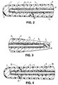
- the metal wire malleable core 1 is enveloped in a sleeve 4 (See Fig. 2, 3 and 4) made up from three layers of braided material, preferably a polyester such as polyethylene terephthalate. As shown in Fig. 7 the three layers 5, 6, 7 of material are braided around the core in situ .
- the core/sleeve combination is accommodated within an elongated outer tube 8 having a substantially rounded smooth surface distal end 9 and a substantially rounded smooth surface proximal end 10.
- the elongated outer tube has a central bore which accommodates the core and sleeve.
- the end of the bore at the proximal end 10 of the tube is open during formation of the prosthesis (as described hereinafter) and is dosed with a plug of adhesive 11, preferably silicone, when the prosthesis is completed.
- the outer surface 12 of the wall of the tube 8 is substantially smooth.
- the outer tube is enveloped in an outer sheath 13 of elastomeric material. This outer sheath is useful for increasing the diameter of the prosthesis.
- the inner surface of the wall of the tube has a profile formed of alternate grooves 14 and ribs 15. There is a small clearance 16 (Fig. 2) between the crest of each rib and the outer surface of the sleeve 4 and this clearance allows bending and straightening of the prosthesis without kinking of the wire bundle while restricting bending to a desirable limit.
- the alternate grooves 14 and ribs 15 are formed in a substantially helical arrangement as illustrated for example in Fig. 6.
- the outer tube 8 is made from a moldable elastomer, for example a silicone rubber, and the groove/rib profile is formed by compression moulding over a pre-formed mandrel at an elevated temperature, for example, about 117°C.
- a moldable elastomer for example a silicone rubber
- the helical grooves are preferably at an angle of about 45° and are formed from a seven start mould mandrel which provides a seven-start structure of helical grooves, which has been found to be the optimum number for longitudinal rigidity and lateral strength.
- the width and depth of the grooves and ribs are balanced so as to provide optimum stiffness and bendability and the helical profile gives a more natural feel to the prosthesis without detracting from the bendability.
- the braided sleeve contributes to the positionability of the malleable core, and the use of three layers in the braid has been found to be enough to contain the wires in the core and to match the outer diameter of the sleeve with the inner diameter of the helix, defined by the crests of the ribs.
- the malleable core is formed by assembling a plurality of metal wires, preferably about 134 wires of stainless steel, each having a diameter of about 2 x 10 -4 m (0.008 inch), side-by-side relationship, forming each end of the wire bundle into a loop 17 to enable the assembly to be connected to a suitable twisting apparatus, for example a lathe, so that the wires may be twisted together.
- a suitable twisting apparatus for example a lathe
- the core is removed from the-sting apparatus, the sleeve is braided around the core and the loops at each end are removed so that each end may be capped to secure the twisted wires.
- the sleeve covered core 1 is then inserted into the central bore of the outer tube through the open end at the proximal end of the tube and the open end is then closed with a plug of adhesive silicone 11 to complete the desired prosthesis.
- FIG. 8 A preferred embodiment of the prosthesis according to the invention is illustrated in Fig. 8.
- the various features are substantially similar to those of the embodiment illustrated in Fig. 1 but the helical arrangement of grooves 18 and ribs 19 is slightly modified.
- the grooves and ribs of the outer tube of the embodiment of Fig. 8 are formed by moulding about a mandrel 20 such as that illustrated in Fig. 9.
- the mandrel comprises an elongated groove and rib forming main portion 21, a distal end portion 22 and a proximal end portion 23.
- the outer tube is formed by compression moulding, at an elevated temperature of a suitable elastomeric polymer, for example, silicone rubber, over the mandrel.
- the moulding operation forms the outer tube with a longitudinal bore which matches the profile of the mandrel wherein the inner surface of the central portion has a helical arrangement of grooves and ribs.
- the moulded tube is provided with a open hole or port 24 in a side wall of the distal portion. In an alternative embodiment, as illustrated in Fig. 4, the hole or port 25 extends diametrically across the tube.
- the bore has an open end 11 at the proximal portion of the tube, formed by the proximal portion 23 of the mandrel.
- a air pipe is attached to the hole 24 or 25 and the bore is distended by air pressure so that the mandrel may be removed through the open proximal end of the bore, and the formed outer tube is then allowed to cool.
- the malleable core and sleeve is then placed in the bore and anchored to prevent internal twisting by adhesive 26 at the distal end and adhesive 27 at the proximal end.
- the holes 24 or 25 at the distal end ad the hole 11 at the proximal end are filled with adhesive to complete the formation of the prosthesis.
Landscapes
- Health & Medical Sciences (AREA)
- Reproductive Health (AREA)
- Cardiology (AREA)
- Oral & Maxillofacial Surgery (AREA)
- Transplantation (AREA)
- Engineering & Computer Science (AREA)
- Biomedical Technology (AREA)
- Heart & Thoracic Surgery (AREA)
- Vascular Medicine (AREA)
- Life Sciences & Earth Sciences (AREA)
- Animal Behavior & Ethology (AREA)
- General Health & Medical Sciences (AREA)
- Public Health (AREA)
- Veterinary Medicine (AREA)
- Prostheses (AREA)
- Orthopedics, Nursing, And Contraception (AREA)
- Materials For Medical Uses (AREA)
Claims (11)
- Verformbare Penisprothese, die in einen Schwellkörper eines Penis implantiert werden kann und folgende Bestandteile umfaßt: einen langgestreckten Kern (1), der ein distales Ende (2) und ein proximales Ende (3) umfaßt und von einer Vielzahl von miteinander verdrillten Metalldrähten gebildet wird, die sowohl am distalen Ende (2) des Kerns als auch am proximalen Ende (3) des Kerns mit einer festen Metallspitze verbunden sind, um ein integrales, verformbares Element zu bilden, wobei der Kern (1) eine nicht gebogene, gerade Konfiguration längs einer Längsachse aufweist und in dieser Konfiguration im wesentlichen steif ist, sowie längs dieser Achse gebogen werden kann, wobei er die Fähigkeit besitzt, eine Konfiguration beizubehalten, in der er gebogen ist, eine Hülle (4) aus geflochtenem, körperverträglichen Material, die eine innere Oberfläche und eine äußere Oberfläche besitzt und den Kern (1) umhüllt, wobei die innere Oberfläche der Hülle (4) in Berührung mit dem Kern (1) steht, und ein äußeres Rohr (8) aus einem elastomeren Material, das die Hülle (4) und den Kern (1) enthält, wobei das Rohr (8) eine Wand mit einer äußeren Oberfläche und einer inneren Oberfläche, ein distales Ende (9) und ein proximales Ende (10) besitzt, wobei jedes dieser Enden (9, 10) eine im wesentlichen abgerundete, glatte äußere Oberfläche besitzt, und wobei die äußere Oberfläche der Wand im wesentlichen glatt ist, dadurch gekennzeichnet, daß die innere Oberfläche der Wand des Rohrs (8) ein Profil besitzt, das aus abwechselnden Rillen (14) und Rippen (15) in einer im wesentlichen schraubenförmigen Anordnung gebildet ist.
- Prothese nach Anspruch 1, dadurch gekennzeichnet, daß die Hülle (4) eine Vielzahl von Schichten aus einem geflochtenen, polimeren Material besitzt und einen Außendurchmesser aufweist, der zu einem Innendurchmesser paßt, der von den Scheiteln der Rippen (15) in dem äußeren Rohr (8) definiert wird, wobei diese Scheitel Oberflächen besitzen und ein kleiner Freiraum zwischen der äußeren Oberfläche der Hülle (4) und den Oberflächen der Scheitel vorgesehen ist, wenn sich die Prothese in ihrer geraden Konfiguration befindet.
- Prothese nach Anspruch 1 oder 2,dadurch gekennzeichnet, daß der Kern (1) ungefähr 100 bis 150 Drähte aus Edelstahl umfaßt, von denen jeder einen Durchmesser von ungefähr 1,5x10⁻⁴ bis 2,5x10⁻⁴ m aufweist und die miteinander verdrillt und von einer Hülle (4) umhüllt sind, die wenigstens drei Schichten aus geflochtenem Polyester umfaßt.
- Prothese nach einem der vorhergehenden Ansprüche, dadurch gekennzeichnet, daß die Rillen (14) in der inneren Oberfläche der Wand des äußeren Rohrs (8) von einer 7-zügigen Struktur aus schraubenförmigen Rillen gebildet wird, die einen Steigungswinkel von ungefähr 45° besitzen, und daß das elastomere Material des Rohrs (8) ein Silicongummi ist.
- Prothese nach einem der vorhergehenden Ansprüche, dadurch gekennzeichnet, daß eine äußere Umhüllung (13) das äußere Rohr (8) umgibt.
- Verfahren zur Herstellung einer verformbaren Penisprothese, die einen langgestreckten Kern (1), eine Hülle (4), die den Kern (1) umgibt, und ein äußeres Rohr (8) umfaßt, das die Hülle (4) und den Kern (1) aufnimmt, wobei das Verfahren folgende Schritte umfaßt: Ausbilden des Kerns (1); Umgeben des Kerns (1) mit einer Hülle (4) aus geflochtenem, körperverträglichen Material; Ausbilden eines Rohrs (8) aus elastomerem Material, das eine Wand mit einer inneren Oberfläche und einer äußeren Oberfläche sowie eine durch die innere Oberfläche der Wand umschlossene Bohrung aufweist; Einführen der Hülle (4) und des Kerns (1) in die Bohrung, dadurch gekennzeichnet, daß die innere Oberfläche der Wand des Rohrs (8) ein Profil besitzt, das von alternierenden Rillen (14) und Rippen (15) in einer im wesentlichen schraubenförmigen Anordnung gebildet wird.
- Verfahren nach Anspruch 6, dadurch gekennzeichnet, daß der langgestreckte Kern (1) dadurch gebildet wird, daß eine Vielzahl von Metalldrähten, die zunächst Seite an Seite nebeneinander angeordnet sind, miteinander verdrillt werden, um ein im wesentlichen steifes, biegbares, integrales Bündel mit einem distalen Ende (2) und einem proximalen Ende (3) zu bilden, und daß die Einstückigkeit dieses Bündes dadurch gesichert wird, daß eine feste Metallkappe auf jedes Ende (2, 3) des Bündels aufgequetscht wird.
- Verfahren nach Anspruch 6 oder 7, dadurch gekennzeichnet, daß eine Hülle (4), die eine Vielzahl von Schichten aus geflochtenem, polimeren Material umfaßt, dadurch um den Kern (1) angeordnet wird, daß die Schichten straff um den Kern (1) herumgewickelt werden, um eine integrale Hülle (4) in engem Kontakt mit dem Kern (1) zu bilden.
- Verfahren nach einem der Ansprüche 6 bis 8,dadurch gekennzeichnet, daß der Kern (1) aus Drähten aus Edelstahl hergestellt ist und daß die Hülle (4) dadurch gebildet wird, daß drei Lagen aus Polyethylenterephtalat-Garn um den Kern (1) herumgeflochten werden.
- Verfahren nach einem der Ansprüche 6 bis 9, dadurch gekennzeichnet, daß die Bohrung des äußeren Rohrs (8) durch Formpressen des Materials des Rohrs um einen vorgeformten Dom (20) bei erhöhter Temperatur, Ausweiten der Bohrung mit Hilfe von Druckluft, die durch ein Loch im distalen Teil des Rohrs (8) zugeführt wird, und damit verbundenes Entfernen des Doms (20) und Abkühlenlassen des sich ergebenden, geformten Produkts gebildet wird.
- Verfahren nach einem der Ansprüche 6 bis 10, dadurch gekennzeichnet, daß der Außendurchmesser der Prothese dadurch vergrößert wird, daß das äußere Rohr (8) mit einer Umhüllung (13) aus einem elastomeren Material umgeben wird.
Applications Claiming Priority (3)
| Application Number | Priority Date | Filing Date | Title |
|---|---|---|---|
| US08/287,439 US5512033A (en) | 1994-08-08 | 1994-08-08 | Malleable penile prosthesis |
| US287439 | 1994-08-08 | ||
| PCT/IB1995/000596 WO1996004865A1 (en) | 1994-08-08 | 1995-07-31 | Malleable penile prosthesis |
Publications (2)
| Publication Number | Publication Date |
|---|---|
| EP0774935A1 EP0774935A1 (de) | 1997-05-28 |
| EP0774935B1 true EP0774935B1 (de) | 1999-11-03 |
Family
ID=23102917
Family Applications (1)
| Application Number | Title | Priority Date | Filing Date |
|---|---|---|---|
| EP95925093A Expired - Lifetime EP0774935B1 (de) | 1994-08-08 | 1995-07-31 | Vervormbare penisendoprothese |
Country Status (10)
| Country | Link |
|---|---|
| US (2) | US5512033A (de) |
| EP (1) | EP0774935B1 (de) |
| JP (1) | JP3009226B2 (de) |
| AT (1) | ATE186194T1 (de) |
| AU (1) | AU683399B2 (de) |
| CA (1) | CA2195215C (de) |
| DE (1) | DE69513181T2 (de) |
| ES (1) | ES2141364T3 (de) |
| MX (1) | MX9701008A (de) |
| WO (1) | WO1996004865A1 (de) |
Cited By (8)
| Publication number | Priority date | Publication date | Assignee | Title |
|---|---|---|---|---|
| US8052594B2 (en) | 2007-11-20 | 2011-11-08 | Ams Research Corporation | Prosthetic device with protrusions for girth |
| US8052593B2 (en) | 2006-10-24 | 2011-11-08 | Ams Research Corporation | Implantable malleable penile prosthetic device |
| US8114011B2 (en) | 2007-10-23 | 2012-02-14 | Ams Research Corporation | Corrugated inflatable penile prosthesis cylinder |
| US8123674B2 (en) | 2007-11-12 | 2012-02-28 | Ams Research Corporation | Corrugated expansion-constraining sleeve for an inflatable penile prosthesis cylinder |
| US8911350B2 (en) | 2007-10-23 | 2014-12-16 | Ams Research Corporation | Malleable prosthesis with enhanced concealability |
| US9801702B2 (en) | 2010-12-16 | 2017-10-31 | Boston Scientific Scimed, Inc. | Artificial sphincter system and method |
| US10070955B2 (en) | 2007-11-15 | 2018-09-11 | Boston Scientific Scimed, Inc. | Prosthesis with bendable central region |
| US10952855B2 (en) | 2016-03-24 | 2021-03-23 | Boston Scientific Scimed, Inc. | Inflatable penile prosthesis with reversible flow pump assembly |
Families Citing this family (26)
| Publication number | Priority date | Publication date | Assignee | Title |
|---|---|---|---|---|
| US6651670B2 (en) | 1998-02-13 | 2003-11-25 | Ventrica, Inc. | Delivering a conduit into a heart wall to place a coronary vessel in communication with a heart chamber and removing tissue from the vessel or heart wall to facilitate such communication |
| DE69923674T2 (de) * | 1998-05-21 | 2005-12-29 | Children's Medical Center Corp., Boston | Penisrekonstruktion mit hilfe von körpergewebe |
| US7578828B2 (en) | 1999-01-15 | 2009-08-25 | Medtronic, Inc. | Methods and devices for placing a conduit in fluid communication with a target vessel |
| US6346492B1 (en) | 1999-05-06 | 2002-02-12 | American Medical Systems, Inc. | Fabric for use in prosthetics |
| EP1255514B1 (de) * | 2000-02-14 | 2006-04-26 | Potencia Medical AG | Männliche impotentzprothesevorrichtung mit drahtloser energieversorgung |
| US6558315B1 (en) * | 2000-03-15 | 2003-05-06 | Ams Research Corporation | Parylene-coated components for inflatable penile prosthesis |
| US6756007B2 (en) * | 2001-04-04 | 2004-06-29 | Bard Peripheral Vascular, Inc. | Method for preparing an implantable prosthesis for loading into a delivery apparatus |
| US6579230B2 (en) * | 2001-06-15 | 2003-06-17 | Impetus Ltd. | Penile prosthesis and method of implantation |
| US6537204B1 (en) | 2001-12-10 | 2003-03-25 | James Elist | Structural penile implant |
| US6991601B2 (en) * | 2002-12-02 | 2006-01-31 | Ams Research Corporation | Implantable pump |
| US6808490B1 (en) * | 2003-04-25 | 2004-10-26 | Ams Research Corporation | Penile prosthesis with improved tubing junction |
| EP2015825B1 (de) * | 2006-05-08 | 2014-04-23 | Cathrx Ltd | Einführung eines Form verleihenden Mechanismus |
| US7988568B2 (en) * | 2008-01-17 | 2011-08-02 | Nike, Inc. | Golf clubs and golf club heads with adjustable center of gravity and moment of inertia characteristics |
| US8702589B2 (en) * | 2008-12-23 | 2014-04-22 | Ams Research Corporation | System to transport components of implantable penile prostheses |
| US9089426B2 (en) | 2012-03-21 | 2015-07-28 | Ams Research Corporation | Automated implantable penile prosthesis pump system |
| US9498333B2 (en) * | 2014-09-30 | 2016-11-22 | Coloplast A/S | Penile prosthetic insert with a body having a channel and a method for implantation of a penile prosthetic |
| WO2017070402A1 (en) | 2015-10-20 | 2017-04-27 | Coloplast A/S | Disposable measuring tool |
| US9504573B1 (en) | 2015-12-31 | 2016-11-29 | James J. Elist | Prosthesis for improved penis function |
| US11432929B2 (en) | 2015-12-31 | 2022-09-06 | Menova International, Inc. | Prosthesis for improved penis function |
| EP3357458A1 (de) | 2017-02-02 | 2018-08-08 | Coloplast A/S | Aufblasbares penisprothesensystem |
| WO2019013718A1 (en) | 2017-07-14 | 2019-01-17 | Lueleci Hueseyin | MALEABLE PENIC IMPLANT |
| US10980638B2 (en) | 2017-08-04 | 2021-04-20 | Boston Scientific Scimed, Inc. | Penile implant |
| US10413413B1 (en) | 2018-07-23 | 2019-09-17 | Augmenta, LLC | Penile implants that facilitate tissue expansion |
| US11344418B2 (en) * | 2018-11-29 | 2022-05-31 | Jason Kovac | Male prosthesis |
| US11311403B2 (en) | 2019-12-02 | 2022-04-26 | Brian Elder | Erectile dysfunction device and method |
| KR102672266B1 (ko) * | 2021-06-23 | 2024-06-04 | 주식회사 비스툴 | 음경발기 보조장치용 실린더 및 실린더 제조방법 |
Family Cites Families (11)
| Publication number | Priority date | Publication date | Assignee | Title |
|---|---|---|---|---|
| US3987789A (en) * | 1975-10-28 | 1976-10-26 | American Medical Systems, Inc. | Malleable penile prosthesis |
| US4392568A (en) * | 1978-06-22 | 1983-07-12 | Alvey Inc. | Live roller conveyor |
| US4483331A (en) | 1982-09-16 | 1984-11-20 | Medical Engineering Corporation | Rod-type penile implant |
| US4669456A (en) * | 1983-05-04 | 1987-06-02 | Mentor Corporation | Positionable penile prosthesis |
| US4594998A (en) * | 1983-09-16 | 1986-06-17 | American Medical Systems, Inc. | Penile prosthesis of improved malleable construction |
| DE3464118D1 (en) * | 1983-12-08 | 1987-07-16 | Walter Koss | Penis prothesis |
| US4666428A (en) * | 1984-10-23 | 1987-05-19 | Stefano Mattioli | Semi-rigid penial prosthesis for the treatment of impotence in the erection |
| US4665902A (en) * | 1985-12-04 | 1987-05-19 | C. R. Bard, Inc. | Flexible penile prosthesis |
| US4881531A (en) * | 1986-11-21 | 1989-11-21 | Dacomed Corporation | Position stable segmented column penile prosthesis |
| US4807608A (en) * | 1987-07-22 | 1989-02-28 | American Medical Systems | Mechanical penile prosthesis |
| US5050592A (en) * | 1990-05-07 | 1991-09-24 | Raul Olmedo | Penile prosthesis |
-
1994
- 1994-08-08 US US08/287,439 patent/US5512033A/en not_active Expired - Lifetime
-
1995
- 1995-07-13 US US08/502,614 patent/US5553379A/en not_active Expired - Lifetime
- 1995-07-31 CA CA002195215A patent/CA2195215C/en not_active Expired - Fee Related
- 1995-07-31 MX MX9701008A patent/MX9701008A/es unknown
- 1995-07-31 EP EP95925093A patent/EP0774935B1/de not_active Expired - Lifetime
- 1995-07-31 ES ES95925093T patent/ES2141364T3/es not_active Expired - Lifetime
- 1995-07-31 AU AU29352/95A patent/AU683399B2/en not_active Ceased
- 1995-07-31 DE DE69513181T patent/DE69513181T2/de not_active Expired - Fee Related
- 1995-07-31 JP JP8507154A patent/JP3009226B2/ja not_active Expired - Lifetime
- 1995-07-31 AT AT95925093T patent/ATE186194T1/de not_active IP Right Cessation
- 1995-07-31 WO PCT/IB1995/000596 patent/WO1996004865A1/en not_active Ceased
Cited By (10)
| Publication number | Priority date | Publication date | Assignee | Title |
|---|---|---|---|---|
| US8052593B2 (en) | 2006-10-24 | 2011-11-08 | Ams Research Corporation | Implantable malleable penile prosthetic device |
| US8114011B2 (en) | 2007-10-23 | 2012-02-14 | Ams Research Corporation | Corrugated inflatable penile prosthesis cylinder |
| US8911350B2 (en) | 2007-10-23 | 2014-12-16 | Ams Research Corporation | Malleable prosthesis with enhanced concealability |
| US9517133B2 (en) | 2007-10-23 | 2016-12-13 | Boston Scientific Scimed, Inc. | Malleable prosthesis with enhanced concealability |
| US8123674B2 (en) | 2007-11-12 | 2012-02-28 | Ams Research Corporation | Corrugated expansion-constraining sleeve for an inflatable penile prosthesis cylinder |
| US10070955B2 (en) | 2007-11-15 | 2018-09-11 | Boston Scientific Scimed, Inc. | Prosthesis with bendable central region |
| US8052594B2 (en) | 2007-11-20 | 2011-11-08 | Ams Research Corporation | Prosthetic device with protrusions for girth |
| US9801702B2 (en) | 2010-12-16 | 2017-10-31 | Boston Scientific Scimed, Inc. | Artificial sphincter system and method |
| US11406483B2 (en) | 2010-12-16 | 2022-08-09 | Boston Scientific Scimed, Inc. | Artificial sphincter system and method |
| US10952855B2 (en) | 2016-03-24 | 2021-03-23 | Boston Scientific Scimed, Inc. | Inflatable penile prosthesis with reversible flow pump assembly |
Also Published As
| Publication number | Publication date |
|---|---|
| JPH09509871A (ja) | 1997-10-07 |
| ATE186194T1 (de) | 1999-11-15 |
| US5512033A (en) | 1996-04-30 |
| ES2141364T3 (es) | 2000-03-16 |
| CA2195215C (en) | 2002-01-29 |
| US5553379A (en) | 1996-09-10 |
| MX9701008A (es) | 1997-05-31 |
| WO1996004865A1 (en) | 1996-02-22 |
| JP3009226B2 (ja) | 2000-02-14 |
| EP0774935A1 (de) | 1997-05-28 |
| AU2935295A (en) | 1996-03-07 |
| DE69513181D1 (de) | 1999-12-09 |
| DE69513181T2 (de) | 2000-11-23 |
| AU683399B2 (en) | 1997-11-06 |
| CA2195215A1 (en) | 1996-02-22 |
Similar Documents
| Publication | Publication Date | Title |
|---|---|---|
| US5512033A (en) | Malleable penile prosthesis | |
| US5042143A (en) | Method for fabrication of implantable electrode | |
| US9572694B2 (en) | Helical graft | |
| US5115818A (en) | Implantable electrode | |
| US5935159A (en) | Medical electrical lead | |
| EP0637453B1 (de) | Verfahren zur Herstellung eines Katheters mit mindestens einem Hochdrucklumen und Katheter | |
| US4988357A (en) | Penis prosthesis | |
| EP0625359A2 (de) | Implantierbare Leitung mit selbstverriegelnder Nähmanschette | |
| EP0369383A1 (de) | Katheter mit Abschnitten aus veränderlichen Torsionseigenschaften | |
| US4411260A (en) | Penis prosthesis | |
| US20010020161A1 (en) | Catheter support structure | |
| US9517133B2 (en) | Malleable prosthesis with enhanced concealability | |
| WO1997037713A1 (en) | Thin-walled and braid-reinforced catheter | |
| US6489562B1 (en) | Medical electrical lead having variable stiffness tip-ring spacer | |
| US5347708A (en) | Method for fabrication of implantable electrode | |
| EP1603490B1 (de) | Platzierungsvorrichtung für eine prothese auf einer körperröhre | |
| US20020156452A1 (en) | Method and apparatus for curving catheter with soft distal end | |
| MXPA97010008A (en) | Leaves or laminated films and molded products made out of the mysteries | |
| JPH043230B2 (de) |
Legal Events
| Date | Code | Title | Description |
|---|---|---|---|
| PUAI | Public reference made under article 153(3) epc to a published international application that has entered the european phase |
Free format text: ORIGINAL CODE: 0009012 |
|
| 17P | Request for examination filed |
Effective date: 19970115 |
|
| AK | Designated contracting states |
Kind code of ref document: A1 Designated state(s): AT BE CH DE DK ES FR GB GR IE IT LI LU NL PT SE |
|
| 17Q | First examination report despatched |
Effective date: 19970829 |
|
| GRAG | Despatch of communication of intention to grant |
Free format text: ORIGINAL CODE: EPIDOS AGRA |
|
| GRAG | Despatch of communication of intention to grant |
Free format text: ORIGINAL CODE: EPIDOS AGRA |
|
| GRAH | Despatch of communication of intention to grant a patent |
Free format text: ORIGINAL CODE: EPIDOS IGRA |
|
| GRAH | Despatch of communication of intention to grant a patent |
Free format text: ORIGINAL CODE: EPIDOS IGRA |
|
| GRAA | (expected) grant |
Free format text: ORIGINAL CODE: 0009210 |
|
| AK | Designated contracting states |
Kind code of ref document: B1 Designated state(s): AT BE CH DE DK ES FR GB GR IE IT LI LU NL PT SE |
|
| PG25 | Lapsed in a contracting state [announced via postgrant information from national office to epo] |
Ref country code: SE Free format text: THE PATENT HAS BEEN ANNULLED BY A DECISION OF A NATIONAL AUTHORITY Effective date: 19991103 Ref country code: LI Free format text: LAPSE BECAUSE OF FAILURE TO SUBMIT A TRANSLATION OF THE DESCRIPTION OR TO PAY THE FEE WITHIN THE PRESCRIBED TIME-LIMIT Effective date: 19991103 Ref country code: IT Free format text: LAPSE BECAUSE OF FAILURE TO SUBMIT A TRANSLATION OF THE DESCRIPTION OR TO PAY THE FEE WITHIN THE PRE;WARNING: LAPSES OF ITALIAN PATENTS WITH EFFECTIVE DATE BEFORE 2007 MAY HAVE OCCURRED AT ANY TIME BEFORE 2007. THE CORRECT EFFECTIVE DATE MAY BE DIFFERENT FROM THE ONE RECORDED.SCRIBED TIME-LIMIT Effective date: 19991103 Ref country code: GR Free format text: LAPSE BECAUSE OF NON-PAYMENT OF DUE FEES Effective date: 19991103 Ref country code: CH Free format text: LAPSE BECAUSE OF FAILURE TO SUBMIT A TRANSLATION OF THE DESCRIPTION OR TO PAY THE FEE WITHIN THE PRESCRIBED TIME-LIMIT Effective date: 19991103 Ref country code: AT Free format text: LAPSE BECAUSE OF FAILURE TO SUBMIT A TRANSLATION OF THE DESCRIPTION OR TO PAY THE FEE WITHIN THE PRESCRIBED TIME-LIMIT Effective date: 19991103 |
|
| REF | Corresponds to: |
Ref document number: 186194 Country of ref document: AT Date of ref document: 19991115 Kind code of ref document: T |
|
| REG | Reference to a national code |
Ref country code: CH Ref legal event code: EP |
|
| REF | Corresponds to: |
Ref document number: 69513181 Country of ref document: DE Date of ref document: 19991209 |
|
| REG | Reference to a national code |
Ref country code: IE Ref legal event code: FG4D |
|
| PG25 | Lapsed in a contracting state [announced via postgrant information from national office to epo] |
Ref country code: PT Free format text: LAPSE BECAUSE OF FAILURE TO SUBMIT A TRANSLATION OF THE DESCRIPTION OR TO PAY THE FEE WITHIN THE PRESCRIBED TIME-LIMIT Effective date: 20000203 Ref country code: DK Free format text: LAPSE BECAUSE OF FAILURE TO SUBMIT A TRANSLATION OF THE DESCRIPTION OR TO PAY THE FEE WITHIN THE PRESCRIBED TIME-LIMIT Effective date: 20000203 |
|
| ET | Fr: translation filed | ||
| REG | Reference to a national code |
Ref country code: ES Ref legal event code: FG2A Ref document number: 2141364 Country of ref document: ES Kind code of ref document: T3 |
|
| REG | Reference to a national code |
Ref country code: CH Ref legal event code: PL |
|
| PG25 | Lapsed in a contracting state [announced via postgrant information from national office to epo] |
Ref country code: LU Free format text: LAPSE BECAUSE OF NON-PAYMENT OF DUE FEES Effective date: 20000731 |
|
| PLBE | No opposition filed within time limit |
Free format text: ORIGINAL CODE: 0009261 |
|
| STAA | Information on the status of an ep patent application or granted ep patent |
Free format text: STATUS: NO OPPOSITION FILED WITHIN TIME LIMIT |
|
| 26N | No opposition filed | ||
| REG | Reference to a national code |
Ref country code: GB Ref legal event code: IF02 |
|
| PGFP | Annual fee paid to national office [announced via postgrant information from national office to epo] |
Ref country code: NL Payment date: 20020703 Year of fee payment: 8 |
|
| PGFP | Annual fee paid to national office [announced via postgrant information from national office to epo] |
Ref country code: IE Payment date: 20020719 Year of fee payment: 8 |
|
| PGFP | Annual fee paid to national office [announced via postgrant information from national office to epo] |
Ref country code: BE Payment date: 20020802 Year of fee payment: 8 |
|
| PG25 | Lapsed in a contracting state [announced via postgrant information from national office to epo] |
Ref country code: IE Free format text: LAPSE BECAUSE OF NON-PAYMENT OF DUE FEES Effective date: 20030731 Ref country code: BE Free format text: LAPSE BECAUSE OF NON-PAYMENT OF DUE FEES Effective date: 20030731 |
|
| PGFP | Annual fee paid to national office [announced via postgrant information from national office to epo] |
Ref country code: DE Payment date: 20030731 Year of fee payment: 9 |
|
| BERE | Be: lapsed |
Owner name: AMERICAN *MEDICAL SYSTEMS INC. Effective date: 20030731 |
|
| PG25 | Lapsed in a contracting state [announced via postgrant information from national office to epo] |
Ref country code: NL Free format text: LAPSE BECAUSE OF NON-PAYMENT OF DUE FEES Effective date: 20040201 |
|
| NLV4 | Nl: lapsed or anulled due to non-payment of the annual fee |
Effective date: 20040201 |
|
| PG25 | Lapsed in a contracting state [announced via postgrant information from national office to epo] |
Ref country code: DE Free format text: LAPSE BECAUSE OF NON-PAYMENT OF DUE FEES Effective date: 20050201 |
|
| REG | Reference to a national code |
Ref country code: IE Ref legal event code: MM4A |
|
| PGFP | Annual fee paid to national office [announced via postgrant information from national office to epo] |
Ref country code: ES Payment date: 20080728 Year of fee payment: 14 |
|
| PGFP | Annual fee paid to national office [announced via postgrant information from national office to epo] |
Ref country code: GB Payment date: 20080729 Year of fee payment: 14 |
|
| PGFP | Annual fee paid to national office [announced via postgrant information from national office to epo] |
Ref country code: FR Payment date: 20090710 Year of fee payment: 15 |
|
| GBPC | Gb: european patent ceased through non-payment of renewal fee |
Effective date: 20090731 |
|
| PG25 | Lapsed in a contracting state [announced via postgrant information from national office to epo] |
Ref country code: GB Free format text: LAPSE BECAUSE OF NON-PAYMENT OF DUE FEES Effective date: 20090731 |
|
| REG | Reference to a national code |
Ref country code: ES Ref legal event code: FD2A Effective date: 20090801 |
|
| PG25 | Lapsed in a contracting state [announced via postgrant information from national office to epo] |
Ref country code: ES Free format text: LAPSE BECAUSE OF NON-PAYMENT OF DUE FEES Effective date: 20090801 |
|
| REG | Reference to a national code |
Ref country code: FR Ref legal event code: ST Effective date: 20110331 |
|
| PG25 | Lapsed in a contracting state [announced via postgrant information from national office to epo] |
Ref country code: FR Free format text: LAPSE BECAUSE OF NON-PAYMENT OF DUE FEES Effective date: 20100802 |