EP0774761B1 - Conteneur de conditionnement et de stockage, notamment de déchets dangereux manipulés à distance; procédé pour leur remplissage et mise en oeuvre de ce procédé pour le conditionnement et le stockage de déchets nucléaires compactés - Google Patents
Conteneur de conditionnement et de stockage, notamment de déchets dangereux manipulés à distance; procédé pour leur remplissage et mise en oeuvre de ce procédé pour le conditionnement et le stockage de déchets nucléaires compactés Download PDFInfo
- Publication number
- EP0774761B1 EP0774761B1 EP96402437A EP96402437A EP0774761B1 EP 0774761 B1 EP0774761 B1 EP 0774761B1 EP 96402437 A EP96402437 A EP 96402437A EP 96402437 A EP96402437 A EP 96402437A EP 0774761 B1 EP0774761 B1 EP 0774761B1
- Authority
- EP
- European Patent Office
- Prior art keywords
- container
- products
- packaging
- height
- waste
- Prior art date
- Legal status (The legal status is an assumption and is not a legal conclusion. Google has not performed a legal analysis and makes no representation as to the accuracy of the status listed.)
- Expired - Lifetime
Links
- 239000002699 waste material Substances 0.000 title claims description 60
- 238000000034 method Methods 0.000 title claims description 21
- 238000004806 packaging method and process Methods 0.000 title claims description 15
- 239000002920 hazardous waste Substances 0.000 title claims 2
- 239000000463 material Substances 0.000 title description 11
- 238000003860 storage Methods 0.000 claims description 20
- 230000000295 complement effect Effects 0.000 claims description 5
- 241000252254 Catostomidae Species 0.000 claims 2
- 230000000903 blocking effect Effects 0.000 description 17
- 238000013519 translation Methods 0.000 description 14
- 238000005429 filling process Methods 0.000 description 4
- 230000005484 gravity Effects 0.000 description 4
- 238000003466 welding Methods 0.000 description 4
- 230000002285 radioactive effect Effects 0.000 description 3
- 239000000523 sample Substances 0.000 description 3
- 230000000694 effects Effects 0.000 description 2
- 239000002360 explosive Substances 0.000 description 2
- 239000011440 grout Substances 0.000 description 2
- 235000012771 pancakes Nutrition 0.000 description 2
- 238000010008 shearing Methods 0.000 description 2
- 231100000331 toxic Toxicity 0.000 description 2
- 230000002588 toxic effect Effects 0.000 description 2
- 241001644893 Entandrophragma utile Species 0.000 description 1
- 230000000712 assembly Effects 0.000 description 1
- 238000000429 assembly Methods 0.000 description 1
- 210000000481 breast Anatomy 0.000 description 1
- 239000004568 cement Substances 0.000 description 1
- 239000000470 constituent Substances 0.000 description 1
- 238000013461 design Methods 0.000 description 1
- 238000010586 diagram Methods 0.000 description 1
- 238000009826 distribution Methods 0.000 description 1
- 230000005489 elastic deformation Effects 0.000 description 1
- 239000013536 elastomeric material Substances 0.000 description 1
- 230000005294 ferromagnetic effect Effects 0.000 description 1
- 230000004992 fission Effects 0.000 description 1
- 238000005259 measurement Methods 0.000 description 1
- 239000002184 metal Substances 0.000 description 1
- 239000000203 mixture Substances 0.000 description 1
- 239000003758 nuclear fuel Substances 0.000 description 1
- 238000005457 optimization Methods 0.000 description 1
- 238000003825 pressing Methods 0.000 description 1
- 230000035939 shock Effects 0.000 description 1
- 229910001220 stainless steel Inorganic materials 0.000 description 1
- 239000010935 stainless steel Substances 0.000 description 1
- 238000012546 transfer Methods 0.000 description 1
- 235000012431 wafers Nutrition 0.000 description 1
Images
Classifications
-
- G—PHYSICS
- G21—NUCLEAR PHYSICS; NUCLEAR ENGINEERING
- G21F—PROTECTION AGAINST X-RADIATION, GAMMA RADIATION, CORPUSCULAR RADIATION OR PARTICLE BOMBARDMENT; TREATING RADIOACTIVELY CONTAMINATED MATERIAL; DECONTAMINATION ARRANGEMENTS THEREFOR
- G21F5/00—Transportable or portable shielded containers
- G21F5/005—Containers for solid radioactive wastes, e.g. for ultimate disposal
-
- B—PERFORMING OPERATIONS; TRANSPORTING
- B30—PRESSES
- B30B—PRESSES IN GENERAL
- B30B9/00—Presses specially adapted for particular purposes
- B30B9/30—Presses specially adapted for particular purposes for baling; Compression boxes therefor
- B30B9/3003—Details
- B30B9/3028—Retaining dogs
Definitions
- the present invention firstly relates to containers for packaging and storage.
- Said containers are particularly suitable packaging and storage, with optimum filling, of waste dangerous, handled from a distance.
- the present invention also relates to a filling process such containers and its use for the packaging and storage of compacted nuclear waste.
- the claimed containers are suitable for optimized packaging and storage of all types of materials and in particular of materials which are difficult to handle, such as explosive materials, toxic, radioactive ...; the optimization having focused so much on the volume of filling (we are looking for a minimum size) only on the stability of stored materials.
- the hulls and end pieces, resulting from the shearing of the assemblies nuclear fuels are received in the same drum, specific to this type of high activity waste, at the outlet of their respective rinsers. They are then coated, as is, in a cement grout. Said grout is poured into the barrel, until filling to the brim of it. After welding of a cover safety, the drums thus filled are directly transferred to a workshop storage.
- Said compacted waste generally occurs under the shape of cylinders whose diameter is slightly smaller than the diameter useful interior of the CHA.
- Said waste may have a variable mass, especially of the order of 100 kg.
- two dimensions of the CHA are to be taken into account: on the one hand, its internal diameter which is dimensioning with respect to the diameter of the compacted waste and means for introducing said waste into said CHA and on the other hand its useful height, dimensioning with regard to the number said waste that can be packaged in said CHA.
- the intervening means are limited. Indeed, the relatively high mass of a waste compacted and the small clearance between its diameter and the minimum internal diameter of the CHA make it not possible to directly deposit said waste on the bottom said CHA by conventional mechanical means such as pliers.
- the composition of the compacted waste, at material level (mass of material ferromagnetic insufficient compared to the total mass of the waste) and its state of surface do not allow its manipulation by electromagnet. Otherwise, the intervention of an electromagnet would in itself pose a safety problem for the process.
- Such containers are of the CHA type in the context set out above. but as indicated above, the present invention is not limited to said context.
- Said containers in general, to shaped containers cylindrical or prismatic, of height h, open or liable to open for filling at their upper axial end.
- Said containers classic shape (in fact, their shape is adapted to that of the materials intended to be stored within them) have in principle, at their lower axial end, a bottom (capable of supporting the weight of stored materials) and are called to be filled, in a conventional manner, by their upper axial end. At the level of said upper axial end, they may have a cover (retractable).
- Said containers are generally cylindrical in shape, advantageously of circular cross section (they therefore advantageously consist of cylinders of revolution type CHA) but they can completely, according to variants of the invention, be of prismatic form (they then consist advantageously in parallelepipeds), be of cylindrical shape whose section is a portion of a circle ...
- the said characteristics can be incorporated into the structure of any type of container according to the prior art.
- the containers according to the invention are fitted, in their internal volume, along their axial wall (s), on substantially their entire height, locking means capable of deforming radially resiliently, by direct contact with the products introduced in their breast; said blocking means not allowing introduction and movement of said products within said containers only by forced pressing on said products (only in force).
- Said locking means capable of deforming radially from elastic way that we could qualify more simply as elastic means constitute the key elements, the essential constituent means of this invention. They are located inside the container, along its wall (s) axial (s).
- Said locking means generally consist of parts reported.
- the solution recommended by the invention to the technical problem packaging and storage of materials with optimum filling is particularly interesting.
- Said elastic means must exist and be able to exert their action over the entire filling height. By their deformation, they must allow a placement in force, without risk of gravity fall (of a significant magnitude, or of any size) of the products to be stored, whether or not they are accompanied to the bottom of the container by handling means (we have seen that in the case of compacted nuclear waste to be packaged in a CHA, the direct deposit of said waste on the bottom of the container is a priori excluded ...) and they must also ensure that these products are blocked.
- Said elastic means are called to deform, by direct contact with the products to store or stored, by friction with these. We observe a real friction during of the product being put into force (in the packaging phase) in the container (insofar as said product is set in motion relative to said container) and subsequently a contact (in the storage phase).
- the blocking means which equip the containers of the invention must prohibit any movement of products introduced completely or partially in said containers, under the action of their own weight or during handling, during transport of said containers. However, they must allow, by their elasticity, such movements (a progression of said products within them) under the action of an adequate thrust exerted on said products, especially when filling said containers.
- blocking means do not can exercise their (blocking) function only insofar as the products have a cylindrical or prismatic shape coinciding with that of container and adequate dimensions (suitable section and height, to avoid any fall, especially "across").
- Said locking means which typically equip the containers of the invention, moreover constitute means of protection of the inner envelope (wall (s), bottom) of said containers. They preserve said inner envelope by limiting or even preventing any shock between it and the products to be stored or stored, as well so when filling containers only during the handling and transport phases thereof.
- said means of blocking by optimizing their number and distribution, can ensure perfect centering of stored products.
- said blocking means or elastic means, distributed on the inner face of the axial wall (s) of the container are on a regular basis.
- the aim is to preserve the envelope as much as possible interior of said container, in particular limiting jolts during packaging and centering the stored products, in particular so as to distribute uniformly efforts.
- Said elastic means can exist in different variants. They may in particular consist of springs or spring elements. They can also consist of stops made of an elastomeric material.
- they consist of corrugated flat blades or springs, the corrugations of which are develop along their length and which are kept in position substantially vertical along the axial wall (s) of the container.
- Such blades must exert their action over the entire height of filling.
- a plurality of such blades of a length less than said height filling.
- each of said blades is long enough to cover the entire filling height.
- said springs are maintained in a substantially vertical position along the axial wall (s). They can thus exert their action over the entire filling height. They are generally kept in this substantially vertical position as far where they are secured in the upper part to the container.
- the length corresponds to the filling height.
- Said flat springs can completely remain completely free at their opposite end, in the vicinity of the container bottom. According to other embodiments, they can also partly low, be linked together, for example, by a free torus. The intervention of such means facilitates the fixing of said springs inside the container and maintains said springs applied against the wall (s) of said container. In any condition cause, said springs have in the lower part of a space allowing their elongation during their elastic deformation.
- the blocking means capable of deforming radially so elastic may consist of elements ("small pieces") of springs. he can in particular they are elements of flat springs secured to the container by a single from their ends or by their two ends. Said spring elements are arranged so that they exert their action by radial deformation.
- the first object of the present invention it is therefore proposed to new containers whose interest will not have escaped the attention of the skilled person.
- the specific interior arrangement of said containers allows them to be filled with dangerous products (explosives, toxic, radioactive %), even when handled remotely.
- Said products have a cylindrical or prismatic shape, coinciding with that of the container in which they are going to be stored, and a height h ′, less than or equal to the height h of said container.
- h ' minimum to avoid any gravity fall of the product, across, into the container.
- Said filling process can be implemented according to different variants. It is easy to implement if the products to be stored can be positioned directly in their "final” storage position with the means of handling said products. It is a more complex implementation if said objects can only be positioned, in several stages in their “final” storage position; if it is necessary to involve, for this purpose, complementary means. It all depends on the characteristics (weight, nature %) of the products to be handled.
- the products to be stored are handled using handling means such as suction cups or electromagnets - means which can be introduced into the container and therefore allow positioning direct of said products within said container.
- the first of these products is introduced into the container and positioned directly at the bottom of it with said handling means; the next possible one (s) is (are) then introduced (s) and positioned (s) thereon (successively, one on top of the other) of the same way. It is obviously planned to be able to exercise on said products, through such handling means sufficient force to overcome the friction forces exerted by the locking means.
- the products to be stored are handled by means of suitable handling such as suction cups, electromagnets or clamps - means which may or may not be introduced into the container but which in any condition according to this variant of the process, are not introduced therein - and positioned, in several stages, in the container.
- suitable handling such as suction cups, electromagnets or clamps - means which may or may not be introduced into the container but which in any condition according to this variant of the process, are not introduced therein - and positioned, in several stages, in the container.
- the products to be stored are partially introduced into said container. They are there done deposited, stably, in the upper part. Stability is acquired thanks to blocking means. They are then separated from their handling resources and kept in stable equilibrium thanks always to the locking means with which the container is fitted. They are finally completely introduced into said container under the action of other means such as a pusher cylinder.
- the means of handling being retracted, other complementary means are involved. Said other means or complementary means push each of said products to their final storage position in a single operation or grow each product, on a short run, for the sole purpose of clearing the entry of the container for the introduction of the following product. In the latter case, the stack of products which builds up as a whole, in spurts, to its position final storage.
- each product is put in place in several stages (at least 2).
- This variant of the process of the invention is advantageously implemented with mechanical handling means of the pliers type. It is ideal for filling a container of the type CHA with compacted nuclear waste.
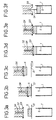
- the method of the invention as described above is advantageously used for the packaging and storage of compacted nuclear waste. It is described in more detail in this context nuclear, with reference to Figures 3a to 3f attached.
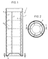
- Figures 1 and 2 show a container of the invention.
- Figure 1 is a longitudinal section along I-I of Figure 2; said figure 2 is a section according to II - II of said figure 1. Said container is shown "filled”.
- FIGS. 3a to 3f illustrate an implementation of the method of filling of a container of the invention (block diagram).
- FIGs 1 and 2 there is shown in 1 a container of the invention. he it is a cylindrical container with circular section. In a way characteristic, it is equipped in its interior volume with five flat springs corrugated 2. Said springs 2 are joined at 3, by welding, to said container 1. They are connected together, at the bottom of said container 1, by a torus 4, left free. They develop their undulations, along their length, along the axial wall 1 ' of said container 1. The products stored within said container are shown diagrammatically at 5 container 1.
- Said container 1 is intended to be filled with compacted waste radioactive 5 or pancakes 5.
- Said container 1 is of the type shown in the Figures 1 and 2.
- Said waste 5, coming from the press, is placed beforehand on a cylindrical turntable 21 having a notch (passage).
- Container 1 of type CHA is placed below said plate 21. It rests on the jack of a lift transfer cart (not shown) (Fig. 3a).
- the gripping head 22 At the start of a cycle for introducing compacted waste 5 into the container 1, the gripping head 22 is in the high position and the turntable 21 positions said compacted waste 5 by rotation, placing it in the axis of said gripping head 22 ( Figure 3a).
- Said gripping head 22 then descends by the "N • 1 translation” system until contact with its probe assembly with the compacted waste 5, which identifies the presence of said waste 5.
- the association of the sensor with a synchro-resolver allows to measure the height h ′ of the waste 5.
- the three elastic jaws of the clamping device 23 then ensure that the waste 5 is gripped over a certain height (FIG. 3b).
- the gripping head 22 rises by the "N • 1 translation” system.
- the turntable 21 rotates to present its passage notch under said head 22, thus leaving free access to the container 1 which is located below said turntable 21 and in the axis of the head 22 (FIG. 3c) .
- the gripping head 22 provided with the compacted waste 5 then descends by the "translation N • 1" system to a predefined height and partially introduces said compacted waste 5 into the container 1, along its longitudinal axis ( Figure 3d).
- the gripping bracket measures the space still available in said container 1 using the probe assembly and of the push cylinder 24, within the limit of the latter's travel.
- a CHA container has a ferrule at the top (the diameter inside of the ferrule flange is 400 mm) and a useful height of about 1 m. It is used to store compacted nuclear waste (wafers resulting from compacting of shells and tips in a case).
- Said container is equipped with locking means according to the invention.
- the said means have the function of blocking waste compacted during the filling phase, when no thrust is exerted on the last waste introduced, as well as during the phases of handling and transport of CHA. Said means also protect, during these two phases of use of the container, its inner envelope.
- Said locking means consist of five wavy flat springs maintained in a vertical position along the inner wall of the CHA. They are evenly distributed along the shell, every 72 ° (the waste stored are thus perfectly centered). Each of said springs is fixed in the upper part of the CHA by welding on the ferrule. The five springs are connected by a free torus in lower part of the CHA.
- This container can in particular be filled according to the second variant of the method of the invention, specified above and explained with reference to FIGS. 3a to 3f.
- h ' greater than h' minimum
- h ' minimum D 2 -d 2 ; D representing the internal diameter of the CHA and d the diameter of the waste).
Landscapes
- Engineering & Computer Science (AREA)
- Mechanical Engineering (AREA)
- Physics & Mathematics (AREA)
- General Engineering & Computer Science (AREA)
- High Energy & Nuclear Physics (AREA)
- Processing Of Solid Wastes (AREA)
- Basic Packing Technique (AREA)
- Refuse Receptacles (AREA)
Description
- de limiter voire empêcher tout endommagement de l'enveloppe intérieure (paroi(s), fond) du CHA pendant son remplissage ainsi que pendant les phases de manutention et de transport dudit CHA;
- d'assurer un positionnement géométrique stable des déchets compactés au sein du CHA, tout en perdant un minimum de volume dans ledit CHA.
- permettre l'introduction, dans le CHA, des déchets compactés, l'un après l'autre, dans le sens de leur hauteur; lesdits déchets, vu leur nature, étant manipulés à distance, en cellule;
- empêcher leur chute gravitaire au sein dudit CHA;
- assurer leur empilement, dans le sens de leur hauteur;
- limiter leur mouvement, dans le CHA, une fois qu'ils y sont mis en place.
- la manipulation desdits produits grâce à des moyens de manutention;
- leur introduction et positionnement par appui forcé (en force), au sein dudit conteneur, grâce auxdits moyens de manutention, coopérant si nécessaire avec des moyens complémentaires; la force développée étant suffisante pour vaincre les forces de frottement exercées par les moyens de blocage.
- un châssis principal comportant des galets de guidage permettant une première translation verticale appelée "translation N•1" (figures 3b à 3e);
- un dispositif de serrage à trois mors élastiques 23, des déchets compactés 5, à déplacement concentrique par came;
- un vérin pousseur 24 permettant une poussée verticale sur les déchets compactés 5 introduits partiellement dans le conteneur 1 et intégrant un limiteur d'effort élastique avec capteur. Ladite poussée verticale ou seconde translation verticale est appelée "translation N•2" (figure 3f);
- un ensemble de palpeurs de déchets compactés 5 (ou galettes) avec capteur.
- Géométrie :
- Longueur à vide = légèrement inférieure à la hauteur utile du conteneur;
- Largeur = 20 mm;
- Epaisseur = 2 mm;
- Matériau
- Acier inoxydable (en raison de la nature des déchets): Z 12 CN 18-10;
- Ce paramètre est dimensionnant vis à vis des caractéristiques mécaniques des ressorts;
- Ondulations :
- Les ondulations sont disposées dans la longueur du ressort;
- Nombre d'ondes = 13;
- Pas d'une onde à vide = 78,5 mm
- Amplitude d'une onde à vide = 21 mm;
- Effort normal par onde pour une amplitude de 15,5 mm = 80 daN;
Claims (10)
- Conteneur (1) de conditionnement et de stockage, de forme cylindrique ou prismatique, d'une hauteur h, ouvert ou susceptible de s'ouvrir pour son remplissage à son extrémité axiale supérieure; particulièrement adapté au conditionnement et au stockage confinés de déchets dangereux, manipulés à distance; caractérisé en ce qu'il est équipé, dans son volume intérieur, le long de sa (ses) paroi(s) axiale(s) (1'), sur sensiblement toute sa hauteur h, de moyens de blocage (2), capables de se déformer radialement de manière élastique par contact direct avec les produits (5) introduits en son sein; lesdits moyens de blocage (2) ne permettant l'introduction et le mouvement desdits produits (5) au sein dudit conteneur (1) que par appui forcé sur lesdits produits (5).
- Conteneur (1) selon la revendication 1, caractérisé en ce que lesdits moyens de blocage (2) sont répartis, de manière régulière, sur la face interne de sa (ses) paroi(s) axiale(s) (1').
- Conteneur (1) selon l'une des revendications 1 ou 2, caractérisé en ce que lesdits moyens de blocage (2) consistent en des éléments de ressorts ou en des ressorts plats ondulés dont les ondulations se développent suivant leur longueur et qui sont maintenus en position sensiblement verticale le long de la (des) paroi(s) axiale(s) (1') dudit conteneur (1).
- Conteneur (1) selon la revendication 3, caractérisé en ce que lesdits moyens de blocage (2) consistent en au moins deux, avantageusement au moins trois ressorts plats ondulés dont la longueur correspond à la hauteur de remplissage dudit conteneur (1).
- Conteneur (1) selon la revendication 4, caractérisé en ce que lesdits ressorts plats ondulés sont fixés en partie haute dudit conteneur (1).
- Conteneur (1) selon l'une des revendications 4 ou 5, caractérisé en ce que lesdits ressorts plats ondulés sont reliés entre eux, en partie basse dudit conteneur (1), par un tore (4) libre.
- Procédé de remplissage d'un conteneur (1) selon l'une quelconque des revendications 1 à 6 avec des produits (5) présentant une forme cylindrique ou prismatique coïncidant avec celle du conteneur (1) et une hauteur h', inférieure ou égale à la hauteur h dudit conteneur (1), caractérisé en ce qu'il comprend :la manipulation desdits produits (5) grâce à des moyens de manutention (23),leur introduction et positionnement, par appui forcé au sein dudit conteneur (1), grâce auxdits moyens de manutention (23) coopérant si nécessaire avec des moyens complémentaires (24); la force développée étant suffisante pour vaincre les forces de frottement exercées par les moyens de blocage (2).
- Procédé selon la revendication 7, caractérisé en ce que lesdits produits (5) sont manipulés grâce à des moyens de manutention tels des ventouses ou électroaimants qui peuvent être introduits au sein du conteneur (1); le premier desdits produits (5) étant positionné directement en partie basse dudit conteneur (1), l'(les) éventuel(s) suivant(s) étant ensuite positionné(s) successivement de la même façon.
- Procédé selon la revendication 7, caractérisé en ce que lesdits produits (5) sont manipulés grâce à des moyens de manutention (23) tels des ventouses, électroaimants ou pinces et positionnés en plusieurs temps; chacun d'entre eux étant tout d'abord introduit partiellement dans le conteneur (1) grâce auxdits moyens de manutention (23) puis désolidarisé desdits moyens (23) et soumis à l'action d'un vérin pousseur (24) pour son introduction complète dans ledit conteneur (1); ledit vérin (24) poussant chacun desdits produits (5) jusqu'à sa position finale dans ledit conteneur (1) ou ne poussant chacun desdits produits (5) ainsi que, le cas échéant, celui (ceux) introduit(s) avant lui, que sur une faible course, suffisante à dégager l'entrée dudit conteneur (1).
- Mise en oeuvre du procédé selon l'une quelconque des revendications 7 à 9, pour le conditionnement et le stockage de déchets nucléaires compactés.
Applications Claiming Priority (2)
| Application Number | Priority Date | Filing Date | Title |
|---|---|---|---|
| FR9513517A FR2741049B1 (fr) | 1995-11-15 | 1995-11-15 | Conteneurs de conditionnement et de stockage, notamment de dechets dangereux manipules a distance ; procede pour leur remplissage |
| FR9513517 | 1995-11-15 |
Publications (2)
| Publication Number | Publication Date |
|---|---|
| EP0774761A1 EP0774761A1 (fr) | 1997-05-21 |
| EP0774761B1 true EP0774761B1 (fr) | 1999-05-12 |
Family
ID=9484581
Family Applications (1)
| Application Number | Title | Priority Date | Filing Date |
|---|---|---|---|
| EP96402437A Expired - Lifetime EP0774761B1 (fr) | 1995-11-15 | 1996-11-14 | Conteneur de conditionnement et de stockage, notamment de déchets dangereux manipulés à distance; procédé pour leur remplissage et mise en oeuvre de ce procédé pour le conditionnement et le stockage de déchets nucléaires compactés |
Country Status (6)
| Country | Link |
|---|---|
| US (1) | US5733088A (fr) |
| EP (1) | EP0774761B1 (fr) |
| JP (1) | JP3980686B2 (fr) |
| DE (1) | DE69602413T2 (fr) |
| FR (1) | FR2741049B1 (fr) |
| RU (1) | RU2145450C1 (fr) |
Families Citing this family (10)
| Publication number | Priority date | Publication date | Assignee | Title |
|---|---|---|---|---|
| ATE223836T1 (de) * | 1999-08-23 | 2002-09-15 | Sig Pack Systems Ag | Vorrichtung zum zuführen von produktegruppen, insbesondere biskuits, in verpackungsbehälter |
| RU2164044C1 (ru) * | 2000-04-17 | 2001-03-10 | Волков Михаил Александрович | Способ упаковки радиоактивных отходов в защитный контейнер и корпус контейнера для его осуществления |
| US6741669B2 (en) * | 2001-10-25 | 2004-05-25 | Kenneth O. Lindquist | Neutron absorber systems and method for absorbing neutrons |
| FR2848887B1 (fr) | 2002-12-20 | 2006-01-20 | Cie Generale Des Matieres Nucleaires | Elaboration d'un conteneur ferme, ledit conteneur ferme et ses elements constitutifs |
| NL1033209C2 (nl) * | 2006-01-12 | 2007-12-04 | Food Processing Systems | Inrichting voor het vullen van dozen of kratten. |
| FR2907961B1 (fr) * | 2006-10-26 | 2009-01-23 | Cogema | Conteneur pour le stockage de dechets radioactifs. |
| RU2622772C1 (ru) * | 2016-04-27 | 2017-06-20 | Акционерное Общество "Российский Концерн По Производству Электрической И Тепловой Энергии На Атомных Станциях" (Ао "Концерн Росэнергоатом") | Пенал для хранения несущих труб и/или штанг тепловыделяющих сборок отработавшего ядерного топлива |
| RU171409U1 (ru) * | 2016-12-16 | 2017-05-30 | Федеральное государственное бюджетное образовательное учреждение высшего образования "Пермский государственный медицинский университет имени академика Е.А. Вагнера" Министерства здравоохранения Российской Федерации | Сепаратор для хранения биопрепаратов зубов с целью моделирования искусственного кариеса |
| CN114203321B (zh) * | 2021-11-11 | 2024-05-03 | 淄博鑫旭电源科技有限公司 | 一种核废料料桶顶升震动灌装装置及其灌装方法 |
| CN116153548B (zh) * | 2022-12-30 | 2024-03-26 | 江苏佳核新能源科技有限公司 | 一种中低水平放射性废物用高完整性容器及其制作模具 |
Family Cites Families (24)
| Publication number | Priority date | Publication date | Assignee | Title |
|---|---|---|---|---|
| US843325A (en) * | 1906-02-09 | 1907-02-05 | Arthur L Canfield | Method of packing isinglass. |
| US939021A (en) * | 1909-04-01 | 1909-11-02 | John D Hendrix | Liquid-cooler. |
| US2695126A (en) * | 1953-10-14 | 1954-11-23 | Russell Corp | Ice-cream sandwich package |
| US3405744A (en) * | 1967-02-08 | 1968-10-15 | Benjamin P. Bowman | Method and apparatus for packing material into containers |
| JPS4918073B1 (fr) * | 1970-01-16 | 1974-05-07 | ||
| US3650120A (en) * | 1970-04-20 | 1972-03-21 | Richard D Harza | Method for disposing of garbage and refuse |
| US3778965A (en) * | 1971-12-17 | 1973-12-18 | Standard Packaging Corp | Loading system for packing machine |
| US3842573A (en) * | 1973-01-29 | 1974-10-22 | Currency Syst Inc | Method and apparatus for packaging coins |
| EP0044381B1 (fr) * | 1980-05-19 | 1985-04-03 | Asea Ab | Méthode pour traiter les matériaux radioactifs et récipient pour enfermer de tels matériaux |
| US4645624A (en) * | 1982-08-30 | 1987-02-24 | Australian Atomic Energy Commission | Containment and densification of particulate material |
| US4554868A (en) * | 1983-01-12 | 1985-11-26 | Zimmer John C | Apparatus for compacting refuse with stabilizers |
| SE442562B (sv) * | 1983-01-26 | 1986-01-13 | Asea Ab | Sett att innesluta radioaktivt eller annat farligt avfall och en behallare for sadant avfall |
| US4683110A (en) * | 1985-06-14 | 1987-07-28 | Proto-Power Corporation | Apparatus and method for consolidating spent fuel rods |
| EP0211528B1 (fr) * | 1985-07-16 | 1991-10-23 | Australian Nuclear Science And Technology Organisation | Appareil à transfert et stabilisateur de chaleur |
| JPS6217699A (ja) * | 1985-07-17 | 1987-01-26 | 株式会社日立製作所 | 高放射性固体廃棄物減容片の収納容器 |
| US4800703A (en) * | 1986-08-06 | 1989-01-31 | Prototype Equipment Corp. | Horizontal pouch packer |
| US4822555A (en) * | 1987-06-18 | 1989-04-18 | Nuclear Services Company | Container for plate-like objects |
| US4760784A (en) * | 1987-07-15 | 1988-08-02 | Tennessee Valley Authority | Compacting plate locking device used for packaging expansible material |
| FR2631151B1 (fr) * | 1988-05-03 | 1991-02-15 | Commissariat Energie Atomique | Chemise pour dechets a compacter et conteneur pour cette chemise |
| FR2633088B1 (fr) * | 1988-06-15 | 1990-11-16 | Sgn Soc Gen Tech Nouvelle | Dispositif pour cisailler un assemblage de tubes |
| JPH0631874B2 (ja) * | 1988-09-02 | 1994-04-27 | 動力炉・核燃料開発事業団 | 被圧縮物を容器内に圧縮収納する方法 |
| FR2700295B1 (fr) * | 1993-01-14 | 1995-03-31 | Sgn Soc Gen Tech Nouvelle | Compactage de déchets métalliques susceptibles de s'enflammer et/ou d'exploser. |
| FR2700494B1 (fr) * | 1993-01-15 | 1995-04-07 | Sgn Soc Gen Tech Nouvelle | Procédé et dispositif de compactage, particulièrement adaptés au compactage de matières dangereuses et notamment de déchets radioactifs. |
| US5391887A (en) * | 1993-02-10 | 1995-02-21 | Trustees Of Princeton University | Method and apparatus for the management of hazardous waste material |
-
1995
- 1995-11-15 FR FR9513517A patent/FR2741049B1/fr not_active Expired - Fee Related
-
1996
- 1996-10-31 US US08/741,939 patent/US5733088A/en not_active Expired - Lifetime
- 1996-11-14 DE DE69602413T patent/DE69602413T2/de not_active Expired - Lifetime
- 1996-11-14 EP EP96402437A patent/EP0774761B1/fr not_active Expired - Lifetime
- 1996-11-14 RU RU96121885A patent/RU2145450C1/ru not_active IP Right Cessation
- 1996-11-15 JP JP30516696A patent/JP3980686B2/ja not_active Expired - Lifetime
Also Published As
| Publication number | Publication date |
|---|---|
| FR2741049B1 (fr) | 1998-01-30 |
| US5733088A (en) | 1998-03-31 |
| JPH09178893A (ja) | 1997-07-11 |
| JP3980686B2 (ja) | 2007-09-26 |
| DE69602413T2 (de) | 1999-10-28 |
| DE69602413D1 (de) | 1999-06-17 |
| EP0774761A1 (fr) | 1997-05-21 |
| RU2145450C1 (ru) | 2000-02-10 |
| FR2741049A1 (fr) | 1997-05-16 |
Similar Documents
| Publication | Publication Date | Title |
|---|---|---|
| EP0774761A1 (fr) | Conteneurs de conditionnement et de stockage, notamment de déchets dangereux manipulés à distance; procédé pour leur remplissage | |
| EP0871180B1 (fr) | Emballage de transport de colis dangereux, tels que des colis nucléaires de forte activité | |
| FR2918649A1 (fr) | Emballage de stockage longue duree a fond amovible. | |
| FR2964091A1 (fr) | Dispositif de manutention de futs, installation de transfert de materiau en poudre et procede de transfert | |
| EP0105002A1 (fr) | Procédé et dispositif pour le stockage par compactage de matériaux souples contaminés | |
| EP2406790B1 (fr) | Étui de stockage de combustible nucléaire usagé à fermeture facilitée | |
| EP0506511B1 (fr) | Dispositif de fixation d'un objet sur une structure de transport et en particulier dispositif de verrouillage d'un assemblage combustible dans un conteneur | |
| EP2287096B1 (fr) | Support basculant pour réservoir | |
| WO2009144256A1 (fr) | Conteneur de conditionnement de déchets nucléaires a couvercle emmanche a force | |
| EP1851131B1 (fr) | Unite de transport de panneaux | |
| EP0009424A1 (fr) | Dispositif et procédé de transfert et de conditionnement dans une gaine étanche de produits nocifs | |
| EP2794083A1 (fr) | Support de capteur pour un reacteur en cours de chargement | |
| FR2959986A1 (fr) | Palette pour supporter des futs de matieres radioactives | |
| WO2023118714A1 (fr) | Systeme amelioré de support d'emballage de transport de matières radioactives, configuré pour permettre son pivotement d'une position horizontale de transport à une position verticale d'exploitation | |
| FR2947248A1 (fr) | Palette | |
| FR2766062A1 (fr) | Unite de moulage de produits alimentaires, notamment pour la cuisson des jambons | |
| FR2502600A3 (fr) | Appareil destine a saisir des futs a contenu fortement radioactif ouverts ou fermes par un couvercle | |
| FR2741330A1 (fr) | Mecanisme de basculement de benne | |
| EP3504004B1 (fr) | Conteneur pour poche souple comprenant deux positions de fonctionnement | |
| FR2750119A1 (fr) | Dispositif de stockage et de manutention demontable | |
| FR2584854A1 (fr) | Procede et installation de compactage et de conditionnement de dechets solides radio-actifs de faible ou moyenne activite. | |
| EP0461017B1 (fr) | Procédé et dispositif de fabrication d'un fût et fût obtenu selon ce procédé | |
| EP0633215A1 (fr) | Système anti-chute mécanique pour un dispositif de préhension d'objets lourds | |
| FR2803341A1 (fr) | Dispositif d'ancrage sur containers | |
| FR2808787A1 (fr) | Procede de transfert de charge par basculement et dispositif mettant en oeuvre le procede |
Legal Events
| Date | Code | Title | Description |
|---|---|---|---|
| PUAI | Public reference made under article 153(3) epc to a published international application that has entered the european phase |
Free format text: ORIGINAL CODE: 0009012 |
|
| AK | Designated contracting states |
Kind code of ref document: A1 Designated state(s): BE CH DE ES FR GB IT LI NL |
|
| 17P | Request for examination filed |
Effective date: 19970716 |
|
| GRAG | Despatch of communication of intention to grant |
Free format text: ORIGINAL CODE: EPIDOS AGRA |
|
| 17Q | First examination report despatched |
Effective date: 19980824 |
|
| GRAG | Despatch of communication of intention to grant |
Free format text: ORIGINAL CODE: EPIDOS AGRA |
|
| GRAH | Despatch of communication of intention to grant a patent |
Free format text: ORIGINAL CODE: EPIDOS IGRA |
|
| GRAH | Despatch of communication of intention to grant a patent |
Free format text: ORIGINAL CODE: EPIDOS IGRA |
|
| GRAA | (expected) grant |
Free format text: ORIGINAL CODE: 0009210 |
|
| AK | Designated contracting states |
Kind code of ref document: B1 Designated state(s): BE CH DE ES FR GB IT LI NL |
|
| PG25 | Lapsed in a contracting state [announced via postgrant information from national office to epo] |
Ref country code: IT Free format text: LAPSE BECAUSE OF FAILURE TO SUBMIT A TRANSLATION OF THE DESCRIPTION OR TO PAY THE FEE WITHIN THE PRE;WARNING: LAPSES OF ITALIAN PATENTS WITH EFFECTIVE DATE BEFORE 2007 MAY HAVE OCCURRED AT ANY TIME BEFORE 2007. THE CORRECT EFFECTIVE DATE MAY BE DIFFERENT FROM THE ONE RECORDED.SCRIBED TIME-LIMIT Effective date: 19990512 Ref country code: ES Free format text: THE PATENT HAS BEEN ANNULLED BY A DECISION OF A NATIONAL AUTHORITY Effective date: 19990512 |
|
| REG | Reference to a national code |
Ref country code: CH Ref legal event code: EP |
|
| REF | Corresponds to: |
Ref document number: 69602413 Country of ref document: DE Date of ref document: 19990617 |
|
| GBT | Gb: translation of ep patent filed (gb section 77(6)(a)/1977) |
Effective date: 19990616 |
|
| REG | Reference to a national code |
Ref country code: CH Ref legal event code: NV Representative=s name: BOVARD AG PATENTANWAELTE |
|
| PLBE | No opposition filed within time limit |
Free format text: ORIGINAL CODE: 0009261 |
|
| STAA | Information on the status of an ep patent application or granted ep patent |
Free format text: STATUS: NO OPPOSITION FILED WITHIN TIME LIMIT |
|
| 26N | No opposition filed | ||
| REG | Reference to a national code |
Ref country code: GB Ref legal event code: IF02 |
|
| REG | Reference to a national code |
Ref country code: CH Ref legal event code: PFA Owner name: COMPAGNIE GENERALE DES MATIERES NUCLEAIRES Free format text: COMPAGNIE GENERALE DES MATIERES NUCLEAIRES#2, RUE PAUL DAUTIER#78140 VELIZY VILLACOUBLAY (FR) -TRANSFER TO- COMPAGNIE GENERALE DES MATIERES NUCLEAIRES#2, RUE PAUL DAUTIER#78140 VELIZY VILLACOUBLAY (FR) |
|
| REG | Reference to a national code |
Ref country code: FR Ref legal event code: PLFP Year of fee payment: 20 |
|
| PGFP | Annual fee paid to national office [announced via postgrant information from national office to epo] |
Ref country code: FR Payment date: 20150924 Year of fee payment: 20 |
|
| PGFP | Annual fee paid to national office [announced via postgrant information from national office to epo] |
Ref country code: CH Payment date: 20151105 Year of fee payment: 20 Ref country code: DE Payment date: 20151109 Year of fee payment: 20 Ref country code: GB Payment date: 20151116 Year of fee payment: 20 |
|
| PGFP | Annual fee paid to national office [announced via postgrant information from national office to epo] |
Ref country code: BE Payment date: 20151123 Year of fee payment: 20 Ref country code: NL Payment date: 20151014 Year of fee payment: 20 |
|
| REG | Reference to a national code |
Ref country code: DE Ref legal event code: R071 Ref document number: 69602413 Country of ref document: DE |
|
| REG | Reference to a national code |
Ref country code: NL Ref legal event code: MK Effective date: 20161113 |
|
| REG | Reference to a national code |
Ref country code: CH Ref legal event code: PL |
|
| REG | Reference to a national code |
Ref country code: GB Ref legal event code: PE20 Expiry date: 20161113 |
|
| PG25 | Lapsed in a contracting state [announced via postgrant information from national office to epo] |
Ref country code: GB Free format text: LAPSE BECAUSE OF EXPIRATION OF PROTECTION Effective date: 20161113 |