EP0774623A1 - Burner with segmented burner deck - Google Patents
Burner with segmented burner deck Download PDFInfo
- Publication number
- EP0774623A1 EP0774623A1 EP96203215A EP96203215A EP0774623A1 EP 0774623 A1 EP0774623 A1 EP 0774623A1 EP 96203215 A EP96203215 A EP 96203215A EP 96203215 A EP96203215 A EP 96203215A EP 0774623 A1 EP0774623 A1 EP 0774623A1
- Authority
- EP
- European Patent Office
- Prior art keywords
- burner
- burner deck
- deck
- parts
- housing
- Prior art date
- Legal status (The legal status is an assumption and is not a legal conclusion. Google has not performed a legal analysis and makes no representation as to the accuracy of the status listed.)
- Withdrawn
Links
Images


Classifications
-
- F—MECHANICAL ENGINEERING; LIGHTING; HEATING; WEAPONS; BLASTING
- F23—COMBUSTION APPARATUS; COMBUSTION PROCESSES
- F23D—BURNERS
- F23D14/00—Burners for combustion of a gas, e.g. of a gas stored under pressure as a liquid
- F23D14/46—Details, e.g. noise reduction means
- F23D14/48—Nozzles
- F23D14/58—Nozzles characterised by the shape or arrangement of the outlet or outlets from the nozzle, e.g. of annular configuration
-
- F—MECHANICAL ENGINEERING; LIGHTING; HEATING; WEAPONS; BLASTING
- F23—COMBUSTION APPARATUS; COMBUSTION PROCESSES
- F23D—BURNERS
- F23D14/00—Burners for combustion of a gas, e.g. of a gas stored under pressure as a liquid
- F23D14/02—Premix gas burners, i.e. in which gaseous fuel is mixed with combustion air upstream of the combustion zone
-
- F—MECHANICAL ENGINEERING; LIGHTING; HEATING; WEAPONS; BLASTING
- F23—COMBUSTION APPARATUS; COMBUSTION PROCESSES
- F23D—BURNERS
- F23D2211/00—Thermal dilatation prevention or compensation
Definitions
- the invention relates to a burner for use in a gas-fired burner device, according to the preamble of claim 1. Such a burner is known from practice.
- the known burner comprises a box-shaped housing which is closed at the top by a curved burner deck.
- the burner deck consists of a plate member which is provided over the entire surface thereof with outflow openings through which during use gas or a gas/air mixture can flow from the inside of the housing to the environment and can burn on top of the burner deck.
- Provided along the entire upper circumferential edge of the housing is an inwardly open groove in which the circumferential edge of the burner deck is confined with a proper fit, so as to allow movement within the groove approximately in the plane of the burner deck. This is of great importance since the burner deck will be strongly heated during use and should then be able to deform freely, in particular expand.
- the burner deck of this known burner is made from a relatively thick plate member of a high-grade metal. As a consequence, the burner deck is relatively expensive. Further, the maximum allowable surface area of the burner deck is limited. Moreover, it is found that the deformations of the burner deck during use, in particular upon prolonged use, are such that the burner deck is partly released from the groove, loses its shape permanently or even breaks or tears, for instance as a consequence of thermal cracks, in particular if the burner is used as a so-called modulating gas burner and in burners with a non-planar burner deck. This has as a consequence that this known burner, or at least the burner deck, has a relatively short life and is costly in manufacture and use. Moreover, giving the burner deck a shape other than a substantially flat shape is not easy to realize. This can be disadvantageous in some cases because a flat burner deck can lead to an undesired flame pattern and relatively much noise.
- the object of the invention is to provide a burner of the type described in the preamble, whereby the disadvantages mentioned are avoided, while the advantages thereof are maintained.
- a burner according to the invention is characterized by the features according to claim 1.
- the burner deck parts By dividing the burner deck into different burner deck parts, which are movably supported on all sides by at least the housing and a bridge, a stabler burner deck allowing more flexible arrangement and shaping is obtained, which moreover can be manufactured more cheaply.
- the burner deck parts can be manufactured from cheaper, less high-grade and/or less voluminous material than a burner deck of comparable dimensions. Moreover, the deformations of the burner deck parts, given equal conditions of use, are smaller and can at the least be accommodated better in the supporting construction.
- a further advantage of different burner deck parts is that they can be separately exchangeable and replaceable, so that in case of damage it is not necessary to replace the entire burner deck.
- burner deck parts it is easier to manufacture asymmetrical burner decks, which are individually adaptable to the type of burner device in which the burner is to be used, so that burners can be composed for different burner devices using comparable or identical parts.
- the burner deck parts and intermediate bridges moreover make greater burner deck surfaces (length and/or width) possible, given equal material conditions, so that relatively large burners can be manufactured, supplied from one housing and with relatively thin-walled inexpensive burner decks.
- the slight thickness provides the advantage that material stresses resulting from varying heat loads have less influence on the burner deck, so that the quality and the life are appreciably increased over known burners. This advantage can be further enhanced through a suitable choice of material.
- a burner according to the invention is characterized by the features according to claim 2 and/or 3.
- Such a burner provides the advantage that the or each bridge increases the stiffness of the housing and at the same time divides the burner deck into at least two burner deck parts.
- the housing too can be shaped relatively simply.
- a non-planar burner deck can be manufactured using relatively flat burner deck parts.
- this provides the advantage that thereby a favorable burner pattern can be obtained for a particular burner device without requiring that the burner deck parts be deformed, for instance bent.
- materials that can hardly be deformed, if at all can also be used for non-planar burner decks, such as curved or angled burner decks.
- a burner deck according to the invention is characterized by the features according to claim 4.
- the burner deck comprises at least four burner deck parts, two side by side and two behind each other.
- a relatively large burner deck can be formed, allowing the burner deck parts to have only relatively little stiffness, while they moreover undergo large deformations relative to the surface area.
- such an embodiment is particularly suitable for use with modulating burners and for highly varying heat loads.
- a burner according to the invention is characterized by the features according to claim 5.
- the burner has a burner deck constituting a superficies or shell, so that the burner is suitable in, for instance, a burner device with a cylindrical burner space.
- the use of the burner deck parts here offers the additional advantage that the shell-shaped burner deck is simple to build up.
- a burner according to the invention is characterized by the features according to claim 6.
- a pressure distributing plate under the burner deck has the advantage that, as a result, the gas or gas/air mixture flowing from the housing to the outflow openings in the burner deck does not reach the outflow openings directly but is diverted at least in the direction of flow. Moreover, due to the pressure distributing plate, the velocity of the gas or gas mixture is adjusted, in such a manner that optimum burner conditions are thereby obtained.
- the pressure distributing plate is preferably provided with spacing means, such as recessed or deepened portions, whereby the pressure distributing plate is held at a fixed distance from the burner deck. For that matter, this distance need not be the same throughout. The most suitable configuration is dependent inter alia on the burner device in which the burner is to be used.
- a burner according to the invention is characterized in an advantageous embodiment by the features according to claim 7.
- the flow velocity and the amount of the gas or gas mixture are adjusted locally so as to be different at the different positions.
- the gas will in each case be supplied to an outflow opening in a burner deck part at a different velocity and yield a different burning. Because the different burner deck parts are separated by bridges of a particular width, this effect is enhanced in an advantageous manner. For that matter, the same effect can be obtained or enhanced by providing throughflow openings with different surface areas.
- such a burner deck according to the invention is characterized by the features according to claim 9.
- Clustering the throughflow openings and/or the outflow openings can provide the advantage, in a burner according to the invention, that an irregular or at least non-uniform distribution within the flame pattern of the burner during use is obtained or enhanced.
- a number of burner deck parts are manufactured from perforated metal sheet. Such an embodiment can be produced relatively simply, accurately and cheaply and offers good conditions of use.
- At least a number of the burner deck parts are manufactured from ceramic material. Owing to the burner deck parts being relatively small, such burner deck parts can be manufactured relatively simply and they are less fragile, and they can moreover be made of flat design, without the burner deck itself having to be flat as well. This is particularly advantageous from the point of view of manufacturing technique.
- a burner according to the invention is further characterized by the features according to claim 14.
- the burner deck parts do not all have the same dimensions and/or shapes, the flame pattern of such a burner during use, regarded as a function of the position on the burner deck, can be irregular.
- the different burner deck parts can be shaped and positioned in such a manner that in spite of a non-central supply of the gas or gas mixture, yet a substantially uniform distribution thereof under the burner deck can be obtained.
- the invention further relates to a burner device comprising at least one burner according to the invention.
- Fig. 1 shows in top plan view a burner 1, provided with a housing 2 and a burner deck 3.
- the housing 2 comprises, as appears in particular from Figs. 3 and 4, two vertical longitudinal walls 4 extending parallel to each other, and two end walls 5, likewise extending approximately vertically and parallel to each other, which interconnect the longitudinal walls 4 to each other at the ends thereof.
- the housing 2 is therefore substantially box-shaped and open towards the underside.
- the end walls 5 have a curved upper side.
- the longitudinal walls 4 and the end walls 5 are outwardly flanged at their underside, so as to form a circumferential flange 6 for securing the burner 1 in a burner device.
- first deck edge part 9 Extending inwardly from the top of the longitudinal walls 4 is an inclined first deck edge part 9, approximately parallel to a part of the upper side of the end walls 5. Extending inwardly from the top of the end walls 5 in approximately horizontal direction is a second deck edge part 10.
- the first and second deck edge parts 9 and 10 together form a circumferential deck edge 11. Adjacent the middle of the longitudinal walls 4 the first deck edge parts 9 are interconnected through a curved bridge 12 which has a bending radius approximately equal to the bending radius of the upper side of the end walls 5. Accordingly, the deck edge 11, together with the bridge 12, defines a surface forming a part of the circumferential surface of a cylinder. This surface is the burner deck 3, or at least similar in shape thereto.
- the burner deck 3 comprises two burner deck parts 7, each approximately rectangular and provided with rows and columns of outflow openings 8.
- the configuration of the burner deck parts 7 will be further discussed hereinafter.
- the inwardly facing free edges 13 of the deck edge 11 and the bridge 12 together describe one of the openings 14 in which a burner deck part 7 is received.
- These free edges are designed as, or at least provided with, sliding guidance wings 15, in which the free edges 30 of the burner deck parts 7 are movably confined with a proper fit.
- the burner deck parts 7 can freely expand, shrink and move in their own plane but cannot move in any other direction. This is of importance in particular during the heating and cooling of the burner deck parts 7 and the housing 2 during use. As a result, stresses, damage and deformations in the burner deck parts 7 are prevented, so that their life and reliability are increased. This is of great importance, in particular for modulating burners, in view of the varying mechanical and thermal loads of the parts.
- a large burner deck 3 in a one-piece design has a disadvantage in that the deformations that may occur are relatively large as well, and hence are difficult to accommodate. Owing to the burner deck in a burner according to the invention being subdivided into smaller burner deck parts, which are supported on all sides in the sliding guidance wings 15, deformations can more simply be accommodated. As a result, the burner deck parts 3 can be manufactured more cheaply and/or better and/or from other, better materials.
- thinner plate material can be used than with the known burner, less stiff or less bearing material can be used, or material having a higher coefficient of expansion.
- different burner deck parts can be combined. This will be reverted to in the discussion of the configuration of the burner deck parts.
- the burner 1 is provided with a number of pressure distributing plates 16.
- Figs. 1-4 two such plates 16 are arranged one above the other, under the burner deck 3.
- Fig. 2 shows these two plates 16 within the burner 1 in bottom plan view.
- the two pressure distributing plates 16 substantially have a curved shape which corresponds approximately with the shape of the plane of the burner deck 3.
- the lower pressure distributing plate 16'' that is, the plate located farthest from the burner deck 3, is provided at the longitudinal edges thereof with a downwardly flanged edge 17 through which the plate 16'' has been secured against the inside of the longitudinal walls 4 and end walls 5 in sealing engagement therewith.
- a multiplicity of evenly distributed throughflow openings 18 have been provided in a central area. These throughflow openings 18 all have one preferred embodiment and all have the same throughflow area.
- Non-uniform should herein be understood to mean different in, for instance, mutual distance and/or size and/or shape and/or direction of throughflow, the arrangement being such that the flow pattern of the gas or gas/air mixture on the side of the upper pressure distributing plates 16' proximal to the burner deck 3 is not the same everywhere as the gas flows through the second throughflow openings 20.
- the lower pressure distributing plate 16'' is provided with a number of spacers 21 extending above the plane of the pressure distributing plate 16'' and abutting against the underside of the deepened portion 19 of the upper pressure distributing plates 16'.
- the upper pressure distributing plates 16'' are likewise provided with spacers 21, which abut against the underside of the burner deck parts 7.
- the outflow openings 8 in the burner deck parts 7 are grouped in clusters 22, which clusters 22 are separated from each other by intermediate edges 23.
- the clusters comprise twenty-four outflow openings 8 arranged in a regular pattern.
- each burner deck part 7 is reinforced and moreover an outflow opening pattern non-uniformly distributed over the burner deck is obtained.
- a non-uniform flame pattern can be obtained and/or enhanced in a burner according to the invention, inter alia through the above-described features such as pressure distributing plates, non-uniform distribution of throughflow openings and outflow openings and a burner deck divided into burner deck parts, while the burner deck parts can be different.
- the outflow openings 8 can be provided over the entire surface of the burner deck parts 7 or only over a part thereof, for instance a central area selected such that the edges 30 which are received in the sliding guidance wings 15 are massive or at least free of outflow openings.
- a burner according to the invention functions as follows.
- a combustible gas or preferably a gas/air mixture is supplied to the housing from, for instance, a blowing device which functions as a pre-mix device.
- the gas/air mixture is supplied in modulating manner and is forced through the first throughflow openings 18 in the lower pressure distributing plate 16'', distributed between the two pressure distributing plates 16 and diverted in the direction of flow, in the direction of the second throughflow openings 20 in the upper pressure distributing plates 16'.
- the pressure distributing plate or plates in a burner according to the invention provide, among other things, for a mixing and distribution of the gas or gas/air mixture, and/or for the creation of pressure differences therein.
- the irregularly supplied gas/air mixture is again adjusted in flow direction and flow velocity and thereafter forced through the outflow openings 8, where it is burnt above the burner deck parts 7.
- the burner deck parts 7 are thereby heated strongly, optionally to the point of being red hot, so that the burner deck parts 7 expand in a direction parallel to their own plane. Since the burner deck parts 7 can move in the sliding guidance wings 15 and expand relatively little with respect to the dimensions of the burner deck 3 as a result of their small dimensions, such expansion can readily be taken up. Accordingly, upon subsequent cooling, the burner deck can readily assume its original shape again. Owing to the confinement of the burner deck parts on all sides, the burner deck parts can be made of relatively little stiff design without this adversely affecting the action, the quality or the life of the burner.
- the relatively slight stiffness of the burner deck parts actually contributes to a long life of the burner.
- a limitation of the length of the burner deck parts 7 entails a marked improvement of the life of the burner, since the greatest problems due to expansion will occur in the longitudinal direction.
- the burner deck parts 7 can be formed, for instance, from perforated metal sheet, or from ceramic or mesh material.
- the burner deck parts can be manufactured from known superalloys which exhibit a high tensile strength and slight expansion at high temperatures, but precisely with burner deck parts according to the invention is it advantageous to use cheaper alloys such as iron-chromium-aluminum alloys or still cheaper alloys such as chromium-steel alloys, which are particularly suitable for gauze-shaped burner deck parts.
- Figs. 5A-5E show in top plan view and in sectional side elevation a series of burner deck arrangements which are possible while using features according to the invention.
- Fig. 5A shows a burner deck with a curved top surface, which consists of four rectangular burner deck parts 7A, while in addition to a bridge 12 between the sidewalls 4 a bridge 12' between the end walls 5 is included.
- the outflow openings 8 are slotted.
- Fig. 5B shows a comparable burner deck, which, however, is provided with two bridges 12 between the longitudinal walls 4 and one bridge 12' between the end walls 5, so that six burner deck parts 7B are obtained, which do not all have the same dimensions.
- the top surface of the burner deck is not curved but angled, while the burner deck parts 7B are flat.
- the outflow openings 8 are alternately slotted and circular.
- Fig. 5C shows an embodiment where the burner deck is divided in two burner deck parts 7C, which have a trapezoidal shape in that the bridge 12 has been arranged obliquely relative to the longitudinal direction of the burner, between the longitudinal walls 4.
- Fig. 5D shows an embodiment of a burner according to the invention where the housing is approximately circular and the burner deck 3 has a doubly curved surface.
- the burner deck 3 is divided by three bridges 12 into six identically shaped, triangular flat burner deck parts.
- a circular housing has as an advantage that the burner deck is large with respect to the circumferential wall of the housing, compared with a rectangular burner having a comparable burner deck surface. This means that less material is needed for such a burner housing.
- the triangular burner deck parts can also be curved in one or in two directions.
- Fig. 5E shows in partial cross section a cylindrical burner where the burner deck 3 substantially constitutes the superficies or shell of the burner.
- Four bridges 12 extend parallel to the longitudinal direction of the burner in, or at least parallel to, the superficies.
- the burner deck parts 7E are disposed between the bridges 12, likewise in the superficies, and in the embodiment shown are curved in one direction.
- two concentrically arranged pressure distributing plates 16' and 16'' are included within the burner, which in function and design further correspond substantially with the earlier described pressure distributing plates 16.
- the height of the inner pressure distributing plate 16'' is slightly less than the height of the outer pressure distributing plate 16', which has a height approximately corresponding with the height of the burner deck parts 7E.
- the burner deck parts 7 in the embodiments shown in Figs. 5A-5E naturally have their edges retained in sliding wings.
- This burner is closed at the top by a cover 24 whose edges have been flanged over the outside of the superficies and secured thereto.
- a supply opening 25 is formed by a neck part 26 extending downwards in the shape of a tube, which adjacent the free end thereof is provided with an annular securing flange 6.
- gas or a gas/air mixture can be supplied during use.
- a distributing cone may be further included.
- the burner deck parts 7E it is possible, in the case of a shell-shaped burner deck 3, for the burner deck parts 7E to be of entirely flat design, so that an at least partly facetted burner deck is obtained, while also burner deck parts can be arranged above each other.
- the top of such a burner can also be provided with one or more burner deck parts and the burner can have the shape of a segment of a sphere or ellipsoid.
- the burner deck can have a different outer shape, for instance curved or polygonal.
- other burner deck arrangements can be used than those shown by way of example only.
- a different number can be chosen; other pressure distributing means can be used or they can be omitted.
- the throughflow openings and/or the outflow openings can be differently grouped, positioned and/or shaped.
- the outflow openings or the throughflow openings can be provided with diverting means for changing the direction of the gas/air mixture flow.
- they can be made, for instance, of venturi-shaped design.
- the burner deck can be provided with closed parts, for instance a closed top surface over the length of the burner, with a number of burner deck parts on opposite sides, and moreover can be made, for instance, of flat or concave design.
- the housing can of course be adapted to the desired application as to material use and design in a variety of ways.
Landscapes
- Engineering & Computer Science (AREA)
- Chemical & Material Sciences (AREA)
- Combustion & Propulsion (AREA)
- Mechanical Engineering (AREA)
- General Engineering & Computer Science (AREA)
- Gas Burners (AREA)
Abstract
A burner (1) for use in a gas-fired burner device, comprising a housing (2) at least partly covered by a burner deck (3) provided with outflow openings (8) for allowing, during use, the passage of a gas or gas/air mixture from the inside of the housing to the environment, with the circumferential edges of the burner deck being retained so as to be movable relative to the housing, wherein the burner deck comprises a series of burner deck parts (7) arranged next to each other, which burner deck parts each comprise a row of outflow openings in communication with the inside of the housing, while between burner deck parts arranged next to each other bridges (12) are included which are fixedly connected with the housing, in which bridges the proximal edges (30) of the burner deck parts connecting thereto are movably retained, the arrangement being such that during use each burner deck part can deform at least in the plane of the burner deck part in question, independently of the other burner deck parts the housing and the bridges.
Description
- The invention relates to a burner for use in a gas-fired burner device, according to the preamble of
claim 1. Such a burner is known from practice. - The known burner comprises a box-shaped housing which is closed at the top by a curved burner deck. The burner deck consists of a plate member which is provided over the entire surface thereof with outflow openings through which during use gas or a gas/air mixture can flow from the inside of the housing to the environment and can burn on top of the burner deck. Provided along the entire upper circumferential edge of the housing is an inwardly open groove in which the circumferential edge of the burner deck is confined with a proper fit, so as to allow movement within the groove approximately in the plane of the burner deck. This is of great importance since the burner deck will be strongly heated during use and should then be able to deform freely, in particular expand.
- The burner deck of this known burner is made from a relatively thick plate member of a high-grade metal. As a consequence, the burner deck is relatively expensive. Further, the maximum allowable surface area of the burner deck is limited. Moreover, it is found that the deformations of the burner deck during use, in particular upon prolonged use, are such that the burner deck is partly released from the groove, loses its shape permanently or even breaks or tears, for instance as a consequence of thermal cracks, in particular if the burner is used as a so-called modulating gas burner and in burners with a non-planar burner deck. This has as a consequence that this known burner, or at least the burner deck, has a relatively short life and is costly in manufacture and use. Moreover, giving the burner deck a shape other than a substantially flat shape is not easy to realize. This can be disadvantageous in some cases because a flat burner deck can lead to an undesired flame pattern and relatively much noise.
- The object of the invention is to provide a burner of the type described in the preamble, whereby the disadvantages mentioned are avoided, while the advantages thereof are maintained. To that effect, a burner according to the invention is characterized by the features according to
claim 1. - By dividing the burner deck into different burner deck parts, which are movably supported on all sides by at least the housing and a bridge, a stabler burner deck allowing more flexible arrangement and shaping is obtained, which moreover can be manufactured more cheaply. The burner deck parts can be manufactured from cheaper, less high-grade and/or less voluminous material than a burner deck of comparable dimensions. Moreover, the deformations of the burner deck parts, given equal conditions of use, are smaller and can at the least be accommodated better in the supporting construction. A further advantage of different burner deck parts is that they can be separately exchangeable and replaceable, so that in case of damage it is not necessary to replace the entire burner deck. Further, with different burner deck parts it is easier to manufacture asymmetrical burner decks, which are individually adaptable to the type of burner device in which the burner is to be used, so that burners can be composed for different burner devices using comparable or identical parts. The burner deck parts and intermediate bridges moreover make greater burner deck surfaces (length and/or width) possible, given equal material conditions, so that relatively large burners can be manufactured, supplied from one housing and with relatively thin-walled inexpensive burner decks. In particular, the slight thickness provides the advantage that material stresses resulting from varying heat loads have less influence on the burner deck, so that the quality and the life are appreciably increased over known burners. This advantage can be further enhanced through a suitable choice of material.
- In an advantageous embodiment, a burner according to the invention is characterized by the features according to
claim 2 and/or 3. - Such a burner provides the advantage that the or each bridge increases the stiffness of the housing and at the same time divides the burner deck into at least two burner deck parts. As a result, the housing too can be shaped relatively simply. Owing to the burner deck being divided into at least two burner deck parts, a non-planar burner deck can be manufactured using relatively flat burner deck parts. For different types of burners, this provides the advantage that thereby a favorable burner pattern can be obtained for a particular burner device without requiring that the burner deck parts be deformed, for instance bent. As a consequence, materials that can hardly be deformed, if at all, can also be used for non-planar burner decks, such as curved or angled burner decks.
- In a preferred embodiment, a burner deck according to the invention is characterized by the features according to
claim 4. - In this embodiment the burner deck comprises at least four burner deck parts, two side by side and two behind each other. In this way, with relatively small burner deck parts a relatively large burner deck can be formed, allowing the burner deck parts to have only relatively little stiffness, while they moreover undergo large deformations relative to the surface area. As a consequence, such an embodiment is particularly suitable for use with modulating burners and for highly varying heat loads.
- In an alternative embodiment, a burner according to the invention is characterized by the features according to
claim 5. - In this embodiment, the burner has a burner deck constituting a superficies or shell, so that the burner is suitable in, for instance, a burner device with a cylindrical burner space. The use of the burner deck parts here offers the additional advantage that the shell-shaped burner deck is simple to build up.
- In a further advantageous embodiment, a burner according to the invention is characterized by the features according to
claim 6. - A pressure distributing plate under the burner deck has the advantage that, as a result, the gas or gas/air mixture flowing from the housing to the outflow openings in the burner deck does not reach the outflow openings directly but is diverted at least in the direction of flow. Moreover, due to the pressure distributing plate, the velocity of the gas or gas mixture is adjusted, in such a manner that optimum burner conditions are thereby obtained. The pressure distributing plate is preferably provided with spacing means, such as recessed or deepened portions, whereby the pressure distributing plate is held at a fixed distance from the burner deck. For that matter, this distance need not be the same throughout. The most suitable configuration is dependent inter alia on the burner device in which the burner is to be used.
- With a burner of the present type, it has been found advantageous when no regular flame pattern is obtained across the burner deck. This prevents the burner from producing undue noise during use and can moreover prevent damage to the burner deck. In order to obtain such an irregular, or at least not invariably uniform, flame pattern, a burner according to the invention is characterized in an advantageous embodiment by the features according to
claim 7. - As a result of the irregular or at least varying pattern of the throughflow openings in the or at least one pressure distributing plate, the flow velocity and the amount of the gas or gas mixture are adjusted locally so as to be different at the different positions. As a result, the gas will in each case be supplied to an outflow opening in a burner deck part at a different velocity and yield a different burning. Because the different burner deck parts are separated by bridges of a particular width, this effect is enhanced in an advantageous manner. For that matter, the same effect can be obtained or enhanced by providing throughflow openings with different surface areas.
- In an alternative embodiment, such a burner deck according to the invention is characterized by the features according to
claim 9. - A burner deck, or at least burner deck parts, with a pattern of outflow openings which is irregular or at least variable, also leads to an irregular flame pattern during use. This is advantageous in particular, though not exclusively so, in a burner according to the invention including no pressure distributing plate or like means or including one of limited action.
- Clustering the throughflow openings and/or the outflow openings can provide the advantage, in a burner according to the invention, that an irregular or at least non-uniform distribution within the flame pattern of the burner during use is obtained or enhanced.
- Because in a burner according to the invention use is made of burner deck parts which are relatively small with respect to the dimensions of the burner deck and which are properly supported on all sides, a long life and a high operational quality are nevertheless guaranteed, also when using relatively cheap materials.
- In a preferred embodiment, a number of burner deck parts, and preferably all of them, are manufactured from perforated metal sheet. Such an embodiment can be produced relatively simply, accurately and cheaply and offers good conditions of use.
- In a further advantageous embodiment, at least a number of the burner deck parts are manufactured from ceramic material. Owing to the burner deck parts being relatively small, such burner deck parts can be manufactured relatively simply and they are less fragile, and they can moreover be made of flat design, without the burner deck itself having to be flat as well. This is particularly advantageous from the point of view of manufacturing technique.
- In an alternative embodiment, a burner according to the invention is further characterized by the features according to
claim 14. - Since in this embodiment the burner deck parts do not all have the same dimensions and/or shapes, the flame pattern of such a burner during use, regarded as a function of the position on the burner deck, can be irregular. In an application of a different kind, the different burner deck parts can be shaped and positioned in such a manner that in spite of a non-central supply of the gas or gas mixture, yet a substantially uniform distribution thereof under the burner deck can be obtained.
- Further advantageous embodiments are described in the subclaims and the description.
- The invention further relates to a burner device comprising at least one burner according to the invention.
- To clarify the invention, exemplary embodiments of a burner will be described with reference to the drawings, wherein:
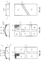
- Fig. 1 shows a top plan view of a burner with two burner deck parts;
- Fig. 2 shows a bottom plan view of a burner according to Fig. 1, with partly cutaway pressure distributing plates;
- Fig. 3 shows a cross-sectional view taken on the line III-III in Fig. 1;
- Fig. 4 shows a cross-sectional view taken on the line IV-IV in Fig. 1; and
- Figs. 5A-5E show a number of alternative shapes and arrangements for a burner deck.
- Fig. 1 shows in top plan view a
burner 1, provided with ahousing 2 and aburner deck 3. Thehousing 2 comprises, as appears in particular from Figs. 3 and 4, two verticallongitudinal walls 4 extending parallel to each other, and twoend walls 5, likewise extending approximately vertically and parallel to each other, which interconnect thelongitudinal walls 4 to each other at the ends thereof. Thehousing 2 is therefore substantially box-shaped and open towards the underside. Theend walls 5 have a curved upper side. Thelongitudinal walls 4 and theend walls 5 are outwardly flanged at their underside, so as to form acircumferential flange 6 for securing theburner 1 in a burner device. - Extending inwardly from the top of the
longitudinal walls 4 is an inclined firstdeck edge part 9, approximately parallel to a part of the upper side of theend walls 5. Extending inwardly from the top of theend walls 5 in approximately horizontal direction is a seconddeck edge part 10. The first and seconddeck edge parts circumferential deck edge 11. Adjacent the middle of thelongitudinal walls 4 the firstdeck edge parts 9 are interconnected through acurved bridge 12 which has a bending radius approximately equal to the bending radius of the upper side of theend walls 5. Accordingly, thedeck edge 11, together with thebridge 12, defines a surface forming a part of the circumferential surface of a cylinder. This surface is theburner deck 3, or at least similar in shape thereto. - In the embodiment shown in Fig. 1, the
burner deck 3 comprises twoburner deck parts 7, each approximately rectangular and provided with rows and columns ofoutflow openings 8. The configuration of theburner deck parts 7 will be further discussed hereinafter. - The inwardly facing
free edges 13 of thedeck edge 11 and thebridge 12 together describe one of theopenings 14 in which aburner deck part 7 is received. These free edges are designed as, or at least provided with, slidingguidance wings 15, in which thefree edges 30 of theburner deck parts 7 are movably confined with a proper fit. As a result of this confinement, theburner deck parts 7 can freely expand, shrink and move in their own plane but cannot move in any other direction. This is of importance in particular during the heating and cooling of theburner deck parts 7 and thehousing 2 during use. As a result, stresses, damage and deformations in theburner deck parts 7 are prevented, so that their life and reliability are increased. This is of great importance, in particular for modulating burners, in view of the varying mechanical and thermal loads of the parts. - In burners of the subject type, it is of importance that a relatively large burner deck is obtained which is preferably supplied from one housing, while further the cost price, the quality and the life thereof are of great importance. A
large burner deck 3 in a one-piece design has a disadvantage in that the deformations that may occur are relatively large as well, and hence are difficult to accommodate. Owing to the burner deck in a burner according to the invention being subdivided into smaller burner deck parts, which are supported on all sides in the slidingguidance wings 15, deformations can more simply be accommodated. As a result, theburner deck parts 3 can be manufactured more cheaply and/or better and/or from other, better materials. For instance, thinner plate material can be used than with the known burner, less stiff or less bearing material can be used, or material having a higher coefficient of expansion. Moreover, different burner deck parts can be combined. This will be reverted to in the discussion of the configuration of the burner deck parts. - With burners of the present type, it is advantageous when during use gas or a gas/air mixture cannot flow directly from the interior of the housing or from a supply channel to the
outflow openings 8 of theburner deck parts 7, for instance because as a result a poor combustion or too regular a flame pattern across the burner deck is obtained. In order to interrupt such influx, theburner 1 is provided with a number ofpressure distributing plates 16. In the embodiment shown in Figs. 1-4, twosuch plates 16 are arranged one above the other, under theburner deck 3. Fig. 2 shows these twoplates 16 within theburner 1 in bottom plan view. - The two
pressure distributing plates 16 substantially have a curved shape which corresponds approximately with the shape of the plane of theburner deck 3. The lower pressure distributing plate 16'', that is, the plate located farthest from theburner deck 3, is provided at the longitudinal edges thereof with a downwardlyflanged edge 17 through which the plate 16'' has been secured against the inside of thelongitudinal walls 4 and endwalls 5 in sealing engagement therewith. In a central area a multiplicity of evenly distributedthroughflow openings 18 have been provided. Thesethroughflow openings 18 all have one preferred embodiment and all have the same throughflow area. - Arranged side by side between the lower pressure distributing plate 16'' and the
burner deck 3 are two upper pressure distributing plates 16' which are provided in the central area thereof with a deepenedportion 19 having substantially the same dimensions as aburner deck part 7 and arranged straight under it. The edges of the upper pressure distributing plate 16' abut against the underside of thedeck edge 11 and thebridge 12 and together therewith form at least a part of the slidingguidance wings 15. In the bottom of the deepened portion 19 a number of rows and columns ofsecond throughflow openings 20 are provided. The distances between thesecond throughflow openings 20 are not always the same in the rows and/or the columns, while moreover the surfaces of thesecond throughflow openings 20 are not always the same. As a result, an irregular or at least a non-uniform pattern of second throughflow openings is obtained. 'Non-uniform' should herein be understood to mean different in, for instance, mutual distance and/or size and/or shape and/or direction of throughflow, the arrangement being such that the flow pattern of the gas or gas/air mixture on the side of the upper pressure distributing plates 16' proximal to theburner deck 3 is not the same everywhere as the gas flows through thesecond throughflow openings 20. - The lower pressure distributing plate 16'' is provided with a number of
spacers 21 extending above the plane of the pressure distributing plate 16'' and abutting against the underside of the deepenedportion 19 of the upper pressure distributing plates 16'. The upper pressure distributing plates 16'' are likewise provided withspacers 21, which abut against the underside of theburner deck parts 7. By thespacers 21, a fixed distance between thepressure distributing plates 16 mutually and between the upper pressure distributing plates 16' and the respectiveburner deck parts 7 is maintained and moreover the upper pressure distributing plates 16' and theburner deck parts 7 are supported. These fixed distances are of importance for a good regulation of the supply of the gas or gas/air mixture to theoutflow openings 8 and hence for the flame pattern during use. This will be further explained in the discussion of the configuration of the burner deck parts. - In the embodiment shown in Fig. 1, the
outflow openings 8 in theburner deck parts 7 are grouped inclusters 22, whichclusters 22 are separated from each other byintermediate edges 23. The clusters comprise twenty-fouroutflow openings 8 arranged in a regular pattern. By theintermediate edges 23 eachburner deck part 7 is reinforced and moreover an outflow opening pattern non-uniformly distributed over the burner deck is obtained. During use of a burner according to the invention, it can be particularly advantageous when the flame pattern above the burner deck is not the same throughout. As a result, inter alia undue noise production is counteracted, which is agreeable in particular for the user. In known burners such a flame pattern can lead to undesired material stresses and damage. In a burner according to the invention, this is simply prevented, inter alia as a result of the different, relatively small burner deck parts. Such a non-uniform flame pattern can be obtained and/or enhanced in a burner according to the invention, inter alia through the above-described features such as pressure distributing plates, non-uniform distribution of throughflow openings and outflow openings and a burner deck divided into burner deck parts, while the burner deck parts can be different. Each of these features can be used separately or in combination with other features. Theoutflow openings 8 can be provided over the entire surface of theburner deck parts 7 or only over a part thereof, for instance a central area selected such that theedges 30 which are received in the slidingguidance wings 15 are massive or at least free of outflow openings. - A burner according to the invention functions as follows.
- A combustible gas or preferably a gas/air mixture is supplied to the housing from, for instance, a blowing device which functions as a pre-mix device. The gas/air mixture is supplied in modulating manner and is forced through the
first throughflow openings 18 in the lower pressure distributing plate 16'', distributed between the twopressure distributing plates 16 and diverted in the direction of flow, in the direction of thesecond throughflow openings 20 in the upper pressure distributing plates 16'. The pressure distributing plate or plates in a burner according to the invention provide, among other things, for a mixing and distribution of the gas or gas/air mixture, and/or for the creation of pressure differences therein. In the deepenedportion 19 the irregularly supplied gas/air mixture is again adjusted in flow direction and flow velocity and thereafter forced through theoutflow openings 8, where it is burnt above theburner deck parts 7. Theburner deck parts 7 are thereby heated strongly, optionally to the point of being red hot, so that theburner deck parts 7 expand in a direction parallel to their own plane. Since theburner deck parts 7 can move in the slidingguidance wings 15 and expand relatively little with respect to the dimensions of theburner deck 3 as a result of their small dimensions, such expansion can readily be taken up. Accordingly, upon subsequent cooling, the burner deck can readily assume its original shape again. Owing to the confinement of the burner deck parts on all sides, the burner deck parts can be made of relatively little stiff design without this adversely affecting the action, the quality or the life of the burner. On the contrary, the relatively slight stiffness of the burner deck parts actually contributes to a long life of the burner. In particular a limitation of the length of theburner deck parts 7 entails a marked improvement of the life of the burner, since the greatest problems due to expansion will occur in the longitudinal direction. - The
burner deck parts 7 can be formed, for instance, from perforated metal sheet, or from ceramic or mesh material. The burner deck parts can be manufactured from known superalloys which exhibit a high tensile strength and slight expansion at high temperatures, but precisely with burner deck parts according to the invention is it advantageous to use cheaper alloys such as iron-chromium-aluminum alloys or still cheaper alloys such as chromium-steel alloys, which are particularly suitable for gauze-shaped burner deck parts. - Figs. 5A-5E show in top plan view and in sectional side elevation a series of burner deck arrangements which are possible while using features according to the invention. Fig. 5A, for instance, shows a burner deck with a curved top surface, which consists of four rectangular
burner deck parts 7A, while in addition to abridge 12 between the sidewalls 4 a bridge 12' between theend walls 5 is included. In this embodiment theoutflow openings 8 are slotted. - Fig. 5B shows a comparable burner deck, which, however, is provided with two
bridges 12 between thelongitudinal walls 4 and one bridge 12' between theend walls 5, so that sixburner deck parts 7B are obtained, which do not all have the same dimensions. In this embodiment, the top surface of the burner deck is not curved but angled, while theburner deck parts 7B are flat. This provides advantages from the point of view of manufacturing technique, in particular when using material for theburner deck parts 7 which is not easy to deform, such as ceramic plates, or which in curved condition would deform too strongly or uncontrollably upon heat loads. By arranging several flat burner deck parts side by side, with juxtaposed burner deck parts mutually including an angle, it is even possible to thereby obtain a substantially circular arc-shaped or cylindrical burner deck. Due to the unequal dimensions of the burner deck parts, it is possible to enhance or obtain the irregularity of the flame pattern during use. Moreover, the angled burner deck can in some cases provide advantages in the burner pattern. In this embodiment theoutflow openings 8 are alternately slotted and circular. - Fig. 5C shows an embodiment where the burner deck is divided in two
burner deck parts 7C, which have a trapezoidal shape in that thebridge 12 has been arranged obliquely relative to the longitudinal direction of the burner, between thelongitudinal walls 4. - Fig. 5D shows an embodiment of a burner according to the invention where the housing is approximately circular and the
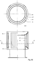
burner deck 3 has a doubly curved surface. Theburner deck 3 is divided by threebridges 12 into six identically shaped, triangular flat burner deck parts. A circular housing has as an advantage that the burner deck is large with respect to the circumferential wall of the housing, compared with a rectangular burner having a comparable burner deck surface. This means that less material is needed for such a burner housing. Moreover, such a burner is simple to manufacture. Of course, the triangular burner deck parts can also be curved in one or in two directions. - Fig. 5E shows in partial cross section a cylindrical burner where the
burner deck 3 substantially constitutes the superficies or shell of the burner. Fourbridges 12 extend parallel to the longitudinal direction of the burner in, or at least parallel to, the superficies. Theburner deck parts 7E are disposed between thebridges 12, likewise in the superficies, and in the embodiment shown are curved in one direction. Further, two concentrically arranged pressure distributing plates 16' and 16'' are included within the burner, which in function and design further correspond substantially with the earlier describedpressure distributing plates 16. The height of the inner pressure distributing plate 16'' is slightly less than the height of the outer pressure distributing plate 16', which has a height approximately corresponding with the height of theburner deck parts 7E. Theburner deck parts 7 in the embodiments shown in Figs. 5A-5E naturally have their edges retained in sliding wings. This burner is closed at the top by a cover 24 whose edges have been flanged over the outside of the superficies and secured thereto. Of course, other closures are also possible. At the underside, located opposite, a supply opening 25 is formed by a neck part 26 extending downwards in the shape of a tube, which adjacent the free end thereof is provided with anannular securing flange 6. Through the supply opening 25 gas or a gas/air mixture can be supplied during use. Within the burner, for instance a distributing cone may be further included. - In embodiments not shown, it is possible, in the case of a shell-shaped
burner deck 3, for theburner deck parts 7E to be of entirely flat design, so that an at least partly facetted burner deck is obtained, while also burner deck parts can be arranged above each other. Moreover, the top of such a burner can also be provided with one or more burner deck parts and the burner can have the shape of a segment of a sphere or ellipsoid. - The invention is not in any way limited to the embodiments shown in the drawing and described in the description. Many variations thereof are possible.
- Thus, in some cases, the burner deck can have a different outer shape, for instance curved or polygonal. Moreover, other burner deck arrangements can be used than those shown by way of example only. Instead of the two pressure distributing plates, a different number can be chosen; other pressure distributing means can be used or they can be omitted. Moreover, the throughflow openings and/or the outflow openings can be differently grouped, positioned and/or shaped. Thus, for instance, the outflow openings or the throughflow openings can be provided with diverting means for changing the direction of the gas/air mixture flow. Also, they can be made, for instance, of venturi-shaped design. The burner deck can be provided with closed parts, for instance a closed top surface over the length of the burner, with a number of burner deck parts on opposite sides, and moreover can be made, for instance, of flat or concave design. The housing can of course be adapted to the desired application as to material use and design in a variety of ways.
- These and many comparable modifications and variations are understood to fall within the scope of the invention.
Claims (15)
- A burner for use in a gas-fired burner device, comprising a housing at least partly covered by a burner deck provided with outflow openings for allowing, during use, the passage of a gas or gas/air mixture from the inside of the housing to the environment, with the circumferential edges of the burner deck being retained so as to be movable with respect to the housing, characterized in that the burner deck comprises a series of burner deck parts arranged next to each other, which burner deck parts each comprise a row of outflow openings in communication with the inside of the housing, while between burner deck parts arranged next to each other bridges are included which are fixedly connected with the housing, in which bridges the facing edges of the burner deck parts connecting thereto are movably retained, the arrangement being such that during use each burner deck part can deform at least in the plane of the burner deck part in question, independently of the other burner deck parts, the housing and the bridges.
- A burner according to claim 1, characterized in that the housing has substantially a rectangular basic shape, with two longitudinal walls and two end walls interconnecting the facing ends of the longitudinal walls, the end walls being relatively short with respect to the longitudinal walls, and at least one bridge extends between the longitudinal walls, spaced from the end walls.
- A burner according to claim 1, characterized in that the housing comprises two longitudinal walls and two end walls interconnecting the facing ends of the longitudinal walls, the end walls being relatively short with respect to the longitudinal walls, and at least one bridge extends between the end walls, spaced from the longitudinal walls.
- A burner according to claim 1, characterized in that the housing comprises two longitudinal walls and two end walls interconnecting the facing ends of the longitudinal walls, with at least one bridge extending between the end walls, spaced from the longitudinal walls, and at least one bridge extending between the longitudinal walls, spaced from the end walls.
- A burner according to claim 1, characterized in that the housing is substantially cylindrical, with at least a part of the cylindrical circumferential wall being formed by the burner deck.
- A burner according to any one of claims 1-5, characterized in that under the burner deck at least one pressure distributing means is arranged, which is preferably plate-shaped, provided with at least one row of throughflow openings, which pressure distributing plate extends under all burner deck parts.
- A burner according to claim 6, characterized in that at least a number of mutual distances between successive throughflow openings in at least one row are different and preferably form an irregular row.
- A burner according to claim 6 or 7, characterized in that at least a number of the surfaces of successive throughflow openings in at least one row are different and preferably form an irregular row.
- A burner according to any one of claims 6-8, characterized in that the throughflow openings in at least one pressure distributing plate located adjacent the burner deck are provided substantially in clustered arrangement under the burner deck parts.
- A burner according to any one of the preceding claims, characterized in that the outflow openings are distributed over the burner deck in rows and columns, while the mutual distances between and/or the surfaces of successive outflow openings in the rows and/or the columns are different and preferably form irregular rows and columns.
- A burner according to any one of the preceding claims, characterized in that the outflow openings are provided in clustered distribution over the burner deck parts.
- A burner according to any one of the preceding claims, characterized in that a number of burner deck parts, and preferably all burner deck parts, are manufactured from perforated metal sheet.
- A burner according to any one of the preceding claims, characterized in that a number of burner deck parts, and preferably all burner deck parts, are manufactured from ceramic material.
- A burner according to any one of the preceding claims, characterized in that at least one of the burner deck parts has a surface of different dimensions from at least a number of the other burner deck parts.
- A gas-fired burner device comprising at least one burner according to any one of the preceding claims.
Applications Claiming Priority (2)
| Application Number | Priority Date | Filing Date | Title |
|---|---|---|---|
| NL1001688 | 1995-11-17 | ||
| NL1001688A NL1001688C2 (en) | 1995-11-17 | 1995-11-17 | Burner with segmented burner deck. |
Publications (1)
| Publication Number | Publication Date |
|---|---|
| EP0774623A1 true EP0774623A1 (en) | 1997-05-21 |
Family
ID=19761877
Family Applications (1)
| Application Number | Title | Priority Date | Filing Date |
|---|---|---|---|
| EP96203215A Withdrawn EP0774623A1 (en) | 1995-11-17 | 1996-11-18 | Burner with segmented burner deck |
Country Status (2)
| Country | Link |
|---|---|
| EP (1) | EP0774623A1 (en) |
| NL (1) | NL1001688C2 (en) |
Cited By (10)
| Publication number | Priority date | Publication date | Assignee | Title |
|---|---|---|---|---|
| EP0816757A3 (en) * | 1996-07-05 | 1999-03-31 | Schwank GmbH | Burner element |
| EP0915293A2 (en) * | 1997-11-06 | 1999-05-12 | Robert Bosch Gmbh | Forced draught burner |
| NL1018054C2 (en) * | 2001-05-11 | 2002-11-12 | Dejatech Bv | Assembly of a burner and a burner housing. |
| WO2004111536A1 (en) | 2003-06-19 | 2004-12-23 | Worgas Bruciatori S.R.L. | Burner with diffuser resistant to high operating temperatures |
| WO2006045426A3 (en) * | 2004-10-22 | 2006-07-06 | Worgas Bruciatori Srl | Burner with diffuser resistant to high operating temperatures |
| WO2008081271A2 (en) * | 2006-12-22 | 2008-07-10 | Worgas - Bruciatori - S.R.L. | Burner with diffuser resistant to high operating temperatures |
| JP2011511242A (en) * | 2008-01-28 | 2011-04-07 | テトゥラ・ラバル・ホールディングス・アンド・ファイナンス・ソシエテ・アノニム | Gas burner |
| ITMI20101981A1 (en) * | 2010-10-26 | 2012-04-27 | Worgas Bruciatori Srl | BURNER FOR GAS BOILER |
| EP4163544A1 (en) | 2021-10-07 | 2023-04-12 | BDR Thermea Group B.V. | Burner deck and process of manufaturing thereof |
| WO2024013046A1 (en) * | 2022-07-11 | 2024-01-18 | Bekaert Combustion Technology B.V. | Premix gas burner and method for manufacturing a premix gas burner |
Citations (9)
| Publication number | Priority date | Publication date | Assignee | Title |
|---|---|---|---|---|
| US3556707A (en) * | 1969-06-05 | 1971-01-19 | Luxaire Inc | Gas-fired radiant heater |
| FR2503836A1 (en) * | 1981-04-10 | 1982-10-15 | Vaneecke Solaronics | Large area multiple flame burner - has perforated ceramic block supported at metal housings and with retaining rods |
| US4397631A (en) * | 1980-09-08 | 1983-08-09 | The Carlin Company | Pre-mix forced draft power gas burner |
| EP0314897A1 (en) * | 1987-10-31 | 1989-05-10 | Ruhrgas Aktiengesellschaft | Excess-air premix gas burner for gas heating devices |
| DE8914388U1 (en) * | 1988-12-21 | 1990-01-25 | Joh. Vaillant Gmbh U. Co, 5630 Remscheid, De | |
| US5022352A (en) * | 1990-05-31 | 1991-06-11 | Mor-Flo Industries, Inc. | Burner for forced draft controlled mixture heating system using a closed combustion chamber |
| EP0451923A2 (en) * | 1990-04-12 | 1991-10-16 | Dru B.V. | Burner |
| WO1992012381A1 (en) * | 1991-01-07 | 1992-07-23 | Ruhrgas Aktiengesellschaft | Gas burner and method of operating it |
| DE29505906U1 (en) * | 1995-04-06 | 1995-07-20 | Buderus Heiztechnik Gmbh | Device for fastening a burner plate |
-
1995
- 1995-11-17 NL NL1001688A patent/NL1001688C2/en not_active IP Right Cessation
-
1996
- 1996-11-18 EP EP96203215A patent/EP0774623A1/en not_active Withdrawn
Patent Citations (9)
| Publication number | Priority date | Publication date | Assignee | Title |
|---|---|---|---|---|
| US3556707A (en) * | 1969-06-05 | 1971-01-19 | Luxaire Inc | Gas-fired radiant heater |
| US4397631A (en) * | 1980-09-08 | 1983-08-09 | The Carlin Company | Pre-mix forced draft power gas burner |
| FR2503836A1 (en) * | 1981-04-10 | 1982-10-15 | Vaneecke Solaronics | Large area multiple flame burner - has perforated ceramic block supported at metal housings and with retaining rods |
| EP0314897A1 (en) * | 1987-10-31 | 1989-05-10 | Ruhrgas Aktiengesellschaft | Excess-air premix gas burner for gas heating devices |
| DE8914388U1 (en) * | 1988-12-21 | 1990-01-25 | Joh. Vaillant Gmbh U. Co, 5630 Remscheid, De | |
| EP0451923A2 (en) * | 1990-04-12 | 1991-10-16 | Dru B.V. | Burner |
| US5022352A (en) * | 1990-05-31 | 1991-06-11 | Mor-Flo Industries, Inc. | Burner for forced draft controlled mixture heating system using a closed combustion chamber |
| WO1992012381A1 (en) * | 1991-01-07 | 1992-07-23 | Ruhrgas Aktiengesellschaft | Gas burner and method of operating it |
| DE29505906U1 (en) * | 1995-04-06 | 1995-07-20 | Buderus Heiztechnik Gmbh | Device for fastening a burner plate |
Cited By (18)
| Publication number | Priority date | Publication date | Assignee | Title |
|---|---|---|---|---|
| EP0816757A3 (en) * | 1996-07-05 | 1999-03-31 | Schwank GmbH | Burner element |
| EP0915293A2 (en) * | 1997-11-06 | 1999-05-12 | Robert Bosch Gmbh | Forced draught burner |
| EP0915293A3 (en) * | 1997-11-06 | 1999-11-17 | Robert Bosch Gmbh | Forced draught burner |
| NL1018054C2 (en) * | 2001-05-11 | 2002-11-12 | Dejatech Bv | Assembly of a burner and a burner housing. |
| EP1256760A1 (en) * | 2001-05-11 | 2002-11-13 | Dejatech B.V. | Assembly of a burner and a burner housing |
| EP2484974A3 (en) * | 2003-06-19 | 2014-08-27 | Worgas Bruciatori S.R.L. | Burner with diffuser resistant to high operating temperatures |
| EP2484974A2 (en) | 2003-06-19 | 2012-08-08 | Worgas Bruciatori S.R.L. | Burner with diffuser resistant to high operating temperatures |
| WO2004111536A1 (en) | 2003-06-19 | 2004-12-23 | Worgas Bruciatori S.R.L. | Burner with diffuser resistant to high operating temperatures |
| WO2006045426A3 (en) * | 2004-10-22 | 2006-07-06 | Worgas Bruciatori Srl | Burner with diffuser resistant to high operating temperatures |
| WO2008081271A2 (en) * | 2006-12-22 | 2008-07-10 | Worgas - Bruciatori - S.R.L. | Burner with diffuser resistant to high operating temperatures |
| WO2008081271A3 (en) * | 2006-12-22 | 2008-08-28 | Worgas Bruciatori Srl | Burner with diffuser resistant to high operating temperatures |
| JP2011511242A (en) * | 2008-01-28 | 2011-04-07 | テトゥラ・ラバル・ホールディングス・アンド・ファイナンス・ソシエテ・アノニム | Gas burner |
| US9004913B2 (en) | 2008-01-28 | 2015-04-14 | Tetral Laval Holdings & Finance S.A. | Gas burner |
| ITMI20101981A1 (en) * | 2010-10-26 | 2012-04-27 | Worgas Bruciatori Srl | BURNER FOR GAS BOILER |
| EP4163544A1 (en) | 2021-10-07 | 2023-04-12 | BDR Thermea Group B.V. | Burner deck and process of manufaturing thereof |
| WO2023057605A1 (en) | 2021-10-07 | 2023-04-13 | Bdr Thermea Group B.V. | Burner deck and process of manufaturing thereof |
| WO2024013046A1 (en) * | 2022-07-11 | 2024-01-18 | Bekaert Combustion Technology B.V. | Premix gas burner and method for manufacturing a premix gas burner |
| NL2032443B1 (en) * | 2022-07-11 | 2024-01-23 | Bekaert Combustion Tech Bv | Premix gas burner and method for manufacturing a premix gas burner |
Also Published As
| Publication number | Publication date |
|---|---|
| NL1001688C2 (en) | 1997-05-21 |
Similar Documents
| Publication | Publication Date | Title |
|---|---|---|
| EP0774623A1 (en) | Burner with segmented burner deck | |
| AU621093B2 (en) | Improvements to gas burners | |
| US5899686A (en) | Gas burner apparatus having a flame holder structure with a contoured surface | |
| CA2019123C (en) | Ceramic gas burner for a hot blast stove, and bricks therefor | |
| KR20110104080A (en) | A metal burner membrane | |
| EP1809946B1 (en) | Improved gas burner system for food cooking | |
| EP3343104B1 (en) | Distributed vertical flame burner | |
| US5997285A (en) | Burner housing and plenum configuration for gas-fired burners | |
| EP0797048B1 (en) | Gas burner for kitchen appliances | |
| CN104541103A (en) | Surface-combustion gas burner | |
| CA1319575C (en) | Hot water production appliances | |
| US4292274A (en) | Catalytic reactor with improved burner | |
| US5057007A (en) | Low nox atmospheric gas burner | |
| US3185069A (en) | Air distribution devices | |
| US5176512A (en) | Inshot burner cluster apparatus | |
| WO1995027871A1 (en) | Metal fiber membrane for gas burners | |
| NL1005382C1 (en) | Gas burner. | |
| RU1807977C (en) | Ceramic member for facing regenerators of glassmaking furnaces | |
| US3136354A (en) | Radiant gas burners | |
| EP1634018B1 (en) | Burner with diffuser resistant to high operating temperatures | |
| US3179157A (en) | Deep combustion radiant surface gas burner | |
| US1884557A (en) | Fuel grate | |
| JP2002206711A (en) | Cooker burner | |
| US2966211A (en) | Gas burner | |
| US4308910A (en) | Checkerwork supporting means |
Legal Events
| Date | Code | Title | Description |
|---|---|---|---|
| PUAI | Public reference made under article 153(3) epc to a published international application that has entered the european phase |
Free format text: ORIGINAL CODE: 0009012 |
|
| AK | Designated contracting states |
Kind code of ref document: A1 Designated state(s): AT BE CH DE DK ES FR GB GR IE IT LI LU MC NL PT SE |
|
| RAP1 | Party data changed (applicant data changed or rights of an application transferred) |
Owner name: FURIGAS ASSEN B.V. |
|
| 17P | Request for examination filed |
Effective date: 19971120 |
|
| RBV | Designated contracting states (corrected) |
Designated state(s): AT BE CH DE DK ES FR GB GR IE IT LI LU MC NL PT SE |
|
| STAA | Information on the status of an ep patent application or granted ep patent |
Free format text: STATUS: THE APPLICATION IS DEEMED TO BE WITHDRAWN |
|
| 18D | Application deemed to be withdrawn |
Effective date: 19990601 |