EP0774596B1 - Bremsgestänge, dass einen Coulomb-Dämpfer zur Biegung enthält - Google Patents
Bremsgestänge, dass einen Coulomb-Dämpfer zur Biegung enthält Download PDFInfo
- Publication number
- EP0774596B1 EP0774596B1 EP96117718A EP96117718A EP0774596B1 EP 0774596 B1 EP0774596 B1 EP 0774596B1 EP 96117718 A EP96117718 A EP 96117718A EP 96117718 A EP96117718 A EP 96117718A EP 0774596 B1 EP0774596 B1 EP 0774596B1
- Authority
- EP
- European Patent Office
- Prior art keywords
- rod
- bending mode
- reference plane
- shear center
- misalignment
- Prior art date
- Legal status (The legal status is an assumption and is not a legal conclusion. Google has not performed a legal analysis and makes no representation as to the accuracy of the status listed.)
- Expired - Lifetime
Links
Images


Classifications
-
- F—MECHANICAL ENGINEERING; LIGHTING; HEATING; WEAPONS; BLASTING
- F16—ENGINEERING ELEMENTS AND UNITS; GENERAL MEASURES FOR PRODUCING AND MAINTAINING EFFECTIVE FUNCTIONING OF MACHINES OR INSTALLATIONS; THERMAL INSULATION IN GENERAL
- F16D—COUPLINGS FOR TRANSMITTING ROTATION; CLUTCHES; BRAKES
- F16D65/00—Parts or details
- F16D65/0006—Noise or vibration control
-
- F—MECHANICAL ENGINEERING; LIGHTING; HEATING; WEAPONS; BLASTING
- F16—ENGINEERING ELEMENTS AND UNITS; GENERAL MEASURES FOR PRODUCING AND MAINTAINING EFFECTIVE FUNCTIONING OF MACHINES OR INSTALLATIONS; THERMAL INSULATION IN GENERAL
- F16D—COUPLINGS FOR TRANSMITTING ROTATION; CLUTCHES; BRAKES
- F16D55/00—Brakes with substantially-radial braking surfaces pressed together in axial direction, e.g. disc brakes
- F16D55/24—Brakes with substantially-radial braking surfaces pressed together in axial direction, e.g. disc brakes with a plurality of axially-movable discs, lamellae, or pads, pressed from one side towards an axially-located member
- F16D55/26—Brakes with substantially-radial braking surfaces pressed together in axial direction, e.g. disc brakes with a plurality of axially-movable discs, lamellae, or pads, pressed from one side towards an axially-located member without self-tightening action
- F16D55/36—Brakes with a plurality of rotating discs all lying side by side
-
- F—MECHANICAL ENGINEERING; LIGHTING; HEATING; WEAPONS; BLASTING
- F16—ENGINEERING ELEMENTS AND UNITS; GENERAL MEASURES FOR PRODUCING AND MAINTAINING EFFECTIVE FUNCTIONING OF MACHINES OR INSTALLATIONS; THERMAL INSULATION IN GENERAL
- F16F—SPRINGS; SHOCK-ABSORBERS; MEANS FOR DAMPING VIBRATION
- F16F7/00—Vibration-dampers; Shock-absorbers
- F16F7/08—Vibration-dampers; Shock-absorbers with friction surfaces rectilinearly movable along each other
- F16F7/09—Vibration-dampers; Shock-absorbers with friction surfaces rectilinearly movable along each other in dampers of the cylinder-and-piston type
-
- F—MECHANICAL ENGINEERING; LIGHTING; HEATING; WEAPONS; BLASTING
- F16—ENGINEERING ELEMENTS AND UNITS; GENERAL MEASURES FOR PRODUCING AND MAINTAINING EFFECTIVE FUNCTIONING OF MACHINES OR INSTALLATIONS; THERMAL INSULATION IN GENERAL
- F16D—COUPLINGS FOR TRANSMITTING ROTATION; CLUTCHES; BRAKES
- F16D55/00—Brakes with substantially-radial braking surfaces pressed together in axial direction, e.g. disc brakes
- F16D2055/0004—Parts or details of disc brakes
- F16D2055/0058—Fully lined, i.e. braking surface extending over the entire disc circumference
Definitions
- the invention relates to the field of braking systems, particularly those braking systems that utilize linkages to transmit brake-generated loads from a wheel and brake assembly to a braked vehicle.
- Vehicle braking systems are one of a class of mechanisms that can be induced to vibrate by the action of friction. In some situations, the. vibration may become unstable and grow to levels severe enough to cause excessive noise, passenger discomfort, and/or structural failure of system components. Part of the art of designing such systems lies in increasing the stabilizing effects of damping within and between the components of the system to counteract the destabilizing effects of braking friction.
- the invention applies to any member of a general class of braking systems that use linkages to transmit brake-generated loads from the wheel and brake to the braked vehicle. It is particularly useful with multi-brake aircraft landing gear systems.
- the wheel and brake assemblies are typically mounted in pairs on two or more tandem axles, which are in turn fixed to a "bogie” or “truck” beam that pivots about a point on the inner cylinder of the landing gear's shock strut.
- the brake torque generated by each of the fore and aft assemblies is reacted by forces at its axle and through a brake rod that links the brake to the inner cylinder of the landing gear at a point above or below the bogie pivot.
- the fore brake rods act in compression and the aft rods act in tension to transmit braking forces to the bogie.
- the rod forms one of the four links of a parallel four-bar linkage that operates in the pitch plane of the aircraft.
- Figure 1 is a side view of a damped member according to an aspect of the invention attached to a pair of masses.
- Figure 2 is a cross-section view of a damped member according to an aspect of the invention along line A-A of Figure 1.
- Figure 3 is a cross-section view of a damped member according to another aspect of the invention along line A-A of Figure 1.
- Figure 4 is a cross-section view of a damped member according to another aspect of the invention along line A-A of Figure 1.
- Figure 5 is a cross-section view of a damped member according to another aspect of the invention along line A-A of Figure 1.
- Figure 6 is a cross-section view of a damped member according to another aspect of the invention along line A-A of Figure 1.
- Figure 7 is a cross-section view of a damped member according to another aspect of the invention along line A-A of Figure 1.
- Figure 8 is a cross-section view of a damped member according to another aspect of the invention along line A-A of Figure 1.
- Figure 9 is a side view of a section of a damping member according to an aspect of the invention.
- Figure 10 is a cross-section view of a damped member according to another aspect of the invention along line A-A of Figure 1.
- Figure 11 is a cross-section view of a damped member according to another aspect of the invention along line A-A of Figure 1.
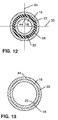
- Figure 12 is a cross-section view of a damped member according to another aspect of the invention along line A-A of Figure 1.
- Figure 13 is a cross-section view of a damped member according to another aspect of the invention along line A-A of Figure 1.
- Figure 14 is a schematic view of typical prior art landing gear assembly.
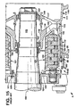
- Figure 15 is a sectional view of a typical prior art wheel and brake assembly.
- Figure 16 is a side view of a damped brake rod according to an aspect of the invention, with parts broken away.
- Figure 17 is a sectional view of a damped torque tube according to an aspect of the invention.
- Figure 18 is a cross-sectional view of the Figure 17 torque tube along line C-C of Figure 17.
- FIG. 1-13 Several embodiments illustrating various aspects of the invention are presented in Figures 1-13, which are not drawn to scale, and wherein like numbered components and features are numbered alike.
- a structural member 10 is presented that carries a load between a first mass 12 and a second mass 14.
- the load may place the structural member 10 in one or more of tension, compression, and torsion.
- the structural member 10 may be attached to the first and second masses 12 and 14 by means known in the mechanical arts, in a manner that allows the structural member 10 to carry a load between the first and second masses 12 and 14.
- the mode of attachment may permit or prevent relative rotation of the structural member 10 relative to the first and second masses 12 and 14, depending on type of load to be carried.
- the structural member 10 comprises a load-carrying member 16 for carrying the load between the first and second masses 12 and 14, and at least one damping member 20 nested with the load-carrying member 16.
- the load-carrying member 16 and damping member 20 may be formed from materials typically used for structural load bearing applications, such as metals, including steel alloys and aluminum and its alloys, and fiber reinforced plastic composites, including glass fiber reinforced epoxies and carbon fiber reinforced epoxies. The materials listed are disclosed as examples of suitable materials, and it is not intended to limit the invention to a specific material.
- the damping member 20 may have an axial length less than, equal to, or greater than the length of the load-carrying member 16, depending on the particular application of the invention.
- the damping member 20 and the load-carrying member 16 move relative to each other during cyclic distortion or vibration of the load-carrying member 16 thereby dissipating distortion energy at a damping interface between the damping member 20 and the load-carrying member 16.
- the damping interface comprises frictional contact between two surfaces. This type of damping is generally known as "coulomb damping.”
- the Figure 2 embodiment utilizes coulomb damping.
- the damping interface may comprise a constrained viscoelastic damping layer disposed between the load-carrying member 16 and the damping member 20. This embodiment will be discussed with more detail in relation to Figure 12.
- the actual load is transferred through the load-carrying member 16 rather than the damping member 20, according to an aspect of the invention.
- Loading of the damping member 20 consists essentially of cyclic distortion or vibration loads induced by cyclic distortion of the load-carrying member 16.
- the damping member is otherwise passive, meaning that the damping member 20 experiences "essentially" no loading in the absence of cyclic distortion or vibration of the load-carrying member 16.
- the load-carrying member 16 bears the actual load transferred between the first mass and the second mass, which may generate a cyclic distortion or vibration in the load-carrying member superposed upon the actual load.
- the actual load may be viewed as the average load transferred between the first mass 12 and second mass 14 during the load-carrying event.
- the damping member 20 bears essentially only cyclic loads induced by the cyclic bending mode movement or vibration of the load-carrying member 16.
- a small amount of the actual load carried between the first and second masses 12 and 14 by the load-carrying member 16 may be incidently transferred to the damping member 20 through the damping interface 20, and the term "essentially" is intended to encompass such effects.
- the coulomb damping embodiment of Figure 2 may be implemented by providing the load-carrying member 16 with an axially distributed circumferential surface 18, and by providing the damping member with a second surface 22 that engages the first surface 18.
- the first surface 18 and second surface may be generally coterminous.
- the term "axial" refers to the lengthwise direction, as indicated at 11 in Figure 1, and may or may not include the entire length of the referenced component.
- the damping interface comprises frictional contact between the first surface 18 and the second surface 22.
- the second surface 22 slides relative to the first surface 18 during cyclic distortion of the load-carrying member 16 thereby dissipating distortion energy at the damping interface between the first surface 18 and the second surface 22.
- the friction effect is small if the interference contact pressure between the load-carrying member 16 and damping member 20 is small.
- the additional bending effect is small if the bending stiffness of the damping member is small.
- the bending effect is non-existent if the distortion does not comprise a bending mode.
- the load-carrying member 16 receives the damping member 20 with an interference fit resulting in the second surface 22 pressing against the first surface 18.
- the interference pressure is preferably great enough to provide significant damping at low amplitudes, but low enough to allow relative sliding motion to occur between the two bodies in contact.
- the cyclic distortion that is damped at the damping interface may comprise various forms of distortion, including torsional modes and/or bending modes.
- the load-carrying member 16 For bending in a plane parallel to the axial direction 11, the load-carrying member 16 has a load-carrying member neutral axis 28, and the damping member 20 has a damping member neutral axis 26.
- the load-carrying member 16 also has a load-carrying member shear center 38 for the bending mode, and the damping member 20 has a damping member shear center 36 for the bending mode.
- at least a component of the bending mode may occur in a reference plane 24 parallel to the axial direction 11.
- An additional reference plane 30 is also presented, normal to the reference plane 24.
- Reference plane 24 and additional reference plane 30 are interchangeable, and are intended to provide a reference frame for purposes of defining the invention without limiting the invention to the specific orientations of the reference planes presented in the figures.
- the damping member neutral axis 26 and the load-carrying neutral axis 28 have a predetermined neutral axis misalignment 32, parallel to the reference plane 24.
- the neutral axis misalignment causes relative sliding movement between surfaces 18 and 22 during bending of the load-carrying member 10. This type of sliding action is referred to herein as "axial sliding" because it occurs in the axial direction.
- shifting the shear center of the load-carrying member 16 out of the plane of bending also causes relative sliding movement between surfaces 18 and 22 during distortion of the structural member 10. Still referring to Figure 2, at least a component of the bending mode may occur in the reference plane 30.
- the damping member shear center 36 and the load-carrying member shear center 38 have a predetermined shear center misalignment 40.
- the shear center misalignment 40 is normal to the reference plane 30. Shifting the load-carrying member shear center 38 out of the plane of bending causes the load-carrying member to twist during bending.
- shifting the damping member shear center 36 out of the plane of bending causes the damping member to twist during bending.
- the predetermined neutral axis misalignment 32 and predetermined shear center misalignment 40 are established by the cross-sections of the damping member 20 and load-carrying member 16.
- an axial slot 44 is provided that shifts both the neutral axis 26 and shear center 36 of the damping member 20 from the neutral axis 28 and shear center 38 of the load-carrying member.
- the cross-section of the damping member 20 depends on the cross-section of the load-carrying member 16 and the damping characteristics desired in the damped member 10. It is not intended to limit the invention to the specific cross-sections presented in the figures, since many cross-sections are evident to an artisan skilled in the art, and may be designed according to the principles provided herein. Any such variations are considered to fall within the purview the invention.
- FIG. 3 a cross-section of another embodiment of the invention along line A-A of Figure 1 is presented, wherein the damping member 20 is rotated on the order of 90° from the position presented in Figure 2.
- Relative sliding motion between the first and second surfaces 18 and 22 still occurs during bending of the load-carrying member 10 in both reference planes 24 and 30, but now bending in reference plane 24 produces rotational sliding due to shear center misalignment 40 normal the reference plane 24, and bending in reference plane 30 produces axial sliding due to neutral axis misalignment 30 parallel to reference plane 30.
- Rotating the damping member 20 to provide axial sliding versus rotational sliding in one reference plane versus another may optimize damping in one or both planes since each type of sliding may generate a different amount of damping, depending on the cross-section of the damping member 20, and the relative magnitudes of bending distortion.
- FIG 4 a cross-section of another embodiment of the Invention along line A-A of Figure 1 is presented.
- the damping member 20 is rotated less than 90° from the position presented in Figure 2. This orientation causes a combination of sliding effects for bending in both the reference plane 24 and the reference plane 30.
- the damping member neutral axis 26 and the load-carrying neutral axis 28 have a predetermined neutral axis misalignment 32. At least a component 33 of the predetermined neutral axis misalignment 32 is parallel to the reference plane 24, which causes relative axial sliding between first surface 18 and second surface 22 during bending in said first plane.
- the damping member shear center 36 and the load-carrying member shear center 38 have a predetermined shear center misalignment 40.
- At least a component 41 of the predetermined shear center misalignment 40 is normal to the reference plane 24.
- the component 41 of the shear center misalignment 40 causes relative rotational sliding between first surface 18 and second surface 22 during bending in the reference plane 24. Therefore, bending in the reference plane 24 causes a combination of axial sliding and rotational sliding.
- the reference plane 30 At least a component 34 of the predetermined neutral axis misalignment 32 is parallel to the reference plane 30, which causes relative axial sliding between first surface 18 and second surface 22 during bending in reference plane 30.
- At least a component 42 of the predetermined shear center misalignment 40 is normal to the additional reference plane 30, which causes relative rotational sliding between the first surface 18 and the second surface 22 during bending in reference plane 30. Therefore, bending in the reference plane 30 causes a combination of axial sliding and rotational sliding between first surface 18 and second surface 22.
- the damping effects of a coulomb damper according to the invention may be quantified through experiment and/or analysis.
- the predetermined neutral axis misalignment may provide a predetermined quantity of bending damping in a desired reference plane.
- the predetermined shear center misalignment may provide a predetermined quantity of bending damping in a desired reference plane.
- a predetermined neutral axis misalignment may be used with or without a predetermined shear center misalignment.
- a predetermined shear center misalignment may be used with or without a predetermined neutral axis misalignment.
- a predetermined neutral axis misalignment and predetermined shear center misalignment may be used together to provide a predetermined quantity of bending damping in a desired reference plane.
- the magnitude and orientation of a neutral axis misalignment and/or shear center misalignment may be manipulated and combined to provide a predetermined quantity of damping, and relative degree of damping, in each reference plane.
- the load-carrying member 16 and damping member 20 may cyclicly follow a deflection path 58 (shown in phantom) during the cyclic distortion.
- the deflection path 58 represents the path a point on the load-carrying member 16 or damping member 20 may follow during the cyclic distortion, and is shown greatly exaggerated in Figure 4 for the sake of clarity.
- the magnitude and orientation of the predetermined neutral axis misalignment 32 and predetermined shear center misalignment 40, along with the angular orientation of the damping member 20, may be manipulated and combined to provide a predetermined quantity of damping, and relative degree of damping, in each reference plane that optimally damps the cyclic distortion causing the deflection path 58.
- a damping member and load-carrying member may be designed having coincident neutral axes, and misaligned shear centers.
- the shear centers together define a reference plane, and bending in a plane normal to the reference plane is damped, while bending in a plane parallel to the reference plane is not damped.
- the bending damping is entirely due to rotational sliding induced by the shear center misalignment.
- the damping member 20 has a third surface 48 axially distributed along the damping member 20. At least a second damping member 50 is provided having a fourth surface 52 engaging the third surface 48. The fourth surface 52 slides against the third surface 48 during bending of the load-carrying member 16 thereby providing coulomb damping.
- the damping member 20 may receive the second damping member 50 with an interference fit that forces the fourth surface 52 against the third surface 48, thereby enhancing the coulomb damping effect.
- the second damping member 50 functions the same as the damping member 20, and the principles discussed in relation to Figures 1-4 also apply to the damping member 50.
- the neutral axis 60 of the damping member 50 and the neutral axis 26 of the damping member 20 may have a predetermined neutral axis misalignment 62, which induces relative axial sliding movement between the third surface 48 and the fourth surface 52.
- the shear center 64 of the damping member 50 the shear center 36 of the damping member 20 may also have a predetermined shear center misalignment 66, which induces relative rotational sliding movement between the third surface 48 and the fourth surface 52.
- Neutral axis misalignment and shear center misalignment may be used individually or in combination to generate a predetermined amount of damping in one or more reference frames.
- the neutral axis misalignment 62 and shear center misalignment 66 may be established with an appropriate cross-section of the damping member 50, for example by providing an axial slot 68.
- an appropriate cross-section of the damping member 50 for example by providing an axial slot 68.
- other cross-sections are evident to artisans skilled in the art that provide a neutral axis misalignment and/or shear center misalignment, any of which are considered to fall within the purview of the invention.
- the damping member 20 is oriented to provide optimized damping for bending in one plane
- the second damping member 50 is oriented to provide optimized damping for bending in a different plane.
- Nesting multiple damping members also greatly increases the quantity of damping without increasing overall size or weight.
- three nested damping members having the same overall wall thickness as damping member 20 of Figure 2 produce a far greater damping effect because coulomb damping is generated at three interfaces instead of only one interface. It is not intended to limit the invention to a specific number of nested damping members.
- Damping member 21 has an axially extending reduced thickness portion 46.
- the reduced thickness portion 46 shifts the neutral axis 26 and the shear center 36 of the damping member 21 a desired distance, thereby generating the predetermined neutral axis misalignment 32 and predetermined shear center misalignment 40.
- the reduced thickness portion 46 may have various shapes, that shift the neutral axis 26 and/or the shear center 36 to create a misalignment, any of which are considered to fall within the purview of the invention.
- the damping member comprises three axially elongated shells 76 adjacent each other and nested inside the load-carrying member 16 that together form an annulus.
- the shells 76 move relative to the load-carrying member 16 and may move relative to each other during cyclic distortion of the load-carrying member 16.
- three identical shells are provided, each shell 76 occupying about 120° of the circumference of the damping member 20.
- the damping member 20 may comprise only two shells.
- the damping member comprises four tubes 78, 80, 82 and 84 adjacent each other and nested inside the load-carrying member 16.
- the tubes 78, 80, 82 and 84 move relative to the load-carrying member 16 causing frictional interaction between surfaces 18 and 22, and may move relative to each other causing additional frictional energy dissipation effect during cyclic distortion of the load carrying member 16.
- four tubes are provided, with tubes 78 and 82 being the same size, and tubes 80 and 84 being the same size. It is not intended to limit the invention to a specific number of tubes, or to tubes having specific sizes. As few as two tubes may be utilized, and tubes having the same and/or different sizes may be utilized in the practice of the invention.
- FIG. 10 a damping member 20 according to an alternative embodiment is presented.
- Damping member 20 is provided with at least one hole 86 through the wall of the damping member 20.
- Figure 10 presents a cross-section of the damped structural member 10 along line A-A of Figure 1 that utilizes the damping member 20 of Figure 9.
- the holes may be arranged to shift the neutral axis and/or shear center of the damping member 20 as previously described in order to induce relative sliding motion between the damping member 20 and the load carrying member 16. Different numbers of holes may be provided, and the holes may have the same or different sizes.
- the holes may be arranged in one or more rows, and the rows may be staggered relative each other.
- the holes may be arranged in other ways, such as a helical pattern, and the holes need not be circular.
- the holes may also be arranged such that the position of the neutral axis and/or shear center changes with axial position along the axis of the damping member 20, and this effect may be employed via other geometric configurations, such as a helical damping member similar to a helical spring.
- the damping member 20 comprises a first tube-like member 88 and second tube-like member 92 concentrically disposed inside the first tube-like member 88.
- a constrained viscoelastic layer 90 is disposed between and bonded to the first tube-like member and the second tube-like member 92.
- This embodiment is actually a hybrid between coulomb damping and viscoelastic damping. During cyclic bending of the load-carrying member 16, surface 18 slides relative to surface 22, which provides coulomb damping.
- the viscoelastic layer is flexed during cyclic bending of the load-carrying member 16, which adds viscoelastic damping to the system.
- This embodiment may or may not use neutral axis misalignment and/or shear center misalignment since viscoelastic damping relies on distortion of the viscoelastic layer 56 to dissipate vibration energy. This occurs even without neutral axis misalignment and/or shear center misalignment.
- neutral axis misalignment and/or shear center misalignment may be employed to increase distortion of the viscoelastic layer, and a slot 94 may be provided for this purpose.
- other cross-sectional shapes may be employed to utilize neutral axis misalignment and/or shear center misalignment, and any such variations are considered to fall within the purview of the invention.
- the damping interface comprises a constrained viscoelastic damping layer 56 disposed between and bonded to the first surface 18 and the second surface 22.
- Viscoelastic damping is a different damping mechanism than coulomb damping, and relies on distortion of the viscoelastic layer 56 rather than frictional interaction between surfaces 18 and 22.
- the viscoelastic layer 56 is distorted by relative movement between the load-carrying member 16 and damping member 20. The relative movement may be generated according to any method disclosed herein.
- Neutral axis misalignment and shear center misalignment are particularly preferred for damping bending in a plane parallel to the axis of the load-carrying member 16.
- the load-carrying member has an elongated axial cavity 54, as shown in Figure 1, with the tube-like sleeve being received within the elongated axial cavity 54.
- outside mounting of the damping member is also envisioned.
- a cross-section along line A-A of Figure 1 is provided wherein the damping member 20 is provided on the outside, rather than the inside, of the load-carrying member 16.
- Any of the configurations presented in Figures 2-12 may be attached to an outer surface of the load-carrying member in such manner, but an additional .structure is required for the Figure 7 and 8 embodiments in order to hold the damping member 20 in contact with the load-carrying member 16.
- the load-carrying member receives the damping member with an interference fit, whether the damping member is attached inside or outside the load-carrying member.
- the load-carrying member 16 is cylindrical, with a cylindrical axial cavity 54 as shown in Figure 1.
- the damping member 20 may be configured as a tube-like sleeve concentric with the load-carrying member. This arrangement is particularly simple and cost effective.
- the invention is also useful with non-cylindrical load-carrying members having symmetric cross-sections or asymmetric cross-sections.
- the invention is useful with non-constant cross-sections in the axial direction, and axially tapered cross-sections and surfaces. Any such variations are considered to fall within the purview of the invention.
- the axial slot 44 of Figures 2-5 and 7-8 is shown having a width. Varying the width of the axial slot changes the position of the neutral axis 26, and may thereby vary the quantity of coulomb damping generated by the damping member. Replacing the slot 44 with an axial slit of non-existent or negligible width does not change the position of the neutral axis relative to a damping member without an axial slit. However, an axial slit of non-existent or negligible width does cause the shear center to shift to a position about two times the diameter diametrically opposite the axial slit. A damping member configured in this manner may be utilized to generate entirely rotational sliding during bending distortion.
- the neutral axes are aligned at the axis of revolution of the cylindrical members, and the shear centers are separated by a distance of about two times the mean diameter of the damping member 20.
- rotational sliding is generated during bending unless the shear center lays in the plane of bending. This effect may be useful for damping some bending modes.
- a typical prior art aircraft landing gear 2 includes a strut 3 and a multi-wheel truck 4 pivotally connected to the strut, and one or more brake rods 1.
- the beam 6 of the truck carries at opposite ends thereof respective axles for a plurality of wheel and brake assemblies 9.
- One end of each brake rod 1 is pivotally connected to a respective one of the wheel and brake assemblies at a torque arm lug 5 while the other end is pivotally connected to an attachment lug 7 at the lower end of the strut 3.
- the pivot connection may be below the truck's pivot pin 8 as shown, or otherwise such as above the pivot pin 8 while still achieving the same functionality.
- Friction brake mechanism 110 is generally symmetrical about its central axis of rotation 133.
- the hub members 118 and 119 are rotatably supported by bearings 122 mounted on a nonrotatable axle member 123.
- a stationary carrier or boss 124 provided with a circumferentially-extending flange 125 is suitably mounted on stationary axle 123.
- Flange 125 has a plurality of circumferentially spaced bores 121 to receive bolts 126 for securing such flange to one end of a cylindrical torque tube 127.
- the other (outboard) end of torque tube 127 has an annular and radially outwardly extending reaction member 128.
- the reaction member 128 may be made integrally with the torque tube 127 as illustrated in Figure 1 or may be made as a separate annular piece and suitably connected to the torque tube 127.
- Torque tube 127 has on its exterior a plurality of circumferentially spaced, axially extending splines 130.
- Inboard wheel section 112 has a plurality of circumferentially spaced torque-transmitting bars 135 each connected to the rim flange portion 185 of wheel section 112 at their inboard ends by respective spacer means 162 and at their outboard ends to the radially outward portion of web member 116 by seating in respective annular recesses in such web member.
- the torque bars 135 may be varied in design from those shown and secured to the wheel section 112 by other suitable means such as is described in U.S. Patent 5,024,297 to Russell to provide an integral connection therebetween.
- Splines 130 support an axially non-rotatable piston end disc or stator disc 138 and inner discs 139, 140 and 141. All of such non-rotatable discs 138, 139, 140 and 141 have slotted openings at circumferentially spaced locations on their respective inner peripheries for captive engagement by the splines 130, as is old and well-known in the art.
- a non-rotatable annular disc or annular braking element 142 is suitably connected to the torque plate or reaction member 128 and acts in concert with the stator discs 138, 139, 140 and 141 which discs (138, 139, 140, 141 and 142) constitute the stators for the friction brake 110.
- a suitable manner of connection of disc 142 to reaction member 128 is described in U.S. Patent 4,878,563 to Baden et al .
- Each of a plurality of axially-spaced discs (rotor discs) 144, 145, 146 and 147 interleaved between the stator discs 138 through 142, has a plurality of circumferentially spaced openings along its respective outer periphery for engagement by the corresponding wheel torque bar 135, as is old and well known in the art, thereby forming the rotor discs for the friction brake 110.
- All of the non-rotatable discs (138, 139, 140, 141 and 142) and rotatable discs (144, 145, 146 and 147) may be made from a suitable brake material such as steel or other metal or other wear-resistant material such as carbon for withstanding high temperatures and providing a heat sink.
- stator discs and rotor discs that have circumferentially spaced openings on their respective inner arid outer peripheries may accommodate reinforcing inserts to provide reinforcement to the walls of such slotted openings and to enhance the life of such slots, as is old and well-known in the art.
- the actuating mechanism or power means for the brake includes a plurality of circumferentially spaced cylinders 150 suitably mounted on or connected to the flange 125.
- a hydraulic piston or electro-mechanical actuators which is operative to move the stator discs 138 through 141 axially into and out of engagement with their respective associated rotatable discs 144 through 147, which in turn causes the facing radial surfaces of all of the brake discs to frictionally engage their radial surfaces as they are forced toward but are resisted by the end stationary annular disc 142 and the reaction member 128 on torque tube 127.
- the friction forces among all the rotatable and non-rotatable discs generate considerable heat energy within the discs. It is the frictional engagement of these stator and rotor discs which produces the braking action for the aircraft wheel.
- An interior wheel heat shield 160 is cylindrically shaped and is located between the inner surface 120 of wheel section 112 and the torque-transmitting bars 135.
- Interior wheel heat shield 160 may be formed as a single cylindrical piece or by joining together a plurality of arcuate pieces.
- the interior wheel heat shield may be formed by laminating a layer of ceramic fibrous material between two layers of stainless steel in a manner well known in the art.
- each torque bar 135 at its outboard (wheel web) end is connected to the web member 116 by seating in an annular recess 143.
- the inboard (piston) end of each torque bar 135 and the adjacent portion of the heat shield 160 is secured to inboard rim member 114 of inboard wheel section 112 by a spacer 162.
- Spacer 162 is a rectangular shaped member that is recessed on its upper and lower surfaces to present an upper flat surface with a pair of spaced abutments or shoulders that receive the sides of torque bar 135 and present a lower surface with a lower pair of abutments or shoulders.
- the protective heat shield 190 effectively protects the wheel and its supporting structure from the transfer of heat energy from the heat sink.
- a damped brake rod 200 according to an aspect of the invention is presented for attachment to a structure, the structure having at least one wheel and brake assembly.
- the structure may take various forms such as a high speed locomotive, or an aircraft landing gear, to the extent that relative rotation between the structure and the wheel and brake assembly is prevented by a brake rod or a similar structure regardless of the specific terminology employed.
- the structure is an aircraft landing gear 2, as presented in Figure 1, but it is not intended to limit the invention to an aircraft landing gear.
- the source of brake vibration is generally regarded to lie in the nature of friction itself, and its sensitivity to various conditions of its operating environment, such as load, speed, temperature, and surface irregularity.
- the vibration may originate due to a dynamically unstable state at the time braking which results in an unacceptable level of kinetic energy from the motion of the aircraft feeding into vibration modes in one or more components of the landing gear 2 and/or wheel and brake assembly 9 rather than being dissipated as heat energy in the heat sink (disks 138-142 and 144-147 of Figure 15).
- Damped brake rod 200 comprises a rod-like member 202 for attachment to the brake assembly 9 and the structure 2 to resist rotation of the brake assembly 9 relative to the structure 2.
- the rod-like member may be provided with forked knuckles 70 (only one fork shown) that are pinned to the torque arm lug 5 and attachment lug 7 ( Figure 14).
- a bending mode coulomb damper 204 is attached to the brake rod that damps cyclic bending mode movement of the rod-like member 202 during braking.
- the rod-like member 202 may be formed as a single piece, or as an assembly of at least two pieces.
- the rod-like member 202 preferably behaves as a continuous beam in dynamic bending. Therefore, the rod-like member 202 is preferably formed from a single piece of material, but two or more pieces may be assembled with joints that are suitably rigid in bending, and the rod-like member as whole will behave as a continuous beam in dynamic bending.
- the rod-like member 202 has a first surface 206 axially distributed along the rod-like member 202, and the bending mode damper 204 comprises at least one elongated member 210 having a second surface 208 engaging the first surface 206.
- the elongated member 210 generates coulomb damping by means of the second surface 208 sliding against the first surface 206 during bending of the rod-like member 202, as previously described in relation to Figures 1-4.
- the elongated member 210 is functionally equivalent to the damping member 20, the rod-like member 202 is functionally equivalent to the load-carrying member 16, the wheel and brake assembly 9 ( Figure 14) is functionally equivalent to one of the masses 12 or 14, and the attachment lug 7 and strut 3 ( Figure 14) are functionally equivalent to the other of the masses 12 or 14. Therefore, the rod-like member 202 and elongated member 210 may be configured according to any of the embodiments presented in Figures 2-11, thereby utilizing a predetermined neutral axis misalignment and/or predetermined shear center misalignment according to the teachings of those embodiments. Any of the embodiments of Figures 2-11 are representative of the view along line B-B of Figure 16.
- One or more elongated members may be nested, as presented in Figure 5, and the elongated members may disposed inside the rod-like member, as presented in Figures 2-11, or outside the rod-like member, as presented in Figure 13. All of the teachings provided in relation to those figures are applicable to the damped brake rod 200 of Figure 16.
- the cyclic bending occurs predominantly in a vertical plane, and the bending mode damper is preferably oriented to optimize damping in that plane.
- the damped brake rod 200 may also have a constrained viscoelastic damping layer configured according to Figure 12. However, coulomb damping is believed to more effective in damping the brake rod vibration induced in a landing gear and wheel and brake assembly system.
- the bending mode damper 204 preferably comprises at least one tube-like sleeve 210 having a second surface 208 engaging the first surface 206, and wherein the second surface 208 slides against the first surface 206 during bending of the rod-like member 202 thereby providing coulomb damping.
- Many brake rods have an elongated axial cavity 72 cylindrical in cross-section as a matter of brake rod design. The invention is particularly useful with this type of brake rod because the tube-like sleeve 210 fits conveniently and compactly inside the elongated axial cavity 72, without adding a significant amount of weight to the brake rod 200.
- the tube-like sleeve 210 preferably comprises a cylindrical tube having an axial slot (as shown in Figure 2), and is preferably configured such that the rod-like member 202 receives the tube-like sleeve 210 with an interference fit that forces the second surface 208 against the first surface 206.
- Two or more cylindrical tubes may be nested to maximize damping in a compact space.
- a stock Boeing 747-400 brake rod having an internal sandblasted axial bore of about 2.25 inches in diameter was provided with a single tube-like sleeve about 14.5 inches long, having an axial slot about 0.070 to 0.130 inches wide, an inside diameter of about 2 inches, and an outside diameter of about 2.255 inches resulting in about a 0.005 inch interference between the sleeve and the bore.
- the sleeve was formed from 4340 steel, weighed about 3.4 pounds, and protruded about 1 1/4 inches from the brake rod bore.
- the damped brake rod according to this embodiment greatly reduced brake induced vibration during braking, and brought the vibration well within acceptable levels.
- the damping interface preferably comprises frictional contact between a first surface 226 and a second surface 228 because of the heat generated in the brake disks 138-142 and 144-147 ( Figure 15) during braking.
- the brake torque tube 220 comprises a generally cylindrical cavity 222, and the damping member preferably comprises a cylindrical sleeve 224 engaging the cylindrical cavity 222.
- the brake torque tube has a first surface 226, and the damping member or cylindrical sleeve 224 has a second surface 228.
- the damping interface comprises frictional contact between the first surface 226 and the second surface 228.
- vibrations may include cyclic torsional distortions about the axis of rotation 74 of the torque tube 220 and/or cyclic bending distortions in an axial plane.
- neutral axis misalignment and/or shear center misalignment may be utilized, as previously described in relation to Figures 2-4, and Figures 2-6 are representative of the cross-sectional views of various embodiments along line C-C of Figure 17, wherein the brake torque tube 220 is functionally equivalent to the load-carrying member 16, and the cylindrical sleeve 224 is functionally equivalent to the damping member 20.
- the cylindrical sleeve 224 may be circumferentially continuous with a circumferentially uniform wall thickness, as shown in Figure 18. Relative sliding between surfaces 226 and 228 is due to the fact that most or all of the torsional deflection occurs in the torque tube 220 rather than the cylindrical sleeve 224, and generates the desired sliding action. Neutral axis misalignment and shear center misalignment provide no advantage with purely torsional modes of vibration. However, bending and torsional modes may occur together, and in such case, the cylindrical sleeve 224 may be configured according to the teachings provided in relation to Figures 2-10.
- the cylindrical sleeve 224 may be permitted to float within the torque tube 220, or it may be attached in some manner to the torque tube 220.
- the cylindrical sleeve 224 and the brake torque tube 220 define a first end 230 axially spaced from a second end 232.
- the cylindrical sleeve 224 and the brake torque tube 220 may be engaged together against rotation at only one of the first and second ends 230 and 232.
- the cylindrical sleeve 224 and torque tube 220 may be attached by bolts, or an equivalent means, at the torque tube mounting flange 76 where the torque tube 220 attaches to the stationary carrier or boss 124 ( Figure 16).
- the cylindrical sleeve 224 is provided with a bottom flange 94 that may be utilized to mount the cylindrical sleeve 224 to the torque tube 220 at first end 230, as previously described.
- Bottom flange 94 is optional since the cylindrical sleeve 224 may be mounted to the torque tube 220 in other ways, and is preferably eliminated if the cylindrical sleeve 224 is permitted to float within the torque tube 220 (the "inertial" embodiment).
- the cylindrical sleeve 224 is shown provided with a support flange 96. The support flange 96 engages the axle 123 ( Figure 15) and provides additional support for the wheel and brake assembly.
- the support flange 96 transmits axle bending distortions to the cylindrical sleeve 224 and torque tube 220, and may contribute to bending mode damping generated by the cylindrical sleeve 224. However, not all wheel and brake assemblies utilize a support flange, in such case, flange 96 may be eliminated.
Landscapes
- Engineering & Computer Science (AREA)
- General Engineering & Computer Science (AREA)
- Mechanical Engineering (AREA)
- Vibration Dampers (AREA)
Claims (36)
- Gedämpfte Bremsstange zur Befestigung an einer Struktur, wobei die Struktur mindestens eine Rad- und Bremsvorrichtung aufweist, mit:wobei das stabartige Teil eine erste Oberfläche aufweist, die sich axial entlang des stabartigen Teils erstreckt, und das Biegemodus-Dämpfungsteil mindestens ein längliches Teil mit einer zweiten Fläche aufweist, die an der ersten Fläche angreift, und wobei während des Biegens des stabartigen Teils die zweite Fläche an der ersten Fläche gleitet.einem stabartigen Teil zur Befestigung an der Bremsvorrichtung und der Struktur zwecks Aufnahme einer Last, die einer Drehung der Bremsvorrichtung relativ zu der Struktur entgegenwirkt, undeinem an dem stabartigen Teil befestigten Biegemodus-Coulomb-Dämpfungsteil, das während des Bremsens die zyklische Biegemodus-Bewegung des stabartigen Teils dämpft, wobei das Biegemodus-Coulomb-Dämpfungsteil im wesentlichen nur zyklische Lasten aufnimmt, die durch während des Bremsens erzeugte zyklische Biegemodus-Bewegung des stabartigen Teils induziert werden,
- Gedämpfte Bremsstange nach Anspruch 1, bei der das stabartige Teil während eines dynamischen Biegens als ein einziger durchgehender Träger wirkt.
- Gedämpfte Bremsstange nach Anspruch 1, bei der das stabartige Teil eine Stabteil-Neutralachse für den Biegemodus hat und das längliche Teil eine Länglichteil-Neutralachse für den Biegemodus hat, und mindestens eine Komponente des Biegemodus in einer Referenzebene auftritt, und die Länglichteil-Neutralachse und die Stabteil-Neutralachse einen vorbestimmten Neutralachsen-Versatz haben, wobei mindestens eine Komponente des vorbestimmten Neutralachsen-Versatzes parallel zu der Referenzebene verläuft.
- Gedämpfte Bremsstange nach Anspruch 3, bei der sich der vorbestimmte Neutralachsen-Versatz mit der Axialposition entlang der Achse des länglichen Teils verändert.
- Gedämpfte Bremsstange nach Anspruch 3, bei der mindestens eine Komponente des Biegemodus in einer normal zu der Referenzebene verlaufenden zusätzlichen Referenzebene auftritt, wobei mindestens eine Komponente des vorbestimmten Neutralachsen-Versatzes parallel zu der zusätzlichen Referenzebene verläuft.
- Gedämpfte Bremsstange nach Anspruch 1, bei der das stabartige Teil eine Stabteil-Scher-Mitte für den Biegemodus hat und das längliche Teil eine Länglichteil-Scher-Mitte für den Biegemodus hat, und
mindestens eine Komponente des Biegemodus in einer Referenzebene auftritt, die Länglichteil-Scher-Mitte und die Stabteil-Scher-Mitte einen vorbestimmten Scher-Mitten-Versatz haben und mindestens eine Komponente des vorbestimmten Scher-Mitten-Versatzes normal zu der Referenzebene verläuft. - Gedämpfte Bremsstange nach Anspruch 6, bei der sich der vorbestimmte Scher-Mitten-Versatz mit der Axialposition entlang der Achse des länglichen Teils verändert.
- Gedämpfte Bremsstange nach Anspruch 6, bei der mindestens eine Komponente des Biegemodus in einer normal zu der Referenzebene verlaufenden zusätzlichen Referenzebene auftritt, wobei mindestens eine Komponente des vorbestimmten Scher-Mitten-Versatzes normal zu der zusätzlichen Referenzebene verläuft.
- Gedämpfte Bremsstange nach Anspruch 1, bei der das stabartige Teil eine Stabteil-Neutralachse für den Biegemodus hat und das längliche Teil eine Länglichteil-Neutralachse für den Biegemodus hat,
das stabartige Teil eine Stabteil-Scher-Mitte für den Biegemodus hat und das längliche Teil eine Länglichteil-Scher-Mitte für den Biegemodus hat,
mindestens eine Komponente des Biegemodus in einer Referenzebene auftritt, die Länglichteil-Neutralachse und die Stabteil-Neutralachse einen vorbestimmten Neutralachsen-Versatz haben, wobei mindestens eine Komponente des vorbestimmten Neutralachsen-Versatzes parallel zu der Referenzebene verläuft, und
die Länglichteil-Scher-Mitte und die Stabteil-Scher-Mitte einen vorbestimmten Scher-Mitten-Versatz haben, wobei mindestens eine Komponente des vorbestimmten Scher-Mitten-Versatzes normal zu der Referenzebene verläuft. - Gedämpfte Bremsstange nach Anspruch 9, bei der sich der vorbestimmte Neutralachsen-Versatz und der vorbestimmten Scher-Mitten-Versatz mit der Axialposition entlang der Achse des länglichen Teils verändern.
- Gedämpfte Bremsstange nach Anspruch 9, bei der mindestens eine Komponente des Biegemodus in einer normal zu der Referenzebene verlaufenden zusätzlichen Referenzebene auftritt, wobei mindestens eine Komponente des vorbestimmten Neutralachsen-Versatzes parallel zu der zusätzlichen Referenzebene verläuft, und
die Länglichteil-Scher-Mitte und die Stabteil-Scher-Mitte einen vorbestimmten Scher-Mitten-Versatz haben, wobei mindestens eine Komponente des vorbestimmten Scher-Mitten-Versatzes normal zu der zusätzlichen Referenzebene verläuft. - Gedämpfte Bremsstange nach Anspruch 1, bei dem das stabartige Teil das längliche Teil durch Passung mit Übermaß derart aufnimmt, dass die zweite Oberfläche gegen die erste Oberfläche drückt.
- Gedämpfte Bremsstange nach Anspruch 1, bei der das Biegemodus-Dämpfungsteil mehrere Röhren aufweist, die in dem stabartigen Teil aufgenommen sind, wobei die mehreren Röhren einander benachbart sind und während einer zyklischen Verformung des stabartigen Teils an dem stabartigen Teil entlang gleiten.
- Gedämpfte Bremsstange nach Anspruch 1, bei der:das stabartige Teil eine erste Oberfläche aufweist, die sich axial entlang dem stabartigen Teil erstreckt, unddas Biegemodus-Dämpfungsteil mindestens eine röhrenartige Hülse mit einer zweiten Oberfläche aufweist, die an der ersten Oberfläche angreift, und während eines Biegens des stabartigen Teils die zweite Oberfläche an der ersten Oberfläche entlang gleitet und dadurch eine Coulomb-Dämpfung bewirkt.
- Gedämpfte Bremsstange nach Anspruch 14, bei der die röhrenartige Hülse eine zylindrische Röhre mit einem axialen Spalt oder einem axialen Schlitz aufweist.
- Gedämpfte Bremsstange nach Anspruch 14, bei der die röhrenartige Hülse eine zylindrische Röhre mit einem axial verlaufenden Bereich reduzierter Dicke aufweist.
- Gedämpfte Bremsstange nach Anspruch 14, bei der die röhrenartige Hülse mindestens zwei aneinander benachbarte längliche Hülsenteile aufweist, die zusammen die röhrenartige Hülse bilden.
- Gedämpfte Bremsstange nach Anspruch 14, bei dem die röhrenartige Hülse eine Wand und mindestens eine durch die Wand verlaufende Durchgangsöffnung aufweist.
- Gedämpfte Bremsstange nach Anspruch 14, bei der die röhrenartige Hülse eine dritte Oberfläche aufweist, die sich axial entlang der röhrenartigen Hülse erstreckt, und
das Biegemodus-Dämpfungsteil mindestens eine zweite röhrenartige Hülse mit einer vierten Oberfläche aufweist, die an der dritten Oberfläche angreift, und während eines Biegens des stabartigen Teils die vierte Oberfläche an der dritten Oberfläche entlang gleitet und dadurch eine Coulomb-Dämpfung bewirkt. - Gedämpfte Bremsstange nach Anspruch 19, bei der die röhrenartige Hülse derart ausgerichtet ist, dass sie bei einem in einer Ebene erfolgenden Biegen eine Dämpfung erzeugt, und die zweite röhrenartige Hülse derart ausgerichtet ist, dass sie bei einem in einer anderen Ebene erfolgenden Biegen eine Dämpfung erzeugt.
- Gedämpfte Bremsstange nach Anspruch 14, bei der das Biegemodus-Dämpfungsteil ferner mindestens eine von der ersten röhrenartigen Hülse umschlossene zweite röhrenartige Hülse und eine viskoelastische Schicht aufweist, die zwischen der röhrenartigen Hülse und der zweiten röhrenartigen Hülse angeordnet und mit diesen verbondet ist.
- Gedämpfte Bremsstange nach Anspruch 14, bei der das stabartige Teil die röhrenartige Hülse durch eine Passung mit Übermaß aufnimmt, mittels derer die zweite Fläche gegen die erste Fläche gedrückt wird.
- Gedämpfte Bremsstange nach Anspruch 14, bei der das stabartige Teil einen länglichen axialen Hohlraum aufweist, wobei die röhrenartige Hülse in dem länglichen axialen Hohlraum durch eine Passung mit Übermaß aufgenommen ist, mittels derer die zweite Fläche gegen die erste Fläche gedrückt wird.
- Verfahren zum Verhindern von Vibration in einer Rad- und Bremsvorrichtung, die an einer Struktur befestigt ist, mit den folgenden Schritten:Ausüben einer Gegenwirkung zu der Rotation der Bremsvorrichtung relativ zu der Struktur mittels eines stabartigen Teils, das an der Bremsvorrichtung und der Struktur befestigt ist, wobei das stabartige Teil während des Bremsens der Struktur eine Bremslast aufnimmt,Ausführen einer dämpfenden zyklischen Biegemodus-Bewegung durch das stabartige Teil während des Bremsens mittels eines an der Bremsstange befestigten Biegemodus-Coulomb-Dämpfungsteils durch Gleitbewegung einer ersten Fläche, die axial entlang des stabartigen Teils verläuft, entlang einer zweiten Fläche mindestens eines länglichen Teils des Biegemodus-Dämpfungsteils, wobei das Biegemodus-Coulomb-Dämpfungsteil im wesentlichen nur zyklische Lasten aufnimmt, die durch während des Bremsens erzeugte zyklische Biegemodus-Bewegung des stabartigen Teils induziert werden.
- Verfahren nach Anspruch 24, bei dem das stabartige Teil eine Stabteil-Neutralachse für den Biegemodus hat und das längliche Teil eine Länglichteil-Neutralachse für den Biegemodus hat, und
mindestens eine Komponente des Biegemodus in einer Referenzebene auftritt, und die Länglichteil-Neutralachse und die Stabteil-Neutralachse einen vorbestimmten Neutralachsen-Versatz haben, wobei mindestens eine Komponente des vorbestimmten Neutralachsen-Versatzes parallel zu der Referenzebene verläuft. - Verfahren nach Anspruch 25, bei dem sich der vorbestimmte Neutralachsen-Versatz mit der Axialposition entlang der Achse des länglichen Teils verändert.
- Verfahren nach Anspruch 25, bei dem mindestens eine Komponente des Biegemodus in einer normal zu der Referenzebene verlaufenden zusätzlichen Referenzebene auftritt, wobei mindestens eine Komponente des vorbestimmten Neutralachsen-Versatzes parallel zu der zusätzlichen Referenzebene verläuft.
- Verfahren nach Anspruch 24, bei dem das stabartige Teil eine Stabteil-Scher-Mitte für den Biegemodus hat und das längliche Teil eine Länglichteil-Scher-Mitte für den Biegemodus hat, und
mindestens eine Komponente des Biegemodus in einer Referenzebene auftritt, die Länglichteil-Scher-Mitte und die Stabteil-Scher-Mitte einen vorbestimmten Scher-Mitten-Versatz haben und mindestens eine Komponente des vorbestimmten Scher-Mitten-Versatzes normal zu der Referenzebene verläuft. - Verfahren nach Anspruch 28, bei dem sich der vorbestimmten Scher-Mitten-Versatz mit der Axialposition entlang der Achse des länglichen Teils verändert.
- Verfahren nach Anspruch 28, bei dem mindestens eine Komponente des Biegemodus in einer normal zu der Referenzebene verlaufenden zusätzlichen Referenzebene auftritt, wobei mindestens eine Komponente des vorbestimmten Scher-Mitten-Versatzes normal zu der zusätzlichen Referenzebene verläuft.
- Verfahren nach Anspruch 24, bei dem das stabartige Teil eine Stabteil-Neutralachse für den Biegemodus hat und das längliche Teil eine Länglichteil-Neutralachse für den Biegemodus hat,
das stabartige Teil eine Stabteil-Scher-Mitte für den Biegemodus hat und das längliche Teil eine Länglichteil-Scher-Mitte für den Biegemodus hat,
mindestens eine Komponente des Biegemodus in einer Referenzebene auftritt, die Länglichteil-Neutralachse und die Stabteil-Neutralachse einen vorbestimmten Neutralachsen-Versatz haben, wobei mindestens eine Komponente des vorbestimmten Neutralachsen-Versatzes parallel zu der Referenzebene verläuft, und
die Länglichteil-Scher-Mitte und die Stabteil-Scher-Mitte einen vorbestimmten Scher-Mitten-Versatz haben, wobei mindestens eine Komponente des vorbestimmten Scher-Mitten-Versatzes normal zu der Referenzebene verläuft. - Verfahren nach Anspruch 31, bei dem sich der vorbestimmte Neutralachsen-Versatz und der vorbestimmten Scher-Mitten-Versatz mit der Axialposition entlang der Achse des länglichen Teils verändern.
- Verfahren nach Anspruch 31, bei dem mindestens eine Komponente des Biegemodus in einer normal zu der Referenzebene verlaufenden zusätzlichen Referenzebene auftritt, wobei mindestens eine Komponente des vorbestimmten Neutralachsen-Versatzes parallel zu der zusätzlichen Referenzebene verläuft, und
die Länglichteil-Scher-Mitte und die Stabteil-Scher-Mitte einen vorbestimmten Scher-Mitten-Versatz haben, wobei mindestens eine Komponente des vorbestimmten Scher-Mitten-Versatzes normal zu der zusätzlichen Referenzebene verläuft. - Verfahren nach Anspruch 24, bei dem das stabartige Teil das längliche Teil durch Passung mit Übermaß derart aufnimmt, dass die zweite Oberfläche gegen die erste Oberfläche drückt.
- Verfahren nach Anspruch 24, bei dem das längliche Teil eine dritte Oberfläche aufweist, die sich axial entlang des länglichen Teils erstreckt, und
das Biegemodus-Dämpfungsteil mindestens ein zweites längliches Teil mit einer vierten Oberfläche aufweist, die an der dritten Oberfläche angreift, und während eines Biegens des stabartigen Teils die vierte Oberfläche an der dritten Oberfläche entlang gleitet und dadurch eine Coulomb-Dämpfung bewirkt. - Verfahren nach Anspruch 35, bei dem das längliche Teil derart ausgerichtet ist, dass es für ein in einer Ebene erfolgendes Biegen eine Dämpfung erzeugt, und das zweite längliche Teil derart ausgerichtet ist, dass es für ein in einer anderen Ebene erfolgendes Biegen eine Dämpfung erzeugt.
Applications Claiming Priority (2)
| Application Number | Priority Date | Filing Date | Title |
|---|---|---|---|
| US08/559,354 US5915503A (en) | 1995-11-16 | 1995-11-16 | Brake rod having a bending mode coulomb damper |
| US559354 | 1995-11-16 |
Publications (3)
| Publication Number | Publication Date |
|---|---|
| EP0774596A2 EP0774596A2 (de) | 1997-05-21 |
| EP0774596A3 EP0774596A3 (de) | 1998-07-29 |
| EP0774596B1 true EP0774596B1 (de) | 2002-06-05 |
Family
ID=24233296
Family Applications (1)
| Application Number | Title | Priority Date | Filing Date |
|---|---|---|---|
| EP96117718A Expired - Lifetime EP0774596B1 (de) | 1995-11-16 | 1996-11-06 | Bremsgestänge, dass einen Coulomb-Dämpfer zur Biegung enthält |
Country Status (3)
| Country | Link |
|---|---|
| US (1) | US5915503A (de) |
| EP (1) | EP0774596B1 (de) |
| DE (1) | DE69621565T2 (de) |
Families Citing this family (13)
| Publication number | Priority date | Publication date | Assignee | Title |
|---|---|---|---|---|
| EP0774595B1 (de) * | 1995-11-16 | 2002-05-08 | The B.F. Goodrich Company | Verschachtelte Dämpfungsvorrichtung mit relativer Bewegung |
| US8163399B2 (en) * | 2004-10-08 | 2012-04-24 | GM Global Technology Operations LLC | Damped products and methods of making and using the same |
| WO2006102407A2 (en) | 2005-03-23 | 2006-09-28 | Children's Medical Center Corporation | Orthotic device for preventing and/or correcting deformational posterior plagiocephaly |
| US9402760B2 (en) | 2010-08-18 | 2016-08-02 | Christopher Burnside Gordon | In situ molded orthotic and method for its fabrication |
| DE102011016906A1 (de) * | 2011-04-13 | 2012-10-18 | Voith Patent Gmbh | Drehmomentenstütze sowie Drehgestell für ein Schienenfahrzeug |
| ES2587713T3 (es) * | 2014-03-18 | 2016-10-26 | Maurer Söhne Engineering GmbH & Co. KG | Dispositivo disipador de energía |
| US9850968B2 (en) * | 2014-04-29 | 2017-12-26 | Goodrich Corporation | Torque bar and methods for making |
| US10667627B2 (en) | 2015-05-05 | 2020-06-02 | Children's Medical Center Corporation | Devices and methods for supporting and containing premature babies and small-for-age infants |
| US9950786B2 (en) * | 2015-12-21 | 2018-04-24 | Goodrich Corporation | Aircraft axle insert to mitigate vibration |
| US9670975B1 (en) * | 2015-12-21 | 2017-06-06 | Goodrich Corporation | Torque tube damping devices and assemblies |
| US9938003B2 (en) | 2015-12-21 | 2018-04-10 | Goodrich Corporation | Multipart torque bar for vibration suppression |
| US20170190149A1 (en) * | 2016-01-04 | 2017-07-06 | Caterpillar Inc. | Carbon fiber wrapped structural components for a machine |
| US11485507B2 (en) | 2016-12-20 | 2022-11-01 | Bombardier Inc. | Thrust link with tuned absorber |
Family Cites Families (51)
| Publication number | Priority date | Publication date | Assignee | Title |
|---|---|---|---|---|
| US3273670A (en) * | 1966-09-20 | Vibrational damper | ||
| US1584485A (en) * | 1922-12-04 | 1926-05-11 | Telegraphie Gmbh System Stille | Cabinet talking machine |
| US2205138A (en) * | 1937-10-29 | 1940-06-18 | Gen Motors Corp | Refrigerating apparatus |
| US2469167A (en) * | 1946-06-11 | 1949-05-03 | American Steel & Wire Co | Vibration damper |
| US2500751A (en) * | 1947-05-19 | 1950-03-14 | Westinghouse Electric Corp | Refrigeration apparatus |
| US2705633A (en) * | 1949-11-26 | 1955-04-05 | Houdaille Hershey Corp | Shock absorbing means for railroad car trucks |
| US2710582A (en) * | 1951-02-07 | 1955-06-14 | Gen Steel Castings Corp | Railway truck structure |
| US2724454A (en) * | 1952-06-17 | 1955-11-22 | Westinghouse Electric Corp | Sound deadener for vibratory bodies |
| US3052107A (en) * | 1959-05-29 | 1962-09-04 | Gelenkwellenbau Gmbh | Tubular shaft, especially universal joint shaft |
| US3144910A (en) * | 1961-05-03 | 1964-08-18 | Nat Res Dev | Shares for raising root crops |
| US3075406A (en) * | 1961-07-13 | 1963-01-29 | Gen Motors Corp | Propeller shaft damper |
| US3319484A (en) * | 1965-07-21 | 1967-05-16 | Clarostat Mfg Co Inc | Means for coupling shaft and bushing |
| US3357519A (en) * | 1966-03-21 | 1967-12-12 | Bendix Corp | Aircraft brake damper mechanism |
| US3435919A (en) * | 1967-04-03 | 1969-04-01 | Mechanics Research Inc | Energy absorbing arrangement |
| US3486687A (en) * | 1968-06-19 | 1969-12-30 | Westinghouse Electric Corp | Refrigerant compressor having built-in liquid return protection |
| US3647028A (en) * | 1968-08-09 | 1972-03-07 | David L Platus | Energy absorbing arrangement |
| US3774731A (en) * | 1972-09-19 | 1973-11-27 | Varty W | Vibration damper |
| US3866720A (en) * | 1973-09-20 | 1975-02-18 | Lord Corp | Friction damper |
| US3857652A (en) * | 1974-02-01 | 1974-12-31 | Westinghouse Electric Corp | Internal liquid refrigerant trap for hermetic compressors |
| AU2995577A (en) * | 1976-10-25 | 1979-04-26 | Tubemakers Australia | Steering column |
| US4079818A (en) * | 1977-04-07 | 1978-03-21 | Holland Company | Brake rod support arrangement for railroad cars |
| US4272971A (en) * | 1979-02-26 | 1981-06-16 | Rockwell International Corporation | Reinforced tubular structure |
| US4322062A (en) * | 1979-12-26 | 1982-03-30 | Grumman Aerospace Corporation | Torsion spring damper |
| US4347043A (en) * | 1980-06-02 | 1982-08-31 | Carrier Corporation | Motor compressor unit and a method of dampening sound waves generated therein |
| US4347042A (en) * | 1980-06-02 | 1982-08-31 | Carrier Corporation | Motor compressor unit and a method of reducing noise transmitted therefrom |
| US4479461A (en) * | 1982-07-15 | 1984-10-30 | Ford Motor Company | Coil spring damper for valve assemblies of internal combustion engines |
| US4526047A (en) * | 1982-12-07 | 1985-07-02 | Pacific Scientific Company | Energy absorber |
| GB2138100B (en) * | 1983-03-18 | 1987-02-11 | Steven Odobasic | Laminated tubular link |
| US4878563A (en) | 1984-07-13 | 1989-11-07 | The B.F. Goodrich Company | Brake apparatus |
| US4585096A (en) * | 1984-08-03 | 1986-04-29 | The B. F. Goodrich Company | Brake apparatus |
| DE3628586A1 (de) * | 1986-08-22 | 1988-02-25 | Dornier Gmbh | Radial-stossdaempfer |
| GB8626408D0 (en) * | 1986-11-05 | 1987-12-16 | Secr Defence | Damping treatment for pipes & bodies |
| DE3716441C1 (de) * | 1987-05-16 | 1988-04-28 | Freudenberg Carl Fa | Drehschwingungsdaempfer |
| FR2616122B1 (fr) * | 1987-06-04 | 1990-11-30 | Aerospatiale | Bras de liaison torsible et flexible avec amortissement de flexion integre, en particulier pour la liaison d'une pale de rotor a son moyeu, et rotor et moyeu equipes de tels bras |
| DE3740756A1 (de) * | 1987-12-02 | 1989-06-22 | Loehr & Bromkamp Gmbh | Drehelastische hohlwelle |
| EP0356917B1 (de) * | 1988-08-27 | 1993-07-21 | Tokai Rubber Industries, Ltd. | Dynamischer Dämpfer |
| US4909361A (en) * | 1988-10-13 | 1990-03-20 | Arrow Paper Products Company | Drive shaft damper |
| US5030490A (en) * | 1988-12-09 | 1991-07-09 | Tew Inc. | Viscoelastic damping structures and related manufacturing method |
| US5024297A (en) | 1989-05-16 | 1991-06-18 | The B. F. Goodrich Company | Torque transmitting beam for wheel having brake torque drives |
| US5056738A (en) * | 1989-09-07 | 1991-10-15 | General Electric Company | Damper assembly for a strut in a jet propulsion engine |
| US5087491A (en) * | 1990-02-09 | 1992-02-11 | The United States Of America As Represented By The Secretary Of The Navy | Vibration-damping structural member |
| JP3195949B2 (ja) * | 1990-03-31 | 2001-08-06 | スズキ株式会社 | プロペラシャフトおよびそのダイナミックダンパ |
| DE4116443A1 (de) * | 1991-05-18 | 1992-11-19 | Airbus Gmbh | Abfangwand in einer transportkabine eines flugzeuges |
| JP2599059B2 (ja) * | 1991-11-25 | 1997-04-09 | 東海ゴム工業株式会社 | 中空ドライブシャフト用ダイナミックダンパ |
| US5257680A (en) * | 1991-12-20 | 1993-11-02 | Lord Corporation | Surface effect dampers having both hysteresis and a frictional component |
| WO1995004491A1 (en) * | 1993-08-05 | 1995-02-16 | Humble David Raymond | Integrated automated retail checkout terminal |
| US5339652A (en) * | 1993-09-17 | 1994-08-23 | Tecumseh Products Company | Sound and vibration absorbing damper |
| US5405296A (en) * | 1993-12-28 | 1995-04-11 | Tesma International Inc. | Torsional vibration damper |
| US5501434A (en) * | 1994-05-10 | 1996-03-26 | Lord Corporation | Hybrid fluid and elastomer damper |
| DE4419691C1 (de) * | 1994-06-04 | 1995-08-24 | Deutsche Forsch Luft Raumfahrt | Längskräfte übertragender gerader Stab aus Faserverbundwerkstoffen |
| US5806794A (en) * | 1995-01-27 | 1998-09-15 | The B.F.Goodrich Company | Aircraft braking system with damped brake rod |
-
1995
- 1995-11-16 US US08/559,354 patent/US5915503A/en not_active Expired - Fee Related
-
1996
- 1996-11-06 DE DE69621565T patent/DE69621565T2/de not_active Expired - Fee Related
- 1996-11-06 EP EP96117718A patent/EP0774596B1/de not_active Expired - Lifetime
Also Published As
| Publication number | Publication date |
|---|---|
| EP0774596A3 (de) | 1998-07-29 |
| US5915503A (en) | 1999-06-29 |
| DE69621565D1 (de) | 2002-07-11 |
| EP0774596A2 (de) | 1997-05-21 |
| DE69621565T2 (de) | 2003-04-10 |
Similar Documents
| Publication | Publication Date | Title |
|---|---|---|
| US6241062B1 (en) | Nested damping device with relative motion | |
| EP0774596B1 (de) | Bremsgestänge, dass einen Coulomb-Dämpfer zur Biegung enthält | |
| US6003641A (en) | Wheel and brake assembly | |
| US4991698A (en) | Damping with damping mass inside wheel | |
| EP1733911B1 (de) | Motorsystem im rad | |
| JP3430174B2 (ja) | 表面効果ダンパ | |
| US6241052B1 (en) | Integrated aircraft wheel, brake and axle | |
| US6752248B2 (en) | Multi-disc brake structural asymmetry | |
| EP1047885B1 (de) | Führungsbolzen und lager für eine scheibenbremse | |
| GB2050273A (en) | Bogie for railway vehicles | |
| JP2002370503A (ja) | サスペンション内蔵ホイール | |
| EP0344923B1 (de) | Fahrzeugaufhängungssystem | |
| JP2005225486A (ja) | 車輪支持装置 | |
| JP2005518975A (ja) | 円錐ゴム軸受 | |
| WO2009082397A1 (en) | Wheel and brake assembly with torque bar | |
| US7124860B2 (en) | Brake system for braking aircraft wheels | |
| US20220088983A1 (en) | Cylinder device | |
| US7614467B2 (en) | In-wheel motor system having damping mechanism | |
| EP0104714B1 (de) | Radaufhängung mit exzentrischen auf Scherung beanspruchten Scheiben | |
| CN112248796B (zh) | 电动车轮、汽车底盘及新能源汽车 | |
| US5078371A (en) | Device for the resilient and cushioned suspension of a load particularly for a vehicle | |
| JP2005170150A (ja) | ホイールモータ支持構造 | |
| US3368653A (en) | Aircraft brake damper mechanism | |
| CN212447835U (zh) | 车辆减振装置和车辆 | |
| US11118641B2 (en) | Antivibration centering ring for the foot of a torque tube of an aircraft brake, and a brake fitted with such a ring |
Legal Events
| Date | Code | Title | Description |
|---|---|---|---|
| PUAI | Public reference made under article 153(3) epc to a published international application that has entered the european phase |
Free format text: ORIGINAL CODE: 0009012 |
|
| AK | Designated contracting states |
Kind code of ref document: A2 Designated state(s): DE FR GB IT |
|
| PUAL | Search report despatched |
Free format text: ORIGINAL CODE: 0009013 |
|
| AK | Designated contracting states |
Kind code of ref document: A3 Designated state(s): DE FR GB IT |
|
| 17P | Request for examination filed |
Effective date: 19981214 |
|
| 17Q | First examination report despatched |
Effective date: 20001221 |
|
| GRAG | Despatch of communication of intention to grant |
Free format text: ORIGINAL CODE: EPIDOS AGRA |
|
| GRAG | Despatch of communication of intention to grant |
Free format text: ORIGINAL CODE: EPIDOS AGRA |
|
| GRAH | Despatch of communication of intention to grant a patent |
Free format text: ORIGINAL CODE: EPIDOS IGRA |
|
| GRAH | Despatch of communication of intention to grant a patent |
Free format text: ORIGINAL CODE: EPIDOS IGRA |
|
| GRAA | (expected) grant |
Free format text: ORIGINAL CODE: 0009210 |
|
| AK | Designated contracting states |
Kind code of ref document: B1 Designated state(s): DE FR GB IT |
|
| REG | Reference to a national code |
Ref country code: GB Ref legal event code: FG4D |
|
| REF | Corresponds to: |
Ref document number: 69621565 Country of ref document: DE Date of ref document: 20020711 |
|
| RAP2 | Party data changed (patent owner data changed or rights of a patent transferred) |
Owner name: GOODRICH CORPORATION |
|
| ET | Fr: translation filed | ||
| PLBE | No opposition filed within time limit |
Free format text: ORIGINAL CODE: 0009261 |
|
| STAA | Information on the status of an ep patent application or granted ep patent |
Free format text: STATUS: NO OPPOSITION FILED WITHIN TIME LIMIT |
|
| 26N | No opposition filed |
Effective date: 20030306 |
|
| PG25 | Lapsed in a contracting state [announced via postgrant information from national office to epo] |
Ref country code: IT Free format text: LAPSE BECAUSE OF NON-PAYMENT OF DUE FEES;WARNING: LAPSES OF ITALIAN PATENTS WITH EFFECTIVE DATE BEFORE 2007 MAY HAVE OCCURRED AT ANY TIME BEFORE 2007. THE CORRECT EFFECTIVE DATE MAY BE DIFFERENT FROM THE ONE RECORDED. Effective date: 20051106 |
|
| PGFP | Annual fee paid to national office [announced via postgrant information from national office to epo] |
Ref country code: GB Payment date: 20071128 Year of fee payment: 12 Ref country code: FR Payment date: 20071119 Year of fee payment: 12 |
|
| PGFP | Annual fee paid to national office [announced via postgrant information from national office to epo] |
Ref country code: DE Payment date: 20071221 Year of fee payment: 12 |
|
| GBPC | Gb: european patent ceased through non-payment of renewal fee |
Effective date: 20081106 |
|
| REG | Reference to a national code |
Ref country code: FR Ref legal event code: ST Effective date: 20090731 |
|
| PG25 | Lapsed in a contracting state [announced via postgrant information from national office to epo] |
Ref country code: DE Free format text: LAPSE BECAUSE OF NON-PAYMENT OF DUE FEES Effective date: 20090603 |
|
| PG25 | Lapsed in a contracting state [announced via postgrant information from national office to epo] |
Ref country code: GB Free format text: LAPSE BECAUSE OF NON-PAYMENT OF DUE FEES Effective date: 20081106 |
|
| PG25 | Lapsed in a contracting state [announced via postgrant information from national office to epo] |
Ref country code: FR Free format text: LAPSE BECAUSE OF NON-PAYMENT OF DUE FEES Effective date: 20081130 |