EP0774342B1 - Heizvorrichtung für eine Maschine zur Herstellung von Wellpappe - Google Patents
Heizvorrichtung für eine Maschine zur Herstellung von Wellpappe Download PDFInfo
- Publication number
- EP0774342B1 EP0774342B1 EP96118181A EP96118181A EP0774342B1 EP 0774342 B1 EP0774342 B1 EP 0774342B1 EP 96118181 A EP96118181 A EP 96118181A EP 96118181 A EP96118181 A EP 96118181A EP 0774342 B1 EP0774342 B1 EP 0774342B1
- Authority
- EP
- European Patent Office
- Prior art keywords
- heating
- fact
- heating member
- sheet
- rigid frame
- Prior art date
- Legal status (The legal status is an assumption and is not a legal conclusion. Google has not performed a legal analysis and makes no representation as to the accuracy of the status listed.)
- Expired - Lifetime
Links
- 238000010438 heat treatment Methods 0.000 title claims description 60
- 229910000831 Steel Inorganic materials 0.000 claims description 17
- 239000010959 steel Substances 0.000 claims description 17
- 238000003466 welding Methods 0.000 claims description 11
- 239000012530 fluid Substances 0.000 claims description 7
- 230000005540 biological transmission Effects 0.000 claims description 6
- 238000004519 manufacturing process Methods 0.000 claims description 6
- 229920006395 saturated elastomer Polymers 0.000 claims description 6
- 238000007667 floating Methods 0.000 claims description 4
- 230000000694 effects Effects 0.000 claims 1
- 230000002093 peripheral effect Effects 0.000 claims 1
- 238000010276 construction Methods 0.000 description 10
- 229910001018 Cast iron Inorganic materials 0.000 description 4
- 235000000396 iron Nutrition 0.000 description 4
- 238000000034 method Methods 0.000 description 3
- XEEYBQQBJWHFJM-UHFFFAOYSA-N Iron Chemical compound [Fe] XEEYBQQBJWHFJM-UHFFFAOYSA-N 0.000 description 2
- 230000001419 dependent effect Effects 0.000 description 2
- 239000012535 impurity Substances 0.000 description 2
- 210000000056 organ Anatomy 0.000 description 2
- 238000009825 accumulation Methods 0.000 description 1
- 230000004888 barrier function Effects 0.000 description 1
- 238000005452 bending Methods 0.000 description 1
- 238000009826 distribution Methods 0.000 description 1
- 239000000428 dust Substances 0.000 description 1
- 230000008030 elimination Effects 0.000 description 1
- 238000003379 elimination reaction Methods 0.000 description 1
- 230000004907 flux Effects 0.000 description 1
- 239000010720 hydraulic oil Substances 0.000 description 1
- 238000002347 injection Methods 0.000 description 1
- 239000007924 injection Substances 0.000 description 1
- 229910052742 iron Inorganic materials 0.000 description 1
- 238000003754 machining Methods 0.000 description 1
- 238000012423 maintenance Methods 0.000 description 1
- 239000012528 membrane Substances 0.000 description 1
- 239000002184 metal Substances 0.000 description 1
- 229910052751 metal Inorganic materials 0.000 description 1
- 239000007787 solid Substances 0.000 description 1
- 238000011144 upstream manufacturing Methods 0.000 description 1
- XLYOFNOQVPJJNP-UHFFFAOYSA-N water Chemical class O XLYOFNOQVPJJNP-UHFFFAOYSA-N 0.000 description 1
Images


Classifications
-
- B—PERFORMING OPERATIONS; TRANSPORTING
- B31—MAKING ARTICLES OF PAPER, CARDBOARD OR MATERIAL WORKED IN A MANNER ANALOGOUS TO PAPER; WORKING PAPER, CARDBOARD OR MATERIAL WORKED IN A MANNER ANALOGOUS TO PAPER
- B31F—MECHANICAL WORKING OR DEFORMATION OF PAPER, CARDBOARD OR MATERIAL WORKED IN A MANNER ANALOGOUS TO PAPER
- B31F1/00—Mechanical deformation without removing material, e.g. in combination with laminating
- B31F1/20—Corrugating; Corrugating combined with laminating to other layers
- B31F1/24—Making webs in which the channel of each corrugation is transverse to the web feed
- B31F1/26—Making webs in which the channel of each corrugation is transverse to the web feed by interengaging toothed cylinders cylinder constructions
- B31F1/28—Making webs in which the channel of each corrugation is transverse to the web feed by interengaging toothed cylinders cylinder constructions combined with uniting the corrugated webs to flat webs ; Making double-faced corrugated cardboard
- B31F1/2845—Details, e.g. provisions for drying, moistening, pressing
- B31F1/285—Heating or drying equipment
Definitions
- the present invention relates to a heating device for a machine for manufacturing corrugated cardboard, in particular a device by convection heating using a heating fluid circulating in a convector.
- the heating devices used to date in the corrugated cardboard manufacturing area are generally composed a convector comprising a cast iron enclosure in which flows, in spiral channels, saturated steam.
- This cast iron enclosure has a heat exchange surface with the cardboard to be heated which is smooth and flat.
- This kind of device has a certain advantage of makes the heat exchange surface, being smooth and flat, not retain not dust and impurities left by the passage of the cardboard. His maintenance is therefore simplified and the heat exchange between the carton and the exchange surface is very acceptable.
- the temperature of the upper surface thereof is lower than the temperature of its bottom part and this causes a distortion of the speaker surface causing it to lose its flatness, which greatly disturbs the good operation of the device.
- the object of the present invention is to eliminate the aforementioned drawbacks and to provide a cardboard heater corrugated which is simple to carry out while presenting certain advantages with regard to its weight, its cost price and its functioning.
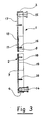
- the heating chamber 1 shown in Figure 1 includes a hot plate 17 composed of an open box 2 of rectangular shape with side walls 3, 4 and walls front 5 and rear 6 secured to a closure plane 7 (see FIG. 3).
- This open box 2 can be made, by folding and welding, from a sheet of steel sheet with a thickness of the order of 4 millimeters.
- Another thin steel sheet 8, of the order of 1.5 millimeters, the front 9 and rear 10 edges were bent forty five degrees down so as to form a front chamber 12 and a rear chamber 13, is welded around its periphery inside the open box 2.
- This sheet steel thin 8 is then connected to the lower part 11 of the plane of closure 7 by spot welding in a staggered configuration in such a way that the welding points 19 are spaced from each other a sufficient distance, of the order of twenty eight to thirty millimeters, in diagonal.
- the front chamber 12 is equipped, by welding, with a connector 14 and the rear chamber 13 is, for its part, also equipped by welding, of a fitting 15.
- the fitting 15 is then closed and a fluid under high pressure, for example hydraulic oil, is introduced into the front chamber 12 through the connector 14.
- the injection of this fluid under high pressure in the front chamber 12 will deform the sheet of thin steel 8 so that it is arched in the areas not linked to the closure plane 7 so as to form cells 18 communicating with each other.
- the high pressure fluid will then removed from the heating chamber 1 and it can therefore receive a heat fluid such as, for example, saturated water vapor.
- the heating enclosure 1 is further provided with a plurality of fixing points 16, constituted by threaded rods, welded to the location of some of the welding points 19 connecting the steel sheet of thin 8 at the closing plane 7.
- These fixing points 16 are intended to serve as anchors to ensure a perfect connection with a rigid chassis, described in more detail with reference to FIGS. 5 and 6, of so as to allow the flatness of the heating chamber 1 to be adjusted as well as giving the whole an acceptable overall rigidity.
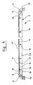
- FIG. 2 is a schematic view showing the flow steam in the heating plate 17 of the heating enclosure 1.
- the saturated steam is injected into front chamber 12 of the plate heating 17 through connection 14.
- Saturated steam is first distributed in the front chamber and will cross, regularly, the plate heating 17 through the alveoli 18 to finally lead in the rear chamber 13 and exit the heating chamber 1 through the fitting 15.
- the vapor flow is therefore divided by the connection points (welding points 19) between the thin steel sheet 8 and the plane closing 7. This will result in a turbulent flow of the flow of steam due to the small passage sections of the cells 18 and This will also increase the transmission of heat to the closing plane 7 which will be in contact with the cardboard corrugated.
- the condensate is pushed at high speed through the hot plate 17 before being collected by condensate collectors, not shown, which can be located in the lower part of the room rear 13.
- the condensate can also be evacuated via the connector 15 which is connected to the steam return circuit.
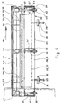
- FIG 3 is a sectional view along III-III of Figure 1 on which we can see the arrangement of the different components of the enclosure heating 1.
- This figure also shows the cells 18 created by the deformation of thin steel sheet 8 where it is not connected to the lower part 11 of the closure plan 7 by the welding points 19.
- a connector 14 for the steam inlet and only one connection 15 for the steam outlet were represented. It is understood that one could imagine that several connections 14 for the entry of steam and that several connections 15 for the steam outlet are connected to their front chamber 12 and rear 13 respectively to improve and regularize the flow of the flow of steam.
- Figure 4 is a side view, in partial section, of Figure 1 representing the configuration of the front 12 and rear 13 chambers obtained by folding the front part 9 and the rear part 10 of the thin steel sheet 8.
- the signs of additional references used in Figures 3 and 4 are the same than those already used in connection with the description of Figure 1 to which we can also refer to.
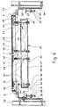
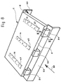
- FIG. 5 is a view in partial section, in length, a heating device representing the heating enclosure 1 equipped a device 20 for adjusting the flatness of the heat exchange surface the heating enclosure 1, this assembly being mounted on a fixed frame 21 between the two side frames 22, 23 (see Figure 6) of the machine manufacture of corrugated cardboard.
- the heating enclosure 1 includes bars 24, 25 for floatingly connecting it to the frame 21. This connection floating is necessary due to the thermal expansion of the enclosure heating 1.
- the frame 21 is formed by two U-shaped irons 26, 27 rendered integral with the side members 32, 33 of the side frames 22, 23 by screws 28 (see figure 6). The height of the frame 21 is adjusted by means of the screws 29 passing through fixing lugs 30 welded against the faces interior of the side frames 22, 23.
- the locking in position of this frame 21 is obtained by means of the locknuts 31 placed on the screws 29.
- the device 20 for adjusting the flatness of the enclosure exchange surface heater 1 consists of a rigid frame 34 made in construction welded. This rigid frame is obtained by assembling U-shaped irons 35, 36, 37 of which only three have been represented here for reasons of simplification of the description. It is understood that one could use a lot more depending on the number of set points chosen to ensure the flatness of the exchange surface. These different U-shaped irons 35, 36, 37 are interconnected by U-shaped irons or possibly flat bars 38, 39.
- the heating enclosure 1 is attached to the rigid frame 34 by tie rods 40 which can be directly screwed to one of their ends on the threaded parts of the fixing points 16 (see figure 3).
- the other end of the tie rods 40 has a threaded portion 41 and is fixed, by means of washers 42, nuts 43 and lock nuts 44, in the wing bottom of the U-shaped iron 35, 36, 37 of the rigid frame 34.
- the flatness of the exchange surface is adjusted by acting on the means of fixing the tie rods 40 to the rigid frame 34. So as to obtain a less punctual adjustment, we imagined placing, on the points of attachment 16, or bars 45 extending over the entire width of the exchange surface, i.e. plates 46 (see Figures 7 and 8) 45, respectively the plates 46, are provided with a wing 47 which engages in the slot 48 of a connecting piece 49 screwed to the end upper of each of the tie rods 40.
- connection between the upper end tie rods 40 and the wing 47 is produced using a pin passing through the connecting piece 49 for engaging in a bore drilled in the piece of connection 49, this bore being of a diameter larger than the diameter of the pin.
- the heating enclosure 1 can also be fixed laterally, so as to take into account thermal expansion phenomena, to frames of the machine by means of the plates 24 and 25 appearing in the figure 7. This method of attachment therefore makes it possible to take account of the constraints thermal expansion so that these do not influence the flatness of the heat exchange surface.
- the heating chamber 1 will thus be laterally floating relative to the rigid frame 34 while being firmly connected to it by the tie rods 40.
- the flatness adjustment will be carried out in the same way as mentioned previously by means of the tie rod fixing members 40 to the frame rigid 34.
- Figure 7 is a view showing the arrangement of organs correction 20 of the flatness of the heating chamber 1. This figure is actually a view from below of the heating enclosure 1 which shows the use of plates 46 in place of the bars 45 shown in FIG. 8. The plates 46 are fixed to the heating enclosure 1 by the fixing points 16.
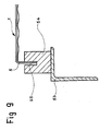
- Figure 8 is a view showing a method of fixing the heating enclosure 1 on a frame 53 connected to the side frames of the corrugated cardboard making machine.
- connection between the heating enclosure 1 and the rigid frame 34 by means of members such as tie rods present between others the advantage of avoiding heat transmission from the enclosure to frame due to the small connection sections and even allows, if need was, the use of insulating bonds so as to further reduce the heat transmissions thus canceling any deformation of the rigid frame 34 which will therefore fully fulfill its solid basic function to regulate the flatness of the exchange surface of the heating enclosure 1.
- the heating enclosure 1 constitutes a very flexible membrane allowing the mechanical adjustment of its exchange surface through a rigid frame which is not dependent on the thermal conditions of the enclosure, in the establishment better heat transmission on the plane of the exchange surface, in improving temperature regulation due to the low thermal inertia of the device, in the use of a small volume of the flux saturated steam, thus eliminating any accumulator or pressure tank and in reducing manufacturing costs in because of the possibility of carrying out a light construction of the device.
Landscapes
- Engineering & Computer Science (AREA)
- Mechanical Engineering (AREA)
- Machines For Manufacturing Corrugated Board In Mechanical Paper-Making Processes (AREA)
- Heat-Exchange Devices With Radiators And Conduit Assemblies (AREA)
Claims (9)
- Heizeinrichtung für eine Maschine zur Herstellung von Wellpappe, insbesondere eine Konvektions-Heizeinrichtung mit einem in einem Konvektor strömenden Heizfluid, umfassend einen Heizkörper (1), in dem gesättigter Dampf strömt, dadurch gekennzeichnet, dass der Körper (1) von einer Heiztafel (17) gebildet ist, welche aus einem rechteckförmigen offenen Kasten (2) mit Seitenwänden (3, 4), einer Vorderwand (5) und einer Rückwand (6) aufgebaut ist, die mit einer Abschlussebene (7) verbunden sind, deren untere Seite (11) mit einem Stahlblech (8) geringer Dicke verbunden ist, welches durch Verformung erhaltene Hohlräume (18) aufweist, wobei der vordere (9) und der hintere Rand (10) des Stahlblechs (8) geringer Dicke um 45° nach unten umgeknickt sind, so dass eine vordere Kammer (12) und eine hintere Kammer (13) gebildet sind, dass dem Körper (1) ein starrer Rahmen (34) zugeordnet ist, mit dem er in thermische Zwänge berücksichtigender Weise durch Einstellorgane verbunden ist, welche zur Vermeidung einer Wärmeübertragung zwischen dem Heizkörper (1) und dem starren Rahmen (34) ausgebildet sind, und dass die von dem Heizkörper (1) und dem starren Rahmen (34) gebildete Anordnung in spielbehafteter Weise in der Maschine zur Wellpappeherstellung befestigt ist, so dass aus der Erwärmung des Heizkörpers (1) resultierenden thermischen Verformungen Rechnung getragen ist.
- Einrichtung gemäss Patentanspruch 1, dadurch gekennzeichnet, dass das Stahlblech (8) geringer Dicke zwischen 0,5 und 1,5 mm an seinem Umfang in den offenen Kasten (2) eingeschweisst ist, dass das Stahlblech (8) geringer Dicke zum anderen - vor Verformung unter der Wirkung eines Hochdruckfluids - mit dem unteren Teil (11) der Abschlussebene (7) durch Schweisspunkte (19) gemäss einer Zickzackanordnung verbunden wird, derart, dass die Schweisspunkte (19) voneinander entfernt sind, dass das Stahlblech (8) geringer Dicke so verformt wird, dass es sich in den nicht mit der Abschlussebene (7) verbundenen Zonen wölbt, so dass sich die miteinander in Verbindung stehenden Hohlräume (18) bilden, und dass die vordere Kammer (12) durch Anschweissen mit einem Anschluss (14) ausgerüstet ist und die hintere Kammer (13) ihrerseits ebenfalls durch Anschweissen mit einem Anschluss (15) ausgerüstet ist.
- Einrichtung gemäss Patentanspruch 2, dadurch gekennzeichnet, dass der offene Kasten (2) durch Knicken und Schweissen aus einem Stahlblechbogen mit einer Dicke im Bereich von 4 mm gebildet ist.
- Einrichtung gemäss Patentanspruch 2, dadurch gekennzeichnet, dass die Schweisspunkte (19) diagonal einen Abstand zwichen 28 und 30 mm voneinander besitzen.
- Einrichtung gemäss Patentanspruch 1, dadurch gekennzeichnet, dass die Heiztafel (17) mit einer Mehrzahl von Befestigungsstellen (16) versehen ist, welche von Innengewindebolzen gebildet sind, die am Ort einiger der das Stahlblech (8) geringer Dicke mit der Abschlussebene (7) verbindenden Schweisspunkte (19) angeschweisst sind, und dass die Befestigungsstellen (16) dazu bestimmt sind, als Verankerungen zur Gewährleistung einer perfekten Verbindung mit dem starren Rahmen (34) zu dienen.
- Einrichtung gemäss Patentanspruch 1, dadurch gekennzeichnet, dass die Verbindungsorgane zwischen dem Heizkörper (1) und dem starren Rahmen (34) von Zugankern (40) gebildet sind, die in einstellbarer Weise am starren Rahmen (34) und in spielbehafteter Weise an dem Heizkörper (1) befestigt sind.
- Einrichtung gemäss Patentanspruch 5, dadurch gekennzeichnet, dass die Befestigungsstellen (16) als Verankerungen für Leisten (45) dienen, welche sich über die gesamte Breite des unteren Teils des Heizkörpers (1) erstrecken.
- Einrichtung gemäss Patentanspruch 7, dadurch gekennzeichnet, dass die Befestigungsstellen (16) als Verankerungen für Plättchen (46) dienen, welche mit gegenseitigem Abstand über die Breite des unteren Teils des Heizkörpers (1) angeordnet sind.
- Einrichtung gemäss Patentanspruch 1, dadurch gekennzeichnet, dass die Verbindung der von dem Heizkörper (1) und dem starren Rahmen (34) gebildeten Anordung mit der Maschine zur Wellpappeherstellung über die Seitenwände (3, 4) des offenen Kastens (2) hergestellt ist, der frei in die Ausfräsungen (55) von Klötzen (54) eingreift.
Applications Claiming Priority (2)
| Application Number | Priority Date | Filing Date | Title |
|---|---|---|---|
| CH3231/95 | 1995-11-15 | ||
| CH323195 | 1995-11-15 |
Publications (2)
| Publication Number | Publication Date |
|---|---|
| EP0774342A1 EP0774342A1 (de) | 1997-05-21 |
| EP0774342B1 true EP0774342B1 (de) | 1999-05-06 |
Family
ID=4251488
Family Applications (1)
| Application Number | Title | Priority Date | Filing Date |
|---|---|---|---|
| EP96118181A Expired - Lifetime EP0774342B1 (de) | 1995-11-15 | 1996-11-13 | Heizvorrichtung für eine Maschine zur Herstellung von Wellpappe |
Country Status (3)
| Country | Link |
|---|---|
| US (1) | US5785118A (de) |
| EP (1) | EP0774342B1 (de) |
| DE (1) | DE69602337T2 (de) |
Families Citing this family (4)
| Publication number | Priority date | Publication date | Assignee | Title |
|---|---|---|---|---|
| US5766409A (en) * | 1996-07-17 | 1998-06-16 | Marquip, Inc. | Apparatus for leveling and supporting the hot plates in a double backer for corrugated paperboard |
| US6759956B2 (en) * | 1998-10-23 | 2004-07-06 | Royal Thoughts, L.L.C. | Bi-directional wireless detection system |
| DE10004754C1 (de) * | 2000-02-03 | 2001-08-02 | Sollich Kg | Kühltunnel für Süßwarenstücke |
| ES2896926T3 (es) | 2019-05-13 | 2022-02-28 | Guangdong Fosber Intelligent Equipment Co Ltd | Placa caliente para máquina corrugadora de cartón de doble cara para la producción de cartón corrugado y máquina corrugadora de cartón de doble cara que comprende una pluralidad de dichas placas |
Family Cites Families (14)
| Publication number | Priority date | Publication date | Assignee | Title |
|---|---|---|---|---|
| US2085191A (en) * | 1935-08-24 | 1937-06-29 | Westinghouse Electric & Mfg Co | Plate condenser |
| DE1088794B (de) * | 1959-03-05 | 1960-09-08 | Waldhof Zellstoff Fab | Trockenvorrichtung fuer Wellpappen-maschinen |
| GB886589A (en) * | 1960-06-17 | 1962-01-10 | Samuel M Langston Co | Method of and apparatus for drying corrugated paper board |
| US3237687A (en) * | 1963-02-08 | 1966-03-01 | Grove Valve & Regulator Co | Heat transfer chamber |
| DE2213745C3 (de) | 1972-03-22 | 1975-02-27 | Werner H.K. Peters, Maschinenfabrik Gmbh, 2000 Hamburg | Heizplatte, insbesondere für Wellpappe-Beklebemaschinen |
| DE2604879A1 (de) * | 1976-02-07 | 1977-08-11 | Gerhard & Rauh | Plattenheiz- bzw. -kuehlkoerper |
| GB1554992A (en) * | 1977-02-10 | 1979-10-31 | Molins Machine Co Inc | Double facer platen |
| US4484623A (en) * | 1983-04-08 | 1984-11-27 | Paul Mueller Company | Dual flow condenser with through connections |
| DE3422684C2 (de) * | 1984-06-19 | 1986-07-24 | Zehnder-Beutler GmbH, 7630 Lahr | Hohlplattenheizkörper |
| US4678027A (en) * | 1984-12-14 | 1987-07-07 | Paul Mueller Company | Dual-walled coiled plate heat exchanger with vented interface |
| US4739825A (en) * | 1986-01-14 | 1988-04-26 | General Electric Company | Apparatus for cooling the core of a liquid cooled transformer |
| US5183525A (en) * | 1990-05-24 | 1993-02-02 | United Container Machinery Group, Inc. | Heater for a double facing corrugating machine |
| GB9012618D0 (en) * | 1990-06-06 | 1990-07-25 | Rolls Royce Plc | Heat exchangers |
| US5501762A (en) * | 1994-06-07 | 1996-03-26 | Marquip, Inc. | Hot plate for corrugated paperboard double facer |
-
1996
- 1996-11-13 DE DE69602337T patent/DE69602337T2/de not_active Expired - Fee Related
- 1996-11-13 EP EP96118181A patent/EP0774342B1/de not_active Expired - Lifetime
- 1996-11-15 US US08/749,631 patent/US5785118A/en not_active Expired - Fee Related
Also Published As
| Publication number | Publication date |
|---|---|
| EP0774342A1 (de) | 1997-05-21 |
| US5785118A (en) | 1998-07-28 |
| DE69602337T2 (de) | 1999-10-14 |
| DE69602337D1 (de) | 1999-06-10 |
Similar Documents
| Publication | Publication Date | Title |
|---|---|---|
| EP0515669B1 (de) | Plattenwärmetauscher | |
| EP0774342B1 (de) | Heizvorrichtung für eine Maschine zur Herstellung von Wellpappe | |
| EP2912396B1 (de) | Wärmetauscher, insbesondere für ein kraftfahrzeug | |
| FR2588614A1 (fr) | Silencieux d'echappement pour turbine a gaz de forte puissance. | |
| FR2787868A1 (fr) | Capteur solaire pour chauffe-eau | |
| FR2557677A1 (fr) | Chaudiere de chauffage a basse temperature, notamment pour les domaines des puissances moyennes et elevees | |
| FR2503836A1 (fr) | Bruleur multiflammes | |
| EP1566591B1 (de) | Heizkessel mit Flammeumkehrung | |
| FR2529995A1 (fr) | Chaudiere d'atre | |
| FR2676269A3 (en) | Perforated-surface gas burner | |
| CH419520A (fr) | Chaudière | |
| FR2850160A1 (fr) | Dispositif de transfert thermique comprenant un module isolant | |
| FR2759447A1 (fr) | Condenseur a reservoir integre pour installation de climatisation, notamment de vehicule automobile | |
| BE562910A (de) | ||
| FR2529648A1 (fr) | Chaudiere a foyer refractaire | |
| FR2523276A1 (fr) | Element de construction pour l'etablissement d'une installation de chauffage et installation de chauffage obtenue | |
| BE390376A (de) | ||
| FR2542073A1 (fr) | Capteur solaire plan a liquide caloporteur | |
| BE395260A (de) | ||
| FR2547026A1 (fr) | Generateur d'eau chaude, notamment chaudiere de chauffage central, a combustible solide, en particulier pour la combustion de buches de bois | |
| BE366960A (de) | ||
| BE428469A (de) | ||
| BE386022A (de) | ||
| BE377640A (de) | ||
| BE386278A (de) |
Legal Events
| Date | Code | Title | Description |
|---|---|---|---|
| PUAI | Public reference made under article 153(3) epc to a published international application that has entered the european phase |
Free format text: ORIGINAL CODE: 0009012 |
|
| 17P | Request for examination filed |
Effective date: 19961113 |
|
| AK | Designated contracting states |
Kind code of ref document: A1 Designated state(s): DE DK GB IT NL |
|
| GRAG | Despatch of communication of intention to grant |
Free format text: ORIGINAL CODE: EPIDOS AGRA |
|
| 17Q | First examination report despatched |
Effective date: 19980707 |
|
| GRAG | Despatch of communication of intention to grant |
Free format text: ORIGINAL CODE: EPIDOS AGRA |
|
| GRAH | Despatch of communication of intention to grant a patent |
Free format text: ORIGINAL CODE: EPIDOS IGRA |
|
| GRAH | Despatch of communication of intention to grant a patent |
Free format text: ORIGINAL CODE: EPIDOS IGRA |
|
| GRAA | (expected) grant |
Free format text: ORIGINAL CODE: 0009210 |
|
| AK | Designated contracting states |
Kind code of ref document: B1 Designated state(s): DE DK GB IT NL |
|
| PG25 | Lapsed in a contracting state [announced via postgrant information from national office to epo] |
Ref country code: NL Free format text: LAPSE BECAUSE OF FAILURE TO SUBMIT A TRANSLATION OF THE DESCRIPTION OR TO PAY THE FEE WITHIN THE PRESCRIBED TIME-LIMIT Effective date: 19990506 |
|
| REF | Corresponds to: |
Ref document number: 69602337 Country of ref document: DE Date of ref document: 19990610 |
|
| GBT | Gb: translation of ep patent filed (gb section 77(6)(a)/1977) |
Effective date: 19990614 |
|
| ITF | It: translation for a ep patent filed | ||
| PG25 | Lapsed in a contracting state [announced via postgrant information from national office to epo] |
Ref country code: DK Free format text: LAPSE BECAUSE OF FAILURE TO SUBMIT A TRANSLATION OF THE DESCRIPTION OR TO PAY THE FEE WITHIN THE PRESCRIBED TIME-LIMIT Effective date: 19990806 |
|
| PLBE | No opposition filed within time limit |
Free format text: ORIGINAL CODE: 0009261 |
|
| STAA | Information on the status of an ep patent application or granted ep patent |
Free format text: STATUS: NO OPPOSITION FILED WITHIN TIME LIMIT |
|
| 26N | No opposition filed | ||
| PGFP | Annual fee paid to national office [announced via postgrant information from national office to epo] |
Ref country code: DE Payment date: 20011015 Year of fee payment: 6 |
|
| PGFP | Annual fee paid to national office [announced via postgrant information from national office to epo] |
Ref country code: GB Payment date: 20011030 Year of fee payment: 6 |
|
| REG | Reference to a national code |
Ref country code: GB Ref legal event code: IF02 |
|
| PG25 | Lapsed in a contracting state [announced via postgrant information from national office to epo] |
Ref country code: GB Free format text: LAPSE BECAUSE OF NON-PAYMENT OF DUE FEES Effective date: 20021113 |
|
| PG25 | Lapsed in a contracting state [announced via postgrant information from national office to epo] |
Ref country code: DE Free format text: LAPSE BECAUSE OF NON-PAYMENT OF DUE FEES Effective date: 20030603 |
|
| GBPC | Gb: european patent ceased through non-payment of renewal fee | ||
| PG25 | Lapsed in a contracting state [announced via postgrant information from national office to epo] |
Ref country code: IT Free format text: LAPSE BECAUSE OF NON-PAYMENT OF DUE FEES Effective date: 20051113 |