EP0773656A2 - Telefonapparat mit Sichtanzeigemodul - Google Patents
Telefonapparat mit Sichtanzeigemodul Download PDFInfo
- Publication number
- EP0773656A2 EP0773656A2 EP96307799A EP96307799A EP0773656A2 EP 0773656 A2 EP0773656 A2 EP 0773656A2 EP 96307799 A EP96307799 A EP 96307799A EP 96307799 A EP96307799 A EP 96307799A EP 0773656 A2 EP0773656 A2 EP 0773656A2
- Authority
- EP
- European Patent Office
- Prior art keywords
- visual display
- display module
- base
- cantilever snap
- molded
- Prior art date
- Legal status (The legal status is an assumption and is not a legal conclusion. Google has not performed a legal analysis and makes no representation as to the accuracy of the status listed.)
- Withdrawn
Links
- 230000000007 visual effect Effects 0.000 title claims abstract description 65
Images



Classifications
-
- H—ELECTRICITY
- H04—ELECTRIC COMMUNICATION TECHNIQUE
- H04M—TELEPHONIC COMMUNICATION
- H04M1/00—Substation equipment, e.g. for use by subscribers
- H04M1/02—Constructional features of telephone sets
- H04M1/0295—Mechanical mounting details of display modules
Definitions
- This invention relates to telephone base modules and, more particularly, to a telephone base including a swivel visual display module.
- Telephone instruments conventionally include a telephone base and a handset which is supported by the base when the telephone is not in use.
- Some more recent telephone devices have included a visual display module that is incorporated into the base.
- the visual display module is used to convey information to a user such as the telephone number of an incoming call, the telephone number of an outgoing call, a directory of telephone numbers or the like.
- the visual display module can be pivotally mounted in the base so that it may be tilted to a desired angular position for ease of reading the displayed information. Arrangements have also been provided to hold the visual display module in the desired tilted angular position. Unfortunately, prior known arrangements for holding the visual display in the desired tilted position have been found to be unduly complex and relatively expensive to implement.
- One particular arrangement employs a pivotally mounted visual display module having an outer convex surface including a plurality of parallel grooves in it.
- Leaf spring members which are physically mounted between upper and lower housings of the base unit are employed to hold the visual display by engaging the grooves therein.
- a problem with using such a leaf spring arrangement is that the leaf springs are expensive and they also require to be physically placed between the upper and lower housings of the base unit. This adds more expense to the overall telephone instrument.
- a swivel visual display module is pivotally mounted and supported by pivot points in both the upper and lower base housings.
- At least one cantilever snap member is molded into one of the base housings, for example, the upper base housing, and is employed to engage indents molded into an outer convex surface of the visual display module to hold the visual display module in several angular positions.
- the at least one cantilever snap member is employed to engage a lower edge of the visual display module and in conjunction with stop members on the visual display module to secure the visual display module in a full upright position.
- the visual display module is secured in its full down position by the at least one cantilever snap member engaging one of the indents which has been strategically placed on the outer convex surface of the visual display module.
- the visual display module is a unitary molded arrangement. Additionally, at least two cantilever snap members are integrally molded into the upper housing of the base unit and a plurality of corresponding indents have been appropriately molded into the outer convex surface of the visual display module. The cantilever snap members in conjunction with the indents allow the securing of the visual display member at individual ones of a plurality of angular positions.
- FIG. 1 is a perspective view of telephone base unit 100 including a visual display module 101 incorporating the invention.
- Such telephone base units are known in the art.
- FIG. 2 is an exploded view of the telephone base unit 100 showing an upper base housing 201 including the visual display module 101 and a lower base housing 202.
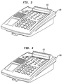
- FIG. 3 is another perspective view of telephone base 100 showing the visual display module 101 in a partially elevated angular position.
- FIG. 4 is still another perspective view of telephone base 100 showing the visual display module 101 in a fully elevated angular position.
- FIG. 5 illustrates a cutaway right side view of visual display module 101 showing the mechanism for indexing the visual display module in a plurality of angular positions.
- the outer convex surface 501 of visual display module 101 includes a plurality of indents 502-1 through 502-n molded therein.
- cantilever snap member 503 which in this example is integrally molded into the upper base housing 201.
- the cantilever snap member is essentially like a spring member that allows the indexing of visual display module 101 via the indents 502 to a plurality of angular positions as desired by a user. It should be noted that since the cantilever snap member 503 is part of the upper housing it does not require any physical placement as the prior art arrangements that used leaf springs or the like.
- FIG. 6 shows a perspective front cutaway view of visual display module 101 illustrating at least two cantilever snap members 503-1 and 503-2. It should be noted that if desired, only one such cantilever snap member may be employed with appropriate indents molded in the convex outer surface of visual display module 101. Alternatively, any number of such cantilever snap members 503 and corresponding indents 502 molded into the convex outer surface of visual display module 101 may be employed. However, in the preferred embodiment only two such cantilever snap members 503-1 and 503-2 are employed.
- FIG. 7 shows a bottom perspective view of visual display module 101 including a stop member 701 and pivot member 702. Note that the visual display module will rotate about the pivot member 702 and when it is in a full upright angular position stop 701 will engage surface 703 to secure it in a full upright position.
- FIG. 8 which is a right side breakaway view of visual display module 101 illustrating the position of the pivot member 702, stop member 701 on surface 703 and one of cantilever snap members 503 engaging the lower edge of the visual display module 101.
- the combination of the stop 701 and the cantilever snap member 503 secures the visual display module in a fully elevated angular position.
- FIG. 9 is a bottom view showing the base upper housing 201 and the bottom of visual display module 101 in its fully elevated position. Again, the visual display module 101 is secured in its position via pivot member 702, stop member 701 and cantilever snap member 503 as shown.
- FIG. 10 is a breakaway perspective view of upper base housing 201 and lower base housing 202 illustrating cantilever snap memebers 503-1 and 503-2 along with pivot members 1001, 1002, 1003 and 1004.
- the cantilever snap members 503 are molded into the upper base housing 201 and therefor eliminate the need for any additional leaf spring members which would have to be physically placed between the upper and lower base housings 201, 202, as in the prior art.
- the visual display module 101 is a unitary molded unit, which also improves any electrostatic discharge from the unit.
- the prior known display units appear to be made of two sections and would require some kind of shielding or other arrangement to minimize such electrostatic discharge.
Landscapes
- Engineering & Computer Science (AREA)
- Signal Processing (AREA)
- Telephone Set Structure (AREA)
- Devices For Indicating Variable Information By Combining Individual Elements (AREA)
Applications Claiming Priority (2)
| Application Number | Priority Date | Filing Date | Title |
|---|---|---|---|
| US55615795A | 1995-11-09 | 1995-11-09 | |
| US556157 | 1995-11-09 |
Publications (2)
| Publication Number | Publication Date |
|---|---|
| EP0773656A2 true EP0773656A2 (de) | 1997-05-14 |
| EP0773656A3 EP0773656A3 (de) | 1999-10-27 |
Family
ID=24220134
Family Applications (1)
| Application Number | Title | Priority Date | Filing Date |
|---|---|---|---|
| EP96307799A Withdrawn EP0773656A3 (de) | 1995-11-09 | 1996-10-29 | Telefonapparat mit Sichtanzeigemodul |
Country Status (5)
| Country | Link |
|---|---|
| US (1) | US6088447A (de) |
| EP (1) | EP0773656A3 (de) |
| JP (1) | JPH09186749A (de) |
| CA (1) | CA2185374C (de) |
| TW (1) | TW307082B (de) |
Families Citing this family (11)
| Publication number | Priority date | Publication date | Assignee | Title |
|---|---|---|---|---|
| DE69826812T2 (de) * | 1997-11-28 | 2005-10-06 | Koninklijke Philips Electronics N.V. | Steckverbindungssystem für Kunststoffschalen |
| USD451486S1 (en) | 2000-07-18 | 2001-12-04 | Iwatsu Electric Co., Ltd. | Telephone |
| USD490393S1 (en) | 2003-03-24 | 2004-05-25 | Nec Infrontia Corporation | Telephone |
| KR100542354B1 (ko) * | 2003-10-13 | 2006-01-10 | 삼성전자주식회사 | 힌지장치가 개선된 전자기기 |
| USD531979S1 (en) * | 2004-09-28 | 2006-11-14 | Avaya Technology Corp. | Telecommunications terminal |
| JP1643920S (de) * | 2019-03-29 | 2019-10-21 | ||
| JP1643977S (de) * | 2019-03-29 | 2019-10-21 | ||
| JP1647047S (de) * | 2019-03-29 | 2019-12-02 | ||
| USD906997S1 (en) * | 2019-10-29 | 2021-01-05 | Panasonic Intellectual Property Management Co., Ltd. | Telephone base unit |
| USD912004S1 (en) * | 2019-10-29 | 2021-03-02 | Panasonic Intellectual Property Management Co., Ltd. | Telephone base unit |
| USD906998S1 (en) * | 2019-12-19 | 2021-01-05 | Panasonic Intellectual Property Management Co., Ltd. | Telephone base unit |
Family Cites Families (4)
| Publication number | Priority date | Publication date | Assignee | Title |
|---|---|---|---|---|
| EP0258717A1 (de) * | 1986-08-20 | 1988-03-09 | Siemens Aktiengesellschaft | Halterung für ein Display |
| US4790504A (en) * | 1987-12-21 | 1988-12-13 | Ncr Corporation | Display support mechanism |
| CA2059860C (en) * | 1992-01-22 | 1996-09-10 | Beverley W. Gumb | Telephone base |
| WO1996029809A1 (en) * | 1995-03-21 | 1996-09-26 | Siemens Rolm Communications Inc. | An interconnection mechanism for a tiltable telephone display unit |
-
1996
- 1996-09-12 CA CA002185374A patent/CA2185374C/en not_active Expired - Fee Related
- 1996-09-14 TW TW085111254A patent/TW307082B/zh active
- 1996-10-29 EP EP96307799A patent/EP0773656A3/de not_active Withdrawn
- 1996-11-08 JP JP8295583A patent/JPH09186749A/ja active Pending
-
1997
- 1997-03-14 US US08/818,083 patent/US6088447A/en not_active Expired - Lifetime
Non-Patent Citations (1)
| Title |
|---|
| None |
Also Published As
| Publication number | Publication date |
|---|---|
| JPH09186749A (ja) | 1997-07-15 |
| TW307082B (de) | 1997-06-01 |
| EP0773656A3 (de) | 1999-10-27 |
| CA2185374C (en) | 2000-01-25 |
| US6088447A (en) | 2000-07-11 |
| CA2185374A1 (en) | 1997-05-10 |
Similar Documents
| Publication | Publication Date | Title |
|---|---|---|
| US5187743A (en) | Telephone base with a display unit | |
| EP0773656A2 (de) | Telefonapparat mit Sichtanzeigemodul | |
| US7110796B2 (en) | Portable terminal device having a display unit utilizing a holographic screen | |
| EP1843559A1 (de) | Tragbares Endgerät mit Schiebebasisstation | |
| US20040266496A1 (en) | Flexible structure, hinge, shutter, mobile communications apparatus and mobile telephone | |
| WO2002054723A1 (en) | A casing | |
| EP0923215A2 (de) | Gelenkmechanismus für ein tragbares Telefon | |
| JPH10501114A (ja) | 傾動可能な電話表示装置用の相互接続機構 | |
| CN104679143A (zh) | 个人计算机 | |
| EP1111976A1 (de) | Schnappanordnung | |
| EP1427173A1 (de) | Klappbares Kommunikationsgerät | |
| CA2427775C (en) | Replaceable personal digital assistant cradle for a telephone | |
| EP1533648B1 (de) | Mobiles Kommunikationsendgerät mit Schutz gegen Aufprall | |
| EP0713314A2 (de) | Handelspult | |
| WO1999021343A1 (en) | Portable telephone with see-through flip element | |
| US6606384B1 (en) | Multimedia communication terminal | |
| EP1356485A1 (de) | Ein gehäuse | |
| JPH06337317A (ja) | 電子回路パッケージの正面板構造 | |
| GB2332925A (en) | Hinge arrangement. | |
| US4448383A (en) | Adjustable telephone message holder | |
| KR100291017B1 (ko) | 탁상형 휴대폰 | |
| CN224109825U (zh) | 平板式电子设备的保护套 | |
| US9185814B2 (en) | Electronic device with rotation mechanism | |
| CN212782500U (zh) | 一种显示模组以及电子设备 | |
| KR100524761B1 (ko) | 휴대용 단말기의 배터리 결합 장치 |
Legal Events
| Date | Code | Title | Description |
|---|---|---|---|
| PUAI | Public reference made under article 153(3) epc to a published international application that has entered the european phase |
Free format text: ORIGINAL CODE: 0009012 |
|
| AK | Designated contracting states |
Kind code of ref document: A2 Designated state(s): DE FR |
|
| PUAL | Search report despatched |
Free format text: ORIGINAL CODE: 0009013 |
|
| AK | Designated contracting states |
Kind code of ref document: A3 Designated state(s): DE FR |
|
| 17P | Request for examination filed |
Effective date: 20000413 |
|
| 17Q | First examination report despatched |
Effective date: 20020924 |
|
| STAA | Information on the status of an ep patent application or granted ep patent |
Free format text: STATUS: THE APPLICATION IS DEEMED TO BE WITHDRAWN |
|
| 18D | Application deemed to be withdrawn |
Effective date: 20030205 |