EP0773608A2 - Flexible board electrical connector - Google Patents
Flexible board electrical connector Download PDFInfo
- Publication number
- EP0773608A2 EP0773608A2 EP96650048A EP96650048A EP0773608A2 EP 0773608 A2 EP0773608 A2 EP 0773608A2 EP 96650048 A EP96650048 A EP 96650048A EP 96650048 A EP96650048 A EP 96650048A EP 0773608 A2 EP0773608 A2 EP 0773608A2
- Authority
- EP
- European Patent Office
- Prior art keywords
- sections
- flexible board
- pressure member
- contact elements
- fulcrum
- Prior art date
- Legal status (The legal status is an assumption and is not a legal conclusion. Google has not performed a legal analysis and makes no representation as to the accuracy of the status listed.)
- Granted
Links
Images


Classifications
-
- H—ELECTRICITY
- H01—ELECTRIC ELEMENTS
- H01R—ELECTRICALLY-CONDUCTIVE CONNECTIONS; STRUCTURAL ASSOCIATIONS OF A PLURALITY OF MUTUALLY-INSULATED ELECTRICAL CONNECTING ELEMENTS; COUPLING DEVICES; CURRENT COLLECTORS
- H01R13/00—Details of coupling devices of the kinds covered by groups H01R12/70 or H01R24/00 - H01R33/00
- H01R13/62—Means for facilitating engagement or disengagement of coupling parts or for holding them in engagement
- H01R13/629—Additional means for facilitating engagement or disengagement of coupling parts, e.g. aligning or guiding means, levers, gas pressure electrical locking indicators, manufacturing tolerances
-
- H—ELECTRICITY
- H01—ELECTRIC ELEMENTS
- H01R—ELECTRICALLY-CONDUCTIVE CONNECTIONS; STRUCTURAL ASSOCIATIONS OF A PLURALITY OF MUTUALLY-INSULATED ELECTRICAL CONNECTING ELEMENTS; COUPLING DEVICES; CURRENT COLLECTORS
- H01R12/00—Structural associations of a plurality of mutually-insulated electrical connecting elements, specially adapted for printed circuits, e.g. printed circuit boards [PCB], flat or ribbon cables, or like generally planar structures, e.g. terminal strips, terminal blocks; Coupling devices specially adapted for printed circuits, flat or ribbon cables, or like generally planar structures; Terminals specially adapted for contact with, or insertion into, printed circuits, flat or ribbon cables, or like generally planar structures
- H01R12/70—Coupling devices
- H01R12/77—Coupling devices for flexible printed circuits, flat or ribbon cables or like structures
- H01R12/79—Coupling devices for flexible printed circuits, flat or ribbon cables or like structures connecting to rigid printed circuits or like structures
-
- H—ELECTRICITY
- H01—ELECTRIC ELEMENTS
- H01R—ELECTRICALLY-CONDUCTIVE CONNECTIONS; STRUCTURAL ASSOCIATIONS OF A PLURALITY OF MUTUALLY-INSULATED ELECTRICAL CONNECTING ELEMENTS; COUPLING DEVICES; CURRENT COLLECTORS
- H01R12/00—Structural associations of a plurality of mutually-insulated electrical connecting elements, specially adapted for printed circuits, e.g. printed circuit boards [PCB], flat or ribbon cables, or like generally planar structures, e.g. terminal strips, terminal blocks; Coupling devices specially adapted for printed circuits, flat or ribbon cables, or like generally planar structures; Terminals specially adapted for contact with, or insertion into, printed circuits, flat or ribbon cables, or like generally planar structures
- H01R12/70—Coupling devices
- H01R12/82—Coupling devices connected with low or zero insertion force
- H01R12/85—Coupling devices connected with low or zero insertion force contact pressure producing means, contacts activated after insertion of printed circuits or like structures
- H01R12/88—Coupling devices connected with low or zero insertion force contact pressure producing means, contacts activated after insertion of printed circuits or like structures acting manually by rotating or pivoting connector housing parts
Definitions
- the present invention relates to electrical connectors for flexible boards.
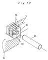
- Japanese patent application Kokai No. 142130/95 discloses an electrical connector of this type as shown in Figs. 11-13.
- the spring contact sections 52A of contact elements 52 are disposed on an opening of a housing 51.
- the housing 51 has circular bearings on the opposite holding sections 53 for supporting a pressure member 54 for rotation (fig. 11) between a closed position where the pressure member 54 is close to the contact elements 52 and an open position where the pressure member 54 is spaced from the closed position.
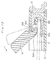
- the contact elements 52 are made by stamping a metal sheet so as to provide a fulcrum section 52B with their center aligned with the center of the circular bearings as shown in Fig. 12.
- the contact elements 52 are disposed in channels 51A of the housing 51 such that the fulcrum sections 52B form a comb-like cylindrical body or shaft between the circular bearings.
- the pressure member 54 has a concave bearing face 54A such that when the pressure member 54 rotates about the circular bearings, the bearing face 54a engages the comb-like shaft for rotation.
- the pressure member 54 has a pressure edge 54B for pressing a flexible board F against the spring contact sections 52A in the opening of the housing 51.
- the housing 51 has receiving faces 51B at a position deeper than the spring contact sections 52A for raising the leading edge of the flexible board F so that when the pressure member 54 is turned downwardly to the closed position, the pressure edge 54B of the pressure member 54 applies a pressure on the flexible board F between the spring contact sections 52A and the receiving faces 51b.
- the pressure member 54 is turned upwardly to the open position as shown by phantom line in Fig. 12, and a flexible board F is put into the opening such that the connection conductors of the board F face down.
- the flexible board F is supported by the spring contact sections 52A and the receiving faces 51B.
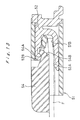
- the pressure member 54 is turned downwardly to the closed position as shown in Fig. 13, so that the pressure edge 54B depresses the flexible board F between the spring contact sections 52A and the receiving faces 52B.
- the connection conditions of the flexible board F are electrically connected under a predetermined pressure to the spring contact sections 52A of the contact elements 52.
- the pressure member 54 When the pressure edge 54B abuts the flexible board F, the pressure member 54 receives a moment of a force and is pushed forwardly (to the left in the figure), but the fulcrum sections 52B engage the concave bearing face 54A to prevent the forward movement of the pressure member 54.
- the operational force upon the pressure member 54 is larger, making the forward moving force larger. If the forward moving force is very large, the bearing face 54A can slip away from the fulcrum sections 52B. Especially, when the number of contact elements 52 is large so that the pressure member 54 is elongated, it is more likely to separate because of a flexure of the pressure member 54 between the circular bearings.
- the spring contact sections are disposed in a zigzag fashion in at least two rows so that the reactive force is split and reduced, requiring lower operational forces. Consequently, the force tending to separate the pressure member from the contact elements is reduced, which in turn reduces the frequency that the pressure member comes off from the contact elements.
- a substantially rectangular elongated housing 1 is made of an insulating material and has an opening which extends in a longitudinal direction at an upper left edge.
- a pair of holding sections extend upwardly at opposite ends of the opening.
- a pair of circular bearings are provided on the holding sections.
- a plurality of retaining channels extend in parallel to and between the holding sections at regular intervals for retaining contact elements 2.
- the contact elements 2 are made by stamping a sheet metal so as to provide a J-shaped finger section 3, a fulcrum section 4 with a semi-circular tip, and a linking section 5 for uniting both the sections 3 and 4.
- a connection section 5A extends outwardly from the linking section 5 such that when the connector is mounted on a circuit board, the connection section 5A is brought into contact with a predetermined conductor of the circuit board.
- a spring contact 3A projects from the finger section 3 toward the fulcrum section 4.
- the contact elements 2 are disposed such that the spring contacts 3A are offset alternately in a zigzag fashion.
- the center 4A of the fulcrum section 4 is aligned with the center of the circular bearings of the housing 1.
- the contact elements 2 are press fitted into the retainer channels from the rear side (right side in the figure) up to a predetermined position where they are retained by projections 5B.
- the retaining channels have receiving faces 1B slightly higher than the finger sections 3 of contact elements 2 for raising the leading edge of a flexible board.
- the elongated pressure member 6 is provided over the opening of the housing 1 for rotation.
- the pressure member 6 has a pressure edge 7 and a pair of studs extending outwardly from opposite ends.
- the studs of the pressure member 6 are supported by the semi-circular bearings of the housing 1 for rotation.
- the pressure member 6 has an arcuate bearing face 8 on the side opposite to the pressure edge 7 so as to engage the fulcrum sections 4 of contact elements 2.
- the fulcrum sections 4 form a comb-like shaft for engaging the bearing face 8 of the pressure member 6. Since the fulcrum sections 4 are made of metal, the comb-like shaft is sufficiently strong to support the pressure member 6.
- the fulcrum sections 4 extend downwardly to such an extent that the center of rotation 4A is protruded to form a deep hook portion 4B while the bearing face 8 extends beyond the center of rotation 4A forming a hook portion 8A. Consequently, when the pressure member 6 turns and the pressure edge 7 abuts the flexible board, the hook portions 4B and 8A of the fulcrum sections 4 and bearing face 8 engage each other.
- the angled pressure edge 7 is made by two planes in this embodiment, but it may be rounded.
- the fulcrum sections 4 may be made separate from the contact elements 2.
- a housing 11 is made of an insulating material and has an opening in the upper left quarter. Like the conventional connector of Fig. 11, the housing 11 has a pair of holding sections on opposite sides of the opening. Arcuate bearings are provided on the holding sections.
- Retention channels are provided in the opening between the holding sections at regular intervals for retaining contact elements.
- the contact elements 12 are made by stamping and forming a conductive or metallic sheet to provide a finger section 13, a fulcrum section 14, a connection section 15A, and a linking section for uniting these sections 13, 14, and 15A.
- the useful conductive materials include metal sheet, metallized sheet, and sheet containing conductive substance.
- the connection section 15A extends outwardly from the linking section 15 to a level substantially equal to the bottom of the housing 11 so that when the housing 11 is mounted on a circuit board, it is brought into contact with the desired conductor on the circuit board for soldering.
- a spring contact portion 13A extends from a tip of the finger section 13 toward the fulcrum section 14.
- the contact elements 12 are disposed such that the spring contact sections 13A are offset alternately in a zigzag fashion. Also, the connection sections 15A are projected alternately from the left and right sides of the housing 11. The center 14A of the fulcrum sections 14 is aligned with the center of the arcuate bearings of the housing 11. The contact elements 12 are press fitted in the retaining channels from alternately the left and right sides of the housing 11 up to a predetermined position where they are retained by projections 15B. Receiving faces 11B are provided in the housing 11 so as to be slightly higher than the finger sections to support the leading edge of a flexible board.
- An elongated pressure member 16 is provided on the opening of the housing 11 for rotation.
- the pressure member 16 has a pressure edge 17 and a pair of studs extending outwardly from its opposite ends. These studs of the pressure member 16 are put in the semi-circular bearings of the housing 11 for rotation.
- An arcuate bearing face 18 is provided on the pressure member 16 on the side opposite to the pressure edge 17 so as to engage the fulcrum sections 14 when the pressure member 16 is attached to the housing 11.
- the fulcrum sections 14 form a comb-like shaft which engages the bearing face 18 of the pressure member 16. Since the fulcrum sections 14 are made of metal, the comb-like shaft is very strong.
- the contact elements 12 are made by stamping a metal sheet and bending its part in a U-shaped form so as to provide a fulcrum section 14B. That is, the fulcrum sections 14 are not made higher than the conventional contact elements but formed within the space between the adjacent contact elements.
- Partition walls 21 are provided on the bearing face 18 of the pressure member 16 at intervals equal to the intervals of the contact elements. Each partition wall 21 consists of a longitudinal wall 21A and a lateral wall 21B. Slits 22 are provided between the adjacent lateral walls 21B.
- Receiving compartments 23 are provided between the adjacent longitudinal walls 21A for accommodating the fulcrum sections 14.
- Arcuate bearing faces 23A are provided on the pressure member 16 from the receiving compartments 23 to the lateral walls 21B. The radius of curvature of the bearing faces 23A is set to be equal to or slightly larger than that of the fulcrum sections 14B.
- the electrical connector is connected to a flexible board as follows:
- the fulcrum sections 14 may be formed as shown in Fig. 7. That is, the fulcrum sections 14 are folded back instead of folded down in Fig. 6.
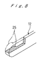
- the fulcrum sections 14 may be made with a stud 25 as shown in Fig. 8.
- the stud 25 may be made by a press machine or bonding a circular sheet.
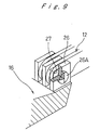
- stud 26A may be provided on the longitudinal walls 26 of the pressure member 16 as shown in Fig. 9. Unlike the bearing faces of Figs. 5 and 7, no lateral wall is required in this embodiment.
- the fulcrum sections 27 have a corresponding aperture.
- the studs 26A may be replaced by a separate pin 28 as shown in Fig. 10.
- the pin 28 is put through the apertures 27 of contact elements 12.
- apertures 30 are provided in longitudinal walls 29 of the pressure member 16 for receiving the pin 28.
- the bearing face of the pressure member engage the fulcrum sections of contact elements so that the pressure member does not come off easily from the fulcrum sections, resulting in the more reliable connector.
- the spring contact sections of contact elements are offset in a zigzag fashion so that the operational force is reduced, thereby further reducing not only the frequency of separation of the pressure member but also the required strength of material.
- the fulcrum sections of contact elements extend downwardly to provide a deep hook portion thereby preventing the pressure member from coming off from the housing without increasing the distance between the contact elements and thus the width of the entire connector.
- the contact elements are able to be made flat, thereby minimizing not only the arranging pitch but also the height of contact elements while preventing separation of the pressure member.
Abstract
Description
- The present invention relates to electrical connectors for flexible boards.
- Japanese patent application Kokai No. 142130/95 discloses an electrical connector of this type as shown in Figs. 11-13. The
spring contact sections 52A ofcontact elements 52 are disposed on an opening of ahousing 51. Thehousing 51 has circular bearings on theopposite holding sections 53 for supporting apressure member 54 for rotation (fig. 11) between a closed position where thepressure member 54 is close to thecontact elements 52 and an open position where thepressure member 54 is spaced from the closed position. Thecontact elements 52 are made by stamping a metal sheet so as to provide afulcrum section 52B with their center aligned with the center of the circular bearings as shown in Fig. 12. Thecontact elements 52 are disposed inchannels 51A of thehousing 51 such that thefulcrum sections 52B form a comb-like cylindrical body or shaft between the circular bearings. Thepressure member 54 has a concave bearingface 54A such that when thepressure member 54 rotates about the circular bearings, the bearing face 54a engages the comb-like shaft for rotation. Thepressure member 54 has apressure edge 54B for pressing a flexible board F against thespring contact sections 52A in the opening of thehousing 51. - As shown in Fig. 12, the
housing 51 has receivingfaces 51B at a position deeper than thespring contact sections 52A for raising the leading edge of the flexible board F so that when thepressure member 54 is turned downwardly to the closed position, thepressure edge 54B of thepressure member 54 applies a pressure on the flexible board F between thespring contact sections 52A and the receiving faces 51b. - In operation, first of all, the
pressure member 54 is turned upwardly to the open position as shown by phantom line in Fig. 12, and a flexible board F is put into the opening such that the connection conductors of the board F face down. At this point, the flexible board F is supported by thespring contact sections 52A and the receivingfaces 51B. Then, thepressure member 54 is turned downwardly to the closed position as shown in Fig. 13, so that thepressure edge 54B depresses the flexible board F between thespring contact sections 52A and the receivingfaces 52B. Thus, the connection conditions of the flexible board F are electrically connected under a predetermined pressure to thespring contact sections 52A of thecontact elements 52. - When the
pressure edge 54B abuts the flexible board F, thepressure member 54 receives a moment of a force and is pushed forwardly (to the left in the figure), but thefulcrum sections 52B engage the concave bearingface 54A to prevent the forward movement of thepressure member 54. - However, if the flexible board F is thicker than the expected, the operational force upon the
pressure member 54 is larger, making the forward moving force larger. If the forward moving force is very large, thebearing face 54A can slip away from thefulcrum sections 52B. Especially, when the number ofcontact elements 52 is large so that thepressure member 54 is elongated, it is more likely to separate because of a flexure of thepressure member 54 between the circular bearings. - Accordingly, it is an object of the invention to provide a flexible board electrical connector having a pressure member resistant to separation from the housing even if the number of contact elements is large and the pressure member is elongated.
- This object is met by the invention claimed in claim 1.
- It is another object of the invention to provide a flexible board electrical connector which is compact.
- This object is met by the invention as claimed in
claim - It is preferred that the spring contact sections are disposed in a zigzag fashion in at least two rows so that the reactive force is split and reduced, requiring lower operational forces. Consequently, the force tending to separate the pressure member from the contact elements is reduced, which in turn reduces the frequency that the pressure member comes off from the contact elements.
- Fig. 1 is a sectional view of an electrical connector according to an embodiment of the invention, wherein a pressure member is at an open position;
- Fig. 2 is a sectional view of the electrical connector of Fig. 1, wherein the pressure member is in motion;
- Fig. 3 is a sectional view of the electrical connector of Fig. 1, wherein the pressure member is at a closed position;
- Fig. 4 is a sectional view of an electrical connector according to a second embodiment of the invention, wherein a pressure member is at an open position;
- Fig. 5 is a sectional view of the electrical connector of Fig. 4, wherein the pressure member is at a closed position;
- Fig. 6 is a perspective view showing the fulcrum sections of contact elements and the bearing faces of the pressure member of Fig. 4;
- Fig. 7 is a perspective view showing a modified fulcrum section of a contact element;
- Fig. 8 is a perspective view showing another modification to the fulcrum section of a contact element;
- Fig. 9 is a perspective view showing still another modification to the fulcrum section and the bearing face of a pressure member;
- Fig. 10 is a perspective view showing yet another modification to the fulcrum section and the bearing sections;
- Fig. 11 is a perspective view, partially in section, of a conventional electrical connector;
- Fig. 12 is a sectional view taken along line XII-XII of Fig. 11; and
- Fig. 13 is a sectional view of the electrical connector of Fig. 11, wherein a pressure member is at a closed position.
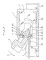
- In Fig. 1, a substantially rectangular elongated housing 1 is made of an insulating material and has an opening which extends in a longitudinal direction at an upper left edge. Like the conventional connector of Fig. 11, a pair of holding sections extend upwardly at opposite ends of the opening. A pair of circular bearings are provided on the holding sections. A plurality of retaining channels extend in parallel to and between the holding sections at regular intervals for retaining
contact elements 2. - The
contact elements 2 are made by stamping a sheet metal so as to provide a J-shaped finger section 3, afulcrum section 4 with a semi-circular tip, and a linkingsection 5 for uniting both thesections connection section 5A extends outwardly from the linkingsection 5 such that when the connector is mounted on a circuit board, theconnection section 5A is brought into contact with a predetermined conductor of the circuit board. Aspring contact 3A projects from thefinger section 3 toward thefulcrum section 4. - It is preferred that the
contact elements 2 are disposed such that thespring contacts 3A are offset alternately in a zigzag fashion. Thecenter 4A of thefulcrum section 4 is aligned with the center of the circular bearings of the housing 1. Thecontact elements 2 are press fitted into the retainer channels from the rear side (right side in the figure) up to a predetermined position where they are retained byprojections 5B. - The retaining channels have receiving
faces 1B slightly higher than thefinger sections 3 ofcontact elements 2 for raising the leading edge of a flexible board. Theelongated pressure member 6 is provided over the opening of the housing 1 for rotation. Thepressure member 6 has apressure edge 7 and a pair of studs extending outwardly from opposite ends. The studs of thepressure member 6 are supported by the semi-circular bearings of the housing 1 for rotation. Thepressure member 6 has an arcuate bearingface 8 on the side opposite to thepressure edge 7 so as to engage thefulcrum sections 4 ofcontact elements 2. When thecontact elements 2 are disposed in the retaining channels of the housing 1, thefulcrum sections 4 form a comb-like shaft for engaging thebearing face 8 of thepressure member 6. Since thefulcrum sections 4 are made of metal, the comb-like shaft is sufficiently strong to support thepressure member 6. - It is noted that the
fulcrum sections 4 extend downwardly to such an extent that the center ofrotation 4A is protruded to form adeep hook portion 4B while thebearing face 8 extends beyond the center ofrotation 4A forming ahook portion 8A. Consequently, when thepressure member 6 turns and thepressure edge 7 abuts the flexible board, thehook portions fulcrum sections 4 and bearingface 8 engage each other. Theangled pressure edge 7 is made by two planes in this embodiment, but it may be rounded. - How to connect a flexible board to the electrical connector will be described below.
- (1) As shown in Fig. 1, the
pressure member 7 is turned upwardly to the open position to expose the opening of the housing 1. A flexible board F is then put into a space between thecontact sections 3A ofcontact elements 2 and thepressure member 6 such that the connection side of the flexible board faces downward. The space is larger than the thickness of the flexible board F so that the board F is put into the space without difficulty, with the leading end raised by thereceiving faces 1B of the housing 1. - (2) Then, as shown in Fig. 2, the
pressure member 6 is turned downwardly so that thepressure edge 7 abuts and depresses the flexible board F which is supported by thespring contact sections 3A of thecontact elements 2 and the receivingfaces 1B of the housing 1. Consequently, the flexible board F is flexed and brought into contact with thecontact sections 3A under pressure. The pressure on the flexible board F by thepressure edge 7 takes the maximum value when thepressure edge 7 reaches a line drawn across thecenter 4A of thefulcrum sections 4 and the adjacentspring contact sections 3A. When thepressure edge 7 depresses the flexible board F, thebearing face 8 abuts thefulcrum sections 4 with a force proportional to the operational moment of a force P. However, thehook portions pressure member 6 does not come off from thefulcrum sections 4. In this embodiment, thespring contact sections 3A ofcontact elements 2 are disposed in a zigzag fashion so that the maximum value of operational pressure is reduced. - (3) When the
pressure member 6 is further turned, thepressure edge 7 enters the housing 1 and passes the maximum value point, and thepressure member 6 is brought to the closed position as shown in Fig. 3. The pressure at this point is less than the maximum value but still sufficiently large to maintain the contact between the flexible board F and thespring contact sections 3A ofcontact elements 2. - (4) Once the flexible board F is connected to the
contact elements 2, even if the flexible board F is pulled so that thepressure member 7 receives a force tending to turn thepressure member 6 to the opening position, thepressure member 6 does not open easily because thepressure edge 7 is located inside with respect to the maximum pressure value position and the reactive force tends to turn thepressure member 6 to the closed position. Thus, the connection between the flexible board F and thecontact elements 2 is maintained unless a force larger than the maximum pressure is applied to thepressure member 6. - Alternatively, the
fulcrum sections 4 may be made separate from thecontact elements 2. - In Fig. 4, a
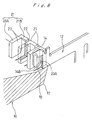
housing 11 is made of an insulating material and has an opening in the upper left quarter. Like the conventional connector of Fig. 11, thehousing 11 has a pair of holding sections on opposite sides of the opening. Arcuate bearings are provided on the holding sections. - Retention channels are provided in the opening between the holding sections at regular intervals for retaining contact elements.
- The
contact elements 12 are made by stamping and forming a conductive or metallic sheet to provide afinger section 13, afulcrum section 14, aconnection section 15A, and a linking section for uniting thesesections connection section 15A extends outwardly from the linkingsection 15 to a level substantially equal to the bottom of thehousing 11 so that when thehousing 11 is mounted on a circuit board, it is brought into contact with the desired conductor on the circuit board for soldering. Aspring contact portion 13A extends from a tip of thefinger section 13 toward thefulcrum section 14. - The
contact elements 12 are disposed such that thespring contact sections 13A are offset alternately in a zigzag fashion. Also, theconnection sections 15A are projected alternately from the left and right sides of thehousing 11. Thecenter 14A of thefulcrum sections 14 is aligned with the center of the arcuate bearings of thehousing 11. Thecontact elements 12 are press fitted in the retaining channels from alternately the left and right sides of thehousing 11 up to a predetermined position where they are retained byprojections 15B. Receiving faces 11B are provided in thehousing 11 so as to be slightly higher than the finger sections to support the leading edge of a flexible board. - An
elongated pressure member 16 is provided on the opening of thehousing 11 for rotation. Thepressure member 16 has apressure edge 17 and a pair of studs extending outwardly from its opposite ends. These studs of thepressure member 16 are put in the semi-circular bearings of thehousing 11 for rotation. An arcuate bearing face 18 is provided on thepressure member 16 on the side opposite to thepressure edge 17 so as to engage thefulcrum sections 14 when thepressure member 16 is attached to thehousing 11. When thecontact elements 12 are put in the retaining channels of thehousing 11, thefulcrum sections 14 form a comb-like shaft which engages the bearingface 18 of thepressure member 16. Since thefulcrum sections 14 are made of metal, the comb-like shaft is very strong. - As shown in Fig. 6, the
contact elements 12 are made by stamping a metal sheet and bending its part in a U-shaped form so as to provide afulcrum section 14B. That is, thefulcrum sections 14 are not made higher than the conventional contact elements but formed within the space between the adjacent contact elements.Partition walls 21 are provided on the bearingface 18 of thepressure member 16 at intervals equal to the intervals of the contact elements. Eachpartition wall 21 consists of alongitudinal wall 21A and alateral wall 21B.Slits 22 are provided between the adjacentlateral walls 21B. Receiving compartments 23 are provided between the adjacentlongitudinal walls 21A for accommodating thefulcrum sections 14. Arcuate bearing faces 23A are provided on thepressure member 16 from the receivingcompartments 23 to thelateral walls 21B. The radius of curvature of the bearing faces 23A is set to be equal to or slightly larger than that of thefulcrum sections 14B. - The electrical connector is connected to a flexible board as follows:
- (1) As shown in Fig. 4, the
pressure member 17 is turned upwardly to open thehousing 11, and a flexible board F is put into a space between thepressure member 16 and thecontact sections 13A ofcontact elements 12 such that the connection section of the flexible board F faces downward. Under this condition, the space is so large with respect to the thickness of the flexible board F that it is easy to put the flexible board F in the space, with the leading end raised by the receiving faces 11B of thehousing 11. - (2) Then, as shown by phantom line in Fig. 4, the
pressure member 16 is turned downwardly to the closed position in Fig. 5 so that thepressure edge 17 abuts and depresses the flexible board F which is supported by thespring contact sections 13A ofcontact elements 12 and the receiving faces 11B of thehousing 11. Consequently, the flexible board F flexes and contacts thecontact sections 13A under pressure. The pressure on the flexible board F by thepressure edge 17 takes the maximum value when thepressure edge 17 reaches a line drawn across thecenter 14A of thefulcrum sections 14 and the adjacentspring contact sections 13A. When thepressure edge 17 depresses the flexible board F, the bearingface 18 pushes thefulcrum sections 14 with a force responsive to an operational moment of a force P tending to come off from thefulcrum sections 14. However, thelateral walls 21B of thepressure member 16 engage thefulcrum sections 14 so as to prevent thepressure member 16 from being deformed and coming off from thefulcrum sections 14. - (3) Once the flexible board F is connected to the
contact elements 12, even if a pulling force is applied to the flexible board F to turn thepressure member 16 to the open position, thepressure member 16 does not open readily because the reactive force from the flexible board F produces a moment tending to close thepressure member 16. Thus, the connection between the flexible board F and thecontact elements 2 is maintained unless a force greater than the maximum value is applied to thepressure member 16. - Alternatively, the
fulcrum sections 14 may be formed as shown in Fig. 7. That is, thefulcrum sections 14 are folded back instead of folded down in Fig. 6. - The
fulcrum sections 14 may be made with astud 25 as shown in Fig. 8. Thestud 25 may be made by a press machine or bonding a circular sheet. - Conversely,
stud 26A may be provided on thelongitudinal walls 26 of thepressure member 16 as shown in Fig. 9. Unlike the bearing faces of Figs. 5 and 7, no lateral wall is required in this embodiment. Thefulcrum sections 27 have a corresponding aperture. - The
studs 26A may be replaced by aseparate pin 28 as shown in Fig. 10. Thepin 28 is put through theapertures 27 ofcontact elements 12. Also,apertures 30 are provided inlongitudinal walls 29 of thepressure member 16 for receiving thepin 28. - As described above, according to an aspect of the invention, the bearing face of the pressure member engage the fulcrum sections of contact elements so that the pressure member does not come off easily from the fulcrum sections, resulting in the more reliable connector. The spring contact sections of contact elements are offset in a zigzag fashion so that the operational force is reduced, thereby further reducing not only the frequency of separation of the pressure member but also the required strength of material.
- According to another aspect of the invention, the fulcrum sections of contact elements extend downwardly to provide a deep hook portion thereby preventing the pressure member from coming off from the housing without increasing the distance between the contact elements and thus the width of the entire connector. Where studs are provided on the pressure member, the contact elements are able to be made flat, thereby minimizing not only the arranging pitch but also the height of contact elements while preventing separation of the pressure member.
Claims (9)
- A flexible board electrical connector, comprising:an insulating housing having an opening and a pair of holding sections;a plurality of contact elements having fulcrum sections and spring contact sections disposed in said opening;a pressure member attached to said housing for rotation between a closed position where it is close to said contact elements and an open position where it is spaced apart from said closed position;said insulating housing having receiving means for supporting a leading portion of a flexible board;said pressure member having a pressure edge and bearing means such that when said pressure member is turned to said closed position, said pressure edge depresses said flexible board against said contact elements while said bearing means engage said fulcrum sections of said contact elements thereby preventing separation between said pressure member and said contact elements.
- A flexible board electrical connector according to claim 1, wherein said receiving means is located at a position deeper than that of said spring contact sections for supporting said leading portion of said flexible board toward said pressure member.
- A flexible board electrical connector according to claim 2, wherein said spring contact sections are disposed in a zigzag fashion at least two rows.
- A flexible board electrical connector according to claim 1, wherein:said contact elements are made of a substantially flat conductive sheet so as to provide fulcrum sections having arcuate tips with their axes extending in a direction of thickness of said conductive sheet;said fulcrum sections project in said direction of thickness; andsaid pressure member has compartments for accommodating said fulcrum sections and said bearing means.
- A flexible board electrical connector according to claim 4, wherein said fulcrum sections have a U-shaped cross section and a circular tip.
- A flexible board electrical connector according to claim 4, wherein said fulcrum sections have cylindrical studs extending in said direction of thickness.
- A flexible board electrical connector according to claim 1, wherein:said contact elements are made of a substantially flat conductive sheet material;each fulcrum section has a circular tip with its axis extending in a direction of thickness of said conductive sheet;said fulcrum sections have apertures provided in said contact elements which are substantially flat;compartment means are provided on said pressure member for accommodating said fulcrum sections and said bearing means; andan attaching pin is provided through said apertures to attach said pressure member to said contact elements.
- A flexible board electrical connector according to claim 7, wherein said bearing means consists of a plurality of cylindrical studs provided on said compartment means.
- A flexible board electrical connector according to claim 7, wherein said bearing means is a common pin provided through said apertures of said contact elements.
Priority Applications (2)
| Application Number | Priority Date | Filing Date | Title |
|---|---|---|---|
| EP00114409A EP1058350B1 (en) | 1995-11-09 | 1996-10-31 | Flexible board electrical connector |
| EP00114408A EP1043806B1 (en) | 1995-11-09 | 1996-10-31 | Flexible board electrical connector |
Applications Claiming Priority (6)
| Application Number | Priority Date | Filing Date | Title |
|---|---|---|---|
| JP07314878A JP3098944B2 (en) | 1995-11-09 | 1995-11-09 | Electrical connector for flexible board |
| JP31487895 | 1995-11-09 | ||
| JP314878/95 | 1995-11-09 | ||
| JP8111128A JP3064232B2 (en) | 1996-04-09 | 1996-04-09 | Electrical connector for flexible board |
| JP111128/96 | 1996-04-09 | ||
| JP11112896 | 1996-04-09 |
Related Child Applications (2)
| Application Number | Title | Priority Date | Filing Date |
|---|---|---|---|
| EP00114408A Division EP1043806B1 (en) | 1995-11-09 | 1996-10-31 | Flexible board electrical connector |
| EP00114409A Division EP1058350B1 (en) | 1995-11-09 | 1996-10-31 | Flexible board electrical connector |
Publications (3)
| Publication Number | Publication Date |
|---|---|
| EP0773608A2 true EP0773608A2 (en) | 1997-05-14 |
| EP0773608A3 EP0773608A3 (en) | 1998-05-13 |
| EP0773608B1 EP0773608B1 (en) | 2002-09-18 |
Family
ID=26450596
Family Applications (3)
| Application Number | Title | Priority Date | Filing Date |
|---|---|---|---|
| EP00114409A Expired - Lifetime EP1058350B1 (en) | 1995-11-09 | 1996-10-31 | Flexible board electrical connector |
| EP00114408A Expired - Lifetime EP1043806B1 (en) | 1995-11-09 | 1996-10-31 | Flexible board electrical connector |
| EP96650048A Expired - Lifetime EP0773608B1 (en) | 1995-11-09 | 1996-10-31 | Flexible board electrical connector |
Family Applications Before (2)
| Application Number | Title | Priority Date | Filing Date |
|---|---|---|---|
| EP00114409A Expired - Lifetime EP1058350B1 (en) | 1995-11-09 | 1996-10-31 | Flexible board electrical connector |
| EP00114408A Expired - Lifetime EP1043806B1 (en) | 1995-11-09 | 1996-10-31 | Flexible board electrical connector |
Country Status (5)
| Country | Link |
|---|---|
| US (2) | US5785549A (en) |
| EP (3) | EP1058350B1 (en) |
| KR (1) | KR100220657B1 (en) |
| DE (3) | DE69623724T2 (en) |
| TW (1) | TW325602B (en) |
Cited By (10)
| Publication number | Priority date | Publication date | Assignee | Title |
|---|---|---|---|---|
| EP0895320A2 (en) * | 1997-07-29 | 1999-02-03 | Hirose Electric Co., Ltd. | Flexible board electrical connector |
| EP0896388A2 (en) * | 1997-08-06 | 1999-02-10 | Robert Bosch Gmbh | Electrical connector |
| EP0926778A2 (en) * | 1997-12-24 | 1999-06-30 | Japan Solderless Terminal Mfg Co Ltd | Connectors for printed circuit boards |
| EP0966070A1 (en) * | 1998-06-19 | 1999-12-22 | Molex Incorporated | Electrical connector for a flat circuit |
| EP1244180A2 (en) * | 2001-03-23 | 2002-09-25 | Hirose Electric Co., Ltd. | Electrical connector for flat cable and its manufacturing method |
| EP1244179A2 (en) * | 2001-03-23 | 2002-09-25 | Hirose Electric Co., Ltd. | Electrical connector for a flat cable |
| EP1311028A2 (en) * | 2001-11-13 | 2003-05-14 | Molex Incorporated | Connector for flat flexible cable |
| EP1566861A1 (en) * | 2002-11-26 | 2005-08-24 | FCI Asia Technology Pte Ltd. | Electrical connector for flexible flat cable |
| US9312631B2 (en) | 2011-12-22 | 2016-04-12 | Phoenix Contact Gmbh & Co. Kg | Electrical connector |
| DE102011122941B3 (en) | 2011-12-22 | 2019-10-10 | Phoenix Contact Gmbh & Co. Kg | Electrical connector and use of the electrical connector |
Families Citing this family (48)
| Publication number | Priority date | Publication date | Assignee | Title |
|---|---|---|---|---|
| US6447305B1 (en) * | 1996-05-14 | 2002-09-10 | Miraco, Inc. | Circuit to printed circuit board stored energy connector |
| JP3005497B2 (en) * | 1997-05-29 | 2000-01-31 | 東北日本電気株式会社 | Flexible board connector |
| JP3430398B2 (en) * | 1998-07-31 | 2003-07-28 | 日本航空電子工業株式会社 | Cable connector |
| TW450458U (en) * | 1999-01-29 | 2001-08-11 | Delta Electronics Inc | Connector |
| JP3320378B2 (en) * | 1999-03-24 | 2002-09-03 | タイコエレクトロニクスアンプ株式会社 | Electrical connector |
| JP4159178B2 (en) * | 1999-04-30 | 2008-10-01 | 日本圧着端子製造株式会社 | Flexible board connector |
| US6332801B1 (en) * | 1999-09-01 | 2001-12-25 | Hirose Electric Co., Ltd. | Insulation replacement electrical connector |
| JP3964583B2 (en) * | 1999-10-26 | 2007-08-22 | 日本圧着端子製造株式会社 | Flexible board connector |
| US6203345B1 (en) * | 1999-11-09 | 2001-03-20 | Hon Hai Precision Ind. Co., Ltd. | Flexible circuit connector |
| JP2001176588A (en) * | 1999-12-17 | 2001-06-29 | Fci Japan Kk | Connector for flat cable |
| JP2001210406A (en) * | 2000-01-25 | 2001-08-03 | Fujitsu Takamisawa Component Ltd | Connector device |
| TW458432U (en) * | 2000-01-28 | 2001-10-01 | Hon Hai Prec Ind Co Ltd | Electrical connector |
| TW443641U (en) * | 2000-02-02 | 2001-06-23 | Hon Hai Prec Ind Co Ltd | Electrical connector |
| JP3754869B2 (en) * | 2000-04-17 | 2006-03-15 | ヒロセ電機株式会社 | Electrical connector for flexible board |
| JP3446136B2 (en) | 2000-06-05 | 2003-09-16 | モレックス インコーポレーテッド | Electrical connector |
| US6379177B1 (en) * | 2000-11-03 | 2002-04-30 | Hon Hai Precision Ind. Co., Ltd. | Flexible printed circuit connector with reliable latching mechanism |
| JP3472559B2 (en) * | 2001-02-22 | 2003-12-02 | 日本圧着端子製造株式会社 | Electrical connector |
| JP2002252049A (en) * | 2001-02-22 | 2002-09-06 | Jst Mfg Co Ltd | Electric connector |
| JP3607878B2 (en) * | 2001-04-25 | 2005-01-05 | 日本圧着端子製造株式会社 | Flexible board connector |
| JP4789362B2 (en) * | 2001-07-25 | 2011-10-12 | 富士機械製造株式会社 | Substrate holding device |
| JP3936596B2 (en) * | 2002-02-04 | 2007-06-27 | 矢崎総業株式会社 | Board connector |
| US7336139B2 (en) * | 2002-03-18 | 2008-02-26 | Applied Micro Circuits Corporation | Flexible interconnect cable with grounded coplanar waveguide |
| US8847696B2 (en) * | 2002-03-18 | 2014-09-30 | Qualcomm Incorporated | Flexible interconnect cable having signal trace pairs and ground layer pairs disposed on opposite sides of a flexible dielectric |
| JP3732157B2 (en) * | 2002-06-14 | 2006-01-05 | 日本航空電子工業株式会社 | Flexible board connector |
| JP3853262B2 (en) * | 2002-07-01 | 2006-12-06 | ヒロセ電機株式会社 | Flat conductor electrical connector |
| DE10249683B4 (en) * | 2002-10-25 | 2006-10-05 | Küster Automotive Door Systems GmbH | Contact terminal for the electr. Contacting a mating contact, esp. For use in electrical motor vehicle components, such as. Window lift systems o. The like. |
| JP3884721B2 (en) * | 2003-04-03 | 2007-02-21 | 日本圧着端子製造株式会社 | Electrical connector |
| TW582631U (en) * | 2003-06-27 | 2004-04-01 | Hon Hai Prec Ind Co Ltd | Electrical connector |
| US20060021764A1 (en) * | 2004-07-29 | 2006-02-02 | Oshkosh Truck Corporation | Piercing tool |
| JP4498948B2 (en) * | 2005-02-24 | 2010-07-07 | ホシデン株式会社 | Flexible board connector |
| US7658630B2 (en) * | 2005-04-18 | 2010-02-09 | Hewlett-Packard Development Company, L.P. | System and method for connecting electronic components |
| US7121874B1 (en) | 2005-09-26 | 2006-10-17 | Myoungsoo Jeon | Flexible printed circuit (FPC) edge connector |
| US7097482B1 (en) * | 2005-10-06 | 2006-08-29 | Hon Hai Precision Ind. Co., Ltd. | Electrical connector with pivot portion |
| JP2007227302A (en) * | 2006-02-27 | 2007-09-06 | Hirose Electric Co Ltd | Electric connector for flat circuit board |
| US20110043236A1 (en) * | 2006-05-31 | 2011-02-24 | Innovative Polymers PTE. Ltd | Compression connector module for use with storage devices and a test carrier incorporating same |
| SG152103A1 (en) * | 2007-11-07 | 2009-05-29 | 3M Innovative Properties Co | Connector |
| SG152104A1 (en) * | 2007-11-07 | 2009-05-29 | 3M Innovative Properties Co | Connector |
| JP4435256B1 (en) * | 2008-11-11 | 2010-03-17 | 株式会社竹内技術研究所 | Flat conductor connector and manufacturing method thereof |
| CN102055093A (en) * | 2009-11-07 | 2011-05-11 | 昆山玉鼎精密模具股份有限公司 | Electric connector |
| JP4931261B2 (en) * | 2010-02-03 | 2012-05-16 | ヒロセ電機株式会社 | Circuit board electrical connector |
| WO2012010964A1 (en) * | 2010-07-19 | 2012-01-26 | Fci | Fpc shielded connector |
| US7931492B1 (en) * | 2010-07-29 | 2011-04-26 | Taiwan Suncagey Industrial Co., Ltd. | Structure of conductive terminal of electrical connector |
| JP5285118B2 (en) * | 2011-05-13 | 2013-09-11 | ヒロセ電機株式会社 | Flat conductor electrical connector |
| JP5621999B2 (en) * | 2012-03-09 | 2014-11-12 | 第一精工株式会社 | Connector device |
| JP6021058B2 (en) * | 2012-08-27 | 2016-11-02 | パナソニックIpマネジメント株式会社 | connector |
| CN103872490B (en) * | 2012-12-12 | 2017-10-03 | 深圳市长盈精密技术股份有限公司 | Electric connector |
| USD757375S1 (en) * | 2014-07-21 | 2016-05-24 | Steve Salais | Dog leash handle |
| USD811382S1 (en) * | 2015-12-29 | 2018-02-27 | Lenovo (Beijing) Co., Ltd. | Multi-mode electronic device with display screen |
Family Cites Families (11)
| Publication number | Priority date | Publication date | Assignee | Title |
|---|---|---|---|---|
| US4334728A (en) * | 1980-05-07 | 1982-06-15 | Amp Incorporated | Zero insertion force connector clip assembly |
| US4367006A (en) * | 1980-12-10 | 1983-01-04 | Amp Incorporated | Connector for flat cable |
| US4718859A (en) * | 1987-03-16 | 1988-01-12 | Molex Incorporated | Zero insertion force connector for flexible flat cable |
| US4778403A (en) * | 1987-07-15 | 1988-10-18 | Elco Corporation | Zero insertion force connector |
| MY104734A (en) * | 1988-05-05 | 1994-05-31 | Whitaker Corp | Zero insertion force electrical connector |
| DE3822980A1 (en) * | 1988-07-07 | 1990-01-11 | Lumberg Karl Gmbh & Co | Connector for the connection of flat electrical conductors |
| JPH0635415Y2 (en) * | 1989-10-06 | 1994-09-14 | connector | |
| DE4141376C2 (en) * | 1991-12-14 | 1993-12-02 | Hirschmann Richard Gmbh Co | Foil connectors |
| TW233382B (en) * | 1993-04-02 | 1994-11-01 | Hirose Electric Co Ltd | |
| JP2814447B2 (en) * | 1994-02-03 | 1998-10-22 | ヒロセ電機株式会社 | Electrical connector for flexible board |
| JP2692055B2 (en) * | 1993-11-18 | 1997-12-17 | ヒロセ電機株式会社 | Electrical connector for flexible board |
-
1996
- 1996-06-18 TW TW085107362A patent/TW325602B/en active
- 1996-07-24 KR KR1019960029954A patent/KR100220657B1/en not_active IP Right Cessation
- 1996-10-31 DE DE69623724T patent/DE69623724T2/en not_active Expired - Fee Related
- 1996-10-31 EP EP00114409A patent/EP1058350B1/en not_active Expired - Lifetime
- 1996-10-31 DE DE69632088T patent/DE69632088T2/en not_active Expired - Fee Related
- 1996-10-31 DE DE69632085T patent/DE69632085T2/en not_active Expired - Fee Related
- 1996-10-31 EP EP00114408A patent/EP1043806B1/en not_active Expired - Lifetime
- 1996-10-31 EP EP96650048A patent/EP0773608B1/en not_active Expired - Lifetime
- 1996-11-05 US US08/740,950 patent/US5785549A/en not_active Expired - Fee Related
-
1998
- 1998-04-20 US US09/062,645 patent/US5904586A/en not_active Expired - Fee Related
Cited By (22)
| Publication number | Priority date | Publication date | Assignee | Title |
|---|---|---|---|---|
| EP0895320A2 (en) * | 1997-07-29 | 1999-02-03 | Hirose Electric Co., Ltd. | Flexible board electrical connector |
| EP0895320A3 (en) * | 1997-07-29 | 2000-03-01 | Hirose Electric Co., Ltd. | Flexible board electrical connector |
| US6116947A (en) * | 1997-07-29 | 2000-09-12 | Hirose Electric Co., Ltd. | Flexible board low profile electrical connector |
| EP0896388A2 (en) * | 1997-08-06 | 1999-02-10 | Robert Bosch Gmbh | Electrical connector |
| EP0896388A3 (en) * | 1997-08-06 | 1999-12-22 | Robert Bosch Gmbh | Electrical connector |
| EP0926778A2 (en) * | 1997-12-24 | 1999-06-30 | Japan Solderless Terminal Mfg Co Ltd | Connectors for printed circuit boards |
| EP0926778A3 (en) * | 1997-12-24 | 2001-05-09 | Japan Solderless Terminal Mfg Co Ltd | Connectors for printed circuit boards |
| EP0966070A1 (en) * | 1998-06-19 | 1999-12-22 | Molex Incorporated | Electrical connector for a flat circuit |
| US6767233B2 (en) | 2001-03-23 | 2004-07-27 | Hirose Electric, Co., Ltd. | Electrical connector for a flat cable |
| EP1244180A2 (en) * | 2001-03-23 | 2002-09-25 | Hirose Electric Co., Ltd. | Electrical connector for flat cable and its manufacturing method |
| US6893288B2 (en) | 2001-03-23 | 2005-05-17 | Hirose Electric Co., Ltd. | Electrical connector for a flat cable |
| EP1244180A3 (en) * | 2001-03-23 | 2003-11-19 | Hirose Electric Co., Ltd. | Electrical connector for flat cable and its manufacturing method |
| EP1244179A3 (en) * | 2001-03-23 | 2003-12-03 | Hirose Electric Co., Ltd. | Electrical connector for a flat cable |
| EP1244179A2 (en) * | 2001-03-23 | 2002-09-25 | Hirose Electric Co., Ltd. | Electrical connector for a flat cable |
| US6711816B2 (en) | 2001-03-23 | 2004-03-30 | Hirose Electric Co., Ltd. | Method of manufacturing electrical connector for flat cable |
| EP1311028A3 (en) * | 2001-11-13 | 2004-02-04 | Molex Incorporated | Connector for flat flexible cable |
| EP1311028A2 (en) * | 2001-11-13 | 2003-05-14 | Molex Incorporated | Connector for flat flexible cable |
| EP1566861A1 (en) * | 2002-11-26 | 2005-08-24 | FCI Asia Technology Pte Ltd. | Electrical connector for flexible flat cable |
| EP1566861A4 (en) * | 2002-11-26 | 2007-08-01 | Fci Asia Technology Pte Ltd | Electrical connector for flexible flat cable |
| US9312631B2 (en) | 2011-12-22 | 2016-04-12 | Phoenix Contact Gmbh & Co. Kg | Electrical connector |
| US9520664B2 (en) | 2011-12-22 | 2016-12-13 | Phoenix Contact Gmbh & Co. Kg | Electrical connector |
| DE102011122941B3 (en) | 2011-12-22 | 2019-10-10 | Phoenix Contact Gmbh & Co. Kg | Electrical connector and use of the electrical connector |
Also Published As
| Publication number | Publication date |
|---|---|
| EP0773608A3 (en) | 1998-05-13 |
| DE69623724T2 (en) | 2003-01-30 |
| EP0773608B1 (en) | 2002-09-18 |
| DE69632085D1 (en) | 2004-05-06 |
| EP1043806A3 (en) | 2001-03-14 |
| DE69632085T2 (en) | 2005-03-03 |
| EP1058350A3 (en) | 2001-06-27 |
| EP1058350B1 (en) | 2004-03-31 |
| EP1058350A2 (en) | 2000-12-06 |
| DE69632088T2 (en) | 2005-03-10 |
| US5904586A (en) | 1999-05-18 |
| DE69632088D1 (en) | 2004-05-06 |
| KR100220657B1 (en) | 1999-09-15 |
| DE69623724D1 (en) | 2002-10-24 |
| EP1043806B1 (en) | 2004-03-31 |
| US5785549A (en) | 1998-07-28 |
| KR970031105A (en) | 1997-06-26 |
| TW325602B (en) | 1998-01-21 |
| EP1043806A2 (en) | 2000-10-11 |
Similar Documents
| Publication | Publication Date | Title |
|---|---|---|
| US5785549A (en) | Flexible board electrical connector | |
| US4978315A (en) | Multiple-conductor electrical connector and stamped and formed contacts for use therewith | |
| US5580272A (en) | Flexible board electrical connector | |
| US5397247A (en) | Connector construction | |
| EP1244179B1 (en) | Electrical connector for a flat cable | |
| EP0615308A2 (en) | Electric connector terminal | |
| US7217158B2 (en) | Electrical connector | |
| EP1826876A2 (en) | Flat circuit board electrical connector | |
| EP0895320A2 (en) | Flexible board electrical connector | |
| EP0099145B1 (en) | Rib cage terminal | |
| EP0852412A2 (en) | Connector for flat cables | |
| US6299458B1 (en) | Intermediate electrical connector | |
| US20060270270A1 (en) | Connector | |
| US6835077B2 (en) | Card connector having a card engaging locking mechanism | |
| US6997761B2 (en) | Electrical contact element | |
| EP1244180B1 (en) | Electrical connector for flat cable and its manufacturing method | |
| EP0721238A2 (en) | Zero insertion force electrical connector and terminal | |
| US6206732B1 (en) | Electrical connector | |
| US7121861B2 (en) | Electrical card connector | |
| US5782655A (en) | Miniature shunt connector with anti-overstress contact element and method of commoning a pair of adjacent terminal posts | |
| EP0638960A2 (en) | Electrical connector having uniform contact receiving slots | |
| JP3064232B2 (en) | Electrical connector for flexible board | |
| US6116956A (en) | Electrical connector for a power supply | |
| JP2849600B2 (en) | Electrical connector | |
| JP3534053B2 (en) | connector |
Legal Events
| Date | Code | Title | Description |
|---|---|---|---|
| PUAI | Public reference made under article 153(3) epc to a published international application that has entered the european phase |
Free format text: ORIGINAL CODE: 0009012 |
|
| AK | Designated contracting states |
Kind code of ref document: A2 Designated state(s): DE FI FR GB IT NL SE |
|
| PUAL | Search report despatched |
Free format text: ORIGINAL CODE: 0009013 |
|
| AK | Designated contracting states |
Kind code of ref document: A3 Designated state(s): DE FI FR GB IT NL SE |
|
| 17P | Request for examination filed |
Effective date: 19980622 |
|
| 17Q | First examination report despatched |
Effective date: 19980929 |
|
| GRAG | Despatch of communication of intention to grant |
Free format text: ORIGINAL CODE: EPIDOS AGRA |
|
| GRAG | Despatch of communication of intention to grant |
Free format text: ORIGINAL CODE: EPIDOS AGRA |
|
| GRAH | Despatch of communication of intention to grant a patent |
Free format text: ORIGINAL CODE: EPIDOS IGRA |
|
| GRAH | Despatch of communication of intention to grant a patent |
Free format text: ORIGINAL CODE: EPIDOS IGRA |
|
| GRAA | (expected) grant |
Free format text: ORIGINAL CODE: 0009210 |
|
| AK | Designated contracting states |
Kind code of ref document: B1 Designated state(s): DE FI FR GB IT NL SE |
|
| PG25 | Lapsed in a contracting state [announced via postgrant information from national office to epo] |
Ref country code: FI Free format text: LAPSE BECAUSE OF FAILURE TO SUBMIT A TRANSLATION OF THE DESCRIPTION OR TO PAY THE FEE WITHIN THE PRESCRIBED TIME-LIMIT Effective date: 20020918 |
|
| REG | Reference to a national code |
Ref country code: GB Ref legal event code: FG4D |
|
| RIC1 | Information provided on ipc code assigned before grant |
Free format text: 7H 01R 12/16 A |
|
| REF | Corresponds to: |
Ref document number: 69623724 Country of ref document: DE Date of ref document: 20021024 |
|
| ET | Fr: translation filed | ||
| PG25 | Lapsed in a contracting state [announced via postgrant information from national office to epo] |
Ref country code: SE Free format text: LAPSE BECAUSE OF FAILURE TO SUBMIT A TRANSLATION OF THE DESCRIPTION OR TO PAY THE FEE WITHIN THE PRESCRIBED TIME-LIMIT Effective date: 20021218 |
|
| PLBE | No opposition filed within time limit |
Free format text: ORIGINAL CODE: 0009261 |
|
| STAA | Information on the status of an ep patent application or granted ep patent |
Free format text: STATUS: NO OPPOSITION FILED WITHIN TIME LIMIT |
|
| 26N | No opposition filed |
Effective date: 20030619 |
|
| PGFP | Annual fee paid to national office [announced via postgrant information from national office to epo] |
Ref country code: FR Payment date: 20060807 Year of fee payment: 11 |
|
| PGFP | Annual fee paid to national office [announced via postgrant information from national office to epo] |
Ref country code: NL Payment date: 20060831 Year of fee payment: 11 |
|
| PGFP | Annual fee paid to national office [announced via postgrant information from national office to epo] |
Ref country code: GB Payment date: 20061025 Year of fee payment: 11 |
|
| PGFP | Annual fee paid to national office [announced via postgrant information from national office to epo] |
Ref country code: IT Payment date: 20061031 Year of fee payment: 11 |
|
| PGFP | Annual fee paid to national office [announced via postgrant information from national office to epo] |
Ref country code: DE Payment date: 20061129 Year of fee payment: 11 |
|
| GBPC | Gb: european patent ceased through non-payment of renewal fee |
Effective date: 20071031 |
|
| NLV4 | Nl: lapsed or anulled due to non-payment of the annual fee |
Effective date: 20080501 |
|
| PG25 | Lapsed in a contracting state [announced via postgrant information from national office to epo] |
Ref country code: DE Free format text: LAPSE BECAUSE OF NON-PAYMENT OF DUE FEES Effective date: 20080501 |
|
| REG | Reference to a national code |
Ref country code: FR Ref legal event code: ST Effective date: 20080630 |
|
| PG25 | Lapsed in a contracting state [announced via postgrant information from national office to epo] |
Ref country code: NL Free format text: LAPSE BECAUSE OF NON-PAYMENT OF DUE FEES Effective date: 20080501 |
|
| PG25 | Lapsed in a contracting state [announced via postgrant information from national office to epo] |
Ref country code: GB Free format text: LAPSE BECAUSE OF NON-PAYMENT OF DUE FEES Effective date: 20071031 |
|
| PG25 | Lapsed in a contracting state [announced via postgrant information from national office to epo] |
Ref country code: FR Free format text: LAPSE BECAUSE OF NON-PAYMENT OF DUE FEES Effective date: 20071031 |
|
| PG25 | Lapsed in a contracting state [announced via postgrant information from national office to epo] |
Ref country code: IT Free format text: LAPSE BECAUSE OF NON-PAYMENT OF DUE FEES Effective date: 20071031 |