EP0773042A2 - Multi-leaf radiation attenuator for radiation therapy with verification system - Google Patents
Multi-leaf radiation attenuator for radiation therapy with verification system Download PDFInfo
- Publication number
- EP0773042A2 EP0773042A2 EP97100108A EP97100108A EP0773042A2 EP 0773042 A2 EP0773042 A2 EP 0773042A2 EP 97100108 A EP97100108 A EP 97100108A EP 97100108 A EP97100108 A EP 97100108A EP 0773042 A2 EP0773042 A2 EP 0773042A2
- Authority
- EP
- European Patent Office
- Prior art keywords
- radiation
- leaf
- patient
- leaves
- fluence
- Prior art date
- Legal status (The legal status is an assumption and is not a legal conclusion. Google has not performed a legal analysis and makes no representation as to the accuracy of the status listed.)
- Granted
Links
- 230000005855 radiation Effects 0.000 title claims abstract description 138
- 238000001959 radiotherapy Methods 0.000 title claims abstract description 27
- 238000012795 verification Methods 0.000 title claims abstract description 18
- 238000010521 absorption reaction Methods 0.000 claims abstract description 30
- 238000002560 therapeutic procedure Methods 0.000 abstract description 19
- 238000012544 monitoring process Methods 0.000 abstract description 2
- 206010028980 Neoplasm Diseases 0.000 description 43
- 238000000034 method Methods 0.000 description 30
- 230000001133 acceleration Effects 0.000 description 15
- 230000008569 process Effects 0.000 description 15
- 238000009826 distribution Methods 0.000 description 10
- 238000003384 imaging method Methods 0.000 description 10
- 230000008901 benefit Effects 0.000 description 8
- 230000000694 effects Effects 0.000 description 7
- 239000000463 material Substances 0.000 description 7
- 230000002829 reductive effect Effects 0.000 description 7
- 238000004364 calculation method Methods 0.000 description 6
- 238000001914 filtration Methods 0.000 description 6
- 238000013519 translation Methods 0.000 description 6
- 230000002238 attenuated effect Effects 0.000 description 5
- 230000001276 controlling effect Effects 0.000 description 5
- 230000000712 assembly Effects 0.000 description 4
- 238000000429 assembly Methods 0.000 description 4
- 238000010586 diagram Methods 0.000 description 4
- 230000006870 function Effects 0.000 description 4
- 238000003860 storage Methods 0.000 description 4
- 230000001186 cumulative effect Effects 0.000 description 3
- 230000005284 excitation Effects 0.000 description 3
- 230000001678 irradiating effect Effects 0.000 description 3
- 230000007246 mechanism Effects 0.000 description 3
- 238000011045 prefiltration Methods 0.000 description 3
- 230000007704 transition Effects 0.000 description 3
- 238000012935 Averaging Methods 0.000 description 2
- 229910052684 Cerium Inorganic materials 0.000 description 2
- 239000000956 alloy Substances 0.000 description 2
- 229910045601 alloy Inorganic materials 0.000 description 2
- GWXLDORMOJMVQZ-UHFFFAOYSA-N cerium Chemical compound [Ce] GWXLDORMOJMVQZ-UHFFFAOYSA-N 0.000 description 2
- 230000008859 change Effects 0.000 description 2
- 238000006243 chemical reaction Methods 0.000 description 2
- 238000002591 computed tomography Methods 0.000 description 2
- 238000004590 computer program Methods 0.000 description 2
- 230000003247 decreasing effect Effects 0.000 description 2
- 230000010354 integration Effects 0.000 description 2
- 230000003993 interaction Effects 0.000 description 2
- 230000001788 irregular Effects 0.000 description 2
- 238000003754 machining Methods 0.000 description 2
- 238000012423 maintenance Methods 0.000 description 2
- 230000007257 malfunction Effects 0.000 description 2
- 230000004044 response Effects 0.000 description 2
- 238000001228 spectrum Methods 0.000 description 2
- 230000007480 spreading Effects 0.000 description 2
- 238000003892 spreading Methods 0.000 description 2
- 229910052715 tantalum Inorganic materials 0.000 description 2
- GUVRBAGPIYLISA-UHFFFAOYSA-N tantalum atom Chemical compound [Ta] GUVRBAGPIYLISA-UHFFFAOYSA-N 0.000 description 2
- WFKWXMTUELFFGS-UHFFFAOYSA-N tungsten Chemical compound [W] WFKWXMTUELFFGS-UHFFFAOYSA-N 0.000 description 2
- 229910052721 tungsten Inorganic materials 0.000 description 2
- 239000010937 tungsten Substances 0.000 description 2
- 238000000342 Monte Carlo simulation Methods 0.000 description 1
- 230000002411 adverse Effects 0.000 description 1
- 230000004888 barrier function Effects 0.000 description 1
- 230000000903 blocking effect Effects 0.000 description 1
- 239000002775 capsule Substances 0.000 description 1
- 239000002131 composite material Substances 0.000 description 1
- 239000000470 constituent Substances 0.000 description 1
- 238000010276 construction Methods 0.000 description 1
- 238000011443 conventional therapy Methods 0.000 description 1
- 230000006378 damage Effects 0.000 description 1
- 230000007812 deficiency Effects 0.000 description 1
- 230000001066 destructive effect Effects 0.000 description 1
- 238000012631 diagnostic technique Methods 0.000 description 1
- 238000004134 energy conservation Methods 0.000 description 1
- 230000003203 everyday effect Effects 0.000 description 1
- 230000004907 flux Effects 0.000 description 1
- 230000003116 impacting effect Effects 0.000 description 1
- 208000015181 infectious disease Diseases 0.000 description 1
- 238000004519 manufacturing process Methods 0.000 description 1
- 238000012986 modification Methods 0.000 description 1
- 230000004048 modification Effects 0.000 description 1
- 230000008450 motivation Effects 0.000 description 1
- 210000000056 organ Anatomy 0.000 description 1
- 230000003094 perturbing effect Effects 0.000 description 1
- 238000012545 processing Methods 0.000 description 1
- 230000000750 progressive effect Effects 0.000 description 1
- 239000012857 radioactive material Substances 0.000 description 1
- 230000001105 regulatory effect Effects 0.000 description 1
- 239000012858 resilient material Substances 0.000 description 1
- 230000002441 reversible effect Effects 0.000 description 1
- 230000009528 severe injury Effects 0.000 description 1
- 238000012546 transfer Methods 0.000 description 1
- 230000009466 transformation Effects 0.000 description 1
Images


Classifications
-
- A—HUMAN NECESSITIES
- A61—MEDICAL OR VETERINARY SCIENCE; HYGIENE
- A61N—ELECTROTHERAPY; MAGNETOTHERAPY; RADIATION THERAPY; ULTRASOUND THERAPY
- A61N5/00—Radiation therapy
- A61N5/10—X-ray therapy; Gamma-ray therapy; Particle-irradiation therapy
- A61N5/1042—X-ray therapy; Gamma-ray therapy; Particle-irradiation therapy with spatial modulation of the radiation beam within the treatment head
-
- A—HUMAN NECESSITIES
- A61—MEDICAL OR VETERINARY SCIENCE; HYGIENE
- A61N—ELECTROTHERAPY; MAGNETOTHERAPY; RADIATION THERAPY; ULTRASOUND THERAPY
- A61N5/00—Radiation therapy
- A61N5/10—X-ray therapy; Gamma-ray therapy; Particle-irradiation therapy
- A61N5/1048—Monitoring, verifying, controlling systems and methods
-
- C—CHEMISTRY; METALLURGY
- C08—ORGANIC MACROMOLECULAR COMPOUNDS; THEIR PREPARATION OR CHEMICAL WORKING-UP; COMPOSITIONS BASED THEREON
- C08F—MACROMOLECULAR COMPOUNDS OBTAINED BY REACTIONS ONLY INVOLVING CARBON-TO-CARBON UNSATURATED BONDS
- C08F234/00—Copolymers of cyclic compounds having no unsaturated aliphatic radicals in a side chain and having one or more carbon-to-carbon double bonds in a heterocyclic ring
- C08F234/02—Copolymers of cyclic compounds having no unsaturated aliphatic radicals in a side chain and having one or more carbon-to-carbon double bonds in a heterocyclic ring in a ring containing oxygen
-
- G—PHYSICS
- G21—NUCLEAR PHYSICS; NUCLEAR ENGINEERING
- G21K—TECHNIQUES FOR HANDLING PARTICLES OR IONISING RADIATION NOT OTHERWISE PROVIDED FOR; IRRADIATION DEVICES; GAMMA RAY OR X-RAY MICROSCOPES
- G21K1/00—Arrangements for handling particles or ionising radiation, e.g. focusing or moderating
- G21K1/02—Arrangements for handling particles or ionising radiation, e.g. focusing or moderating using diaphragms, collimators
- G21K1/04—Arrangements for handling particles or ionising radiation, e.g. focusing or moderating using diaphragms, collimators using variable diaphragms, shutters, choppers
- G21K1/046—Arrangements for handling particles or ionising radiation, e.g. focusing or moderating using diaphragms, collimators using variable diaphragms, shutters, choppers varying the contour of the field, e.g. multileaf collimators
-
- G—PHYSICS
- G21—NUCLEAR PHYSICS; NUCLEAR ENGINEERING
- G21K—TECHNIQUES FOR HANDLING PARTICLES OR IONISING RADIATION NOT OTHERWISE PROVIDED FOR; IRRADIATION DEVICES; GAMMA RAY OR X-RAY MICROSCOPES
- G21K5/00—Irradiation devices
- G21K5/04—Irradiation devices with beam-forming means
-
- G—PHYSICS
- G21—NUCLEAR PHYSICS; NUCLEAR ENGINEERING
- G21K—TECHNIQUES FOR HANDLING PARTICLES OR IONISING RADIATION NOT OTHERWISE PROVIDED FOR; IRRADIATION DEVICES; GAMMA RAY OR X-RAY MICROSCOPES
- G21K5/00—Irradiation devices
- G21K5/10—Irradiation devices with provision for relative movement of beam source and object to be irradiated
Definitions
- This invention relates generally to radiation therapy equipment for the treatment of tumors, or the like, and specifically to a mechanism for regulating the dose of radiation within irregularly shaped zones within a patient and to a mechanism for verifying radiation intensity directed at, and the dose of radiation absorbed within, irregularly shaped zones of a patient.
- Medical equipment for radiation therapy treats tumorous tissue with high energy radiation.
- the dose and the placement of the dose must be accurately controlled to insure both that the tumor receives sufficient radiation to be destroyed, and that damage to surrounding and adjacent non-tumorous tissue is minimized.
- Internal-source radiation therapy places capsules of radioactive material inside the patient in proximity to the tumorous tissue. Dose and placement are accurately controlled by the physical positioning of the isotope.
- internal-source radiation therapy has the disadvantages of any surgically invasive procedure, including discomfort to the patient and risk of infection.
- External-source radiation therapy uses a radiation source that is external to the patient, typically either a radioisotope, such as 60 Co, or a high energy x-ray source, such as a linear accelerator.
- the external source produces a collimated beam directed into the patient to the tumor site.
- External-source radiation therapy avoids some of the problems of internal-source radiation therapy, but it undesirably and necessarily irradiates a significant volume of non-tumorous or healthy tissue in the path of the radiation beam along with the tumorous tissue.
- the adverse effect of irradiation of healthy tissue may be reduced, while maintaining a given dose of radiation in the tumorous tissue, by projecting the external radiation beam into the patient at a variety of "gantry" angles with the beams converging on the tumor site.
- the particular volume elements of healthy tissue, along the path of the radiation beam, change, reducing the total dose to each such element of healthy tissue during the entire treatment.
- the irradiation of healthy tissue also may be reduced by tightly collimating the radiation beam to the general cross section of the tumor taken perpendicular to the axis of the radiation beam.
- Numerous systems exist for producing such a circumferential collimation some of which use multiple sliding shutters which, piecewise, may generate a radio-opaque mask of arbitrary outline.
- the offset of the radiation beam As part of collimating the beam to the outline of the tumor, the offset of the radiation beam, with respect to a radius line between the radiation source and the center of rotation of the radiation source, may be adjusted to allow the treated area to be other than at the center of rotation. Simultaneously changing the offset and the width of the radiation beam as a function of gantry angle allows tumorous tissue having an irregular cross-section within a plane parallel to the radiation beam to be accurately targeted.
- the width and offset of the radiation beam may be controlled by the use of a multiple-leaf circumferential collimator.
- Adjustment of the offset and size of the radiation beam at various gantry angles allows considerable latitude in controlling the dose. Nevertheless, even using these techniques, there is still a considerable amount of undesired dose imparted to healthy tissue, especially where a treatment volume is concave or highly irregular within the plane parallel to the radiation beam.
- a radiotherapy machine providing much reduced irradiation of healthy tissue is presented in U.S. Patent number 5,317,616 issued to Stuart Swerdloff et al, on May 31, 1994.
- the architecture described in the above application employs a radiation source constrained to rotate within a single gantry plane about a patient while intensity of individual rays of the radiation beam are modulated by a set of opaque leaves which move into and out of the radiation beam.
- each slice of the tumor may be controlled to irradiate even tumors having a concave cross section within the gantry plane. This ability to control not just the outline of the radiation but the intensity of each individual ray allows extremely precise control of the irradiation volume.
- An entire tumorous volume may be treated by moving the patient with respect to the gantry plane and irradiating each tumor slice separately.
- the compensator and gantry configuration together substantially increase the ability to conform a radiation dose to an arbitrarily shaped tumor while employing a simplified two-dimensional protocol.
- a single plane configuration provides a number of other benefits. These benefits include the ability to use a single ring gantry to support both a radiation source and a CT system, the advantage of reduced interference between the radiation source and patient (or table) and the advantage of simplified shielding requirements. Furthermore, the simplified architecture enables a therapist to employ a helical scanning method to smoothly irradiate along the length of a tumor so as to avoid irradiation hot spots or irradiation gaps.
- a single plane system must employ a compensator capable of varying the intensity of individual rays of a beam in order to properly treat a tumor.
- the reliability of such a compensator must be extremely high --even a single improperly attenuated beam ray passing through the compensator undetected and irradiating healthy tissue due to a failed compensator component could result in severe damage to healthy tissue.
- Another problem with the compensator described above is that the rays are not uniformly attenuated by the moving leaves because the leaves cannot be moved instantaneously.
- a leaf initially occludes the entire depth of its associated ray within the beam. As the leaf begins to move out of the beam, part of the ray is occluded and another part is left unobstructed. Eventually, the entire ray is unobstructed. The same non-uniform beam attenuation is again encountered when the leaf moves back into the beam.
- This gradation in attenuation can be minimized by equipping the compensator with more powerful actuators to drive the leaves in and out of the fan beam width more rapidly. Bigger actuators, however, are more costly to utilize and maintain. Alternatively thinner leaves may be used which are light weight so that they can be moved more quickly. This, however, demands more actuators, creates more leaf gaps, and must be accommodated by a much more complicated control system.
- the present invention provides a verification system that can be used in conjunction with a radiation intensity compensator to minimize the possibility of an uncontrolled beam ray irradiating non-tumorous tissue.
- the verification system may collect tomographic data on absorbed radiation within the patient and generate tomographic absorption images therefrom. These images may be used for radiation dose verification as well as for planning subsequent therapy sessions.
- the radiation compensator has a radiation source for producing a radiation beam directed toward a patient at a gantry angle, the beam including a plurality of adjacent rays.
- An attenuator disposed between the radiation source and the patient independently controls the fluence of each ray of the beam according to signals indicating desired ray fluences.
- a pre-patient monitor disposed between the attenuating means and the patient, having a plurality of adjacent monitor segments subtended by adjacent rays of the beam produces a measured signal for each monitor segment proportional to the fluence subtending the segment.
- a comparator compares the desired signal to the measured signal to produce a difference value.
- a limiter produces an error signal if the difference value is outside a predetermined error range.
- a first object of the invention is to verify how accurately the intensity of each ray of the beam is being controlled by the compensator. Large discrepancies between the measured and desired signals indicate a malfunction.
- a high signal may also be produced indicating that the measured signal is too high relative to the desired signal yet within the predetermined error range and a low signal may be produced indicating that the measured signal is low relative to the desired signal yet within the predetermined error range.
- the compensator control receiving these signals may adjust the attenuation means to reduce a second ray fluence at a second gantry angle in response to receiving a high signal and to increase a secondary ray fluence at a second gantry angle in response to a low signal.
- Another object of the invention is to provide a system which can compensate for deviations in ray fluence by adjusting ray fluence at later angles.
- the effect of the difference between a desired signal and the measured signal can be reduced as the radiation from the two angles combine.
- the attenuating means is a plurality of radiation attenuating leaves in a support structure positioned generally between the radiation source and the patient.
- the support structure guides the leaves between a closed state within the radiation beam, each leaf thus occluding one ray of the beam, and an open state outside of the radiation beam to allow unobstructed passage of the ray.
- a motivator independently moves each leaf between the open and closed states to effect an open-to-closed desired ratio producing the fluence of each ray.
- the motivator may be a first set of actuators connected by linkages to individual leaves to move the leaves with the movement of the armatures.
- a position sensor determines when each leaf is in the open state and when each leaf is in the closed state and produces an actual ratio of the period of time the leaf is in the open state to the period of time the leaf is in the closed state.
- An error detector generates an error signal by comparing the actual ratio to the desired ratio.
- Another object of the invention is to provide a mechanical compensator system with extremely high reliability.
- the error signal generated by the error detector may be used to indicate a malfunction.
- the supporting structure may guide the leaves between a closed state centered within the radiation beam, the leaf thus occluding one ray of the beam, a first open state with the leaf displaced outside of the radiation beam on a first side of the one ray, and a second open state with the leaf displaced outside of the radiation beam on a second side of the one ray.
- the motivation means moves each leaf alternately between the first open and closed state and between the closed and second open states.
- the plurality of attenuating leaves in the attenuating means above includes a first plurality of radiation attenuating leaves and a second plurality of radiation attenuating leaves and the supporting structure includes a first supporting structure for guiding the first plurality of leaves between a closed state, each leaf thus occluding every other ray of the beam, and an open state outside of the radiation beam and a second support structure for guiding the second plurality of leaves between a closed state, each leaf thus occluding those rays of the beam not occluded by the first plurality of leaves when the latter are in the closed state, and an open state outside of the radiation beam wherein the first plurality of leaves in the closed state are positioned closer to the radiation source than the second plurality of leaves in the closed state.
- the use of two levels increases the spacing between the leaves eliminating their interference yet allows a slight overlap between the leaves of the two levels to eliminate passage of unintended radiation.
- a post-patient monitor may be disposed opposite the pre-patient monitor with respect to the patient and within the fan beam for determining a post-patient fluence of each ray of the beam exiting the patient.
- An absorption calculator compares the pre-patient fluence to the post-patient fluence to produce an absorption value for each ray, the absorption values together providing an absorption profile for the fan beam at a given gantry angle.
- Yet another object of the invention is to provide a record of radiation dose distributed to a tumor site.
- This dose record may be used by a radiotherapist to verify radiation dose throughout the volume of a tumor.
- the dose record reduces the possibility that interruptions in a therapy session will require termination of the session. Sessions can resume where they were interrupted.
- the dose record may be used in planning suitable subsequent therapy sessions.
- a radiation therapy unit 10 suitable for use with the present invention includes a radiation source 12 producing a generally conical radiation beam 14' emanating from a focal spot 18 and directed towards a patient 17 (not shown in Fig. 1).
- the conical beam 14' is collimated by a radiation opaque mask 16 constructed of a set of rectangular collimator blades to form a generally planar fan beam 14 centered about a fan beam plane 20.
- a compensator 22 is centered in the fan beam 14 and about the fan beam plane 20, prior to the radiation being received by the patient 17, and includes a plurality of adjacent trapezoidal leaves 30 which together form an arc of constant radius about the focal spot 18.
- the leaves 30 are held in sleeves 24.
- the sleeves 24 are constructed of radio-translucent materials and attached at their inner ends 23 to a mounting plate 26 which is fixed relative to the focal spot 18.
- the mounting plate 26 is constructed of a sturdy, radiopaque material and is positioned just outside the fan beam 14 to prevent interference with the fan beam 14.
- each sleeve 24 is open at its outer end 27 to receive, by sliding, a comparably sized trapezoidal leaf 30 constructed of a dense, radiopaque material such as lead, tungsten, cerium, tantalum or a related alloy.
- Each leaf 30 may slide completely within its corresponding sleeve 24 to block the ray 28 associated with that sleeve 24.
- the sleeves 24 are of ample length to permit each leaf 30 to slide out of the path of the fan beam 14, so as to leave its corresponding ray 28 completely unobstructed, and yet to still be guided by the sleeve 24. In this non-blocking position, a leaf is referred to as being in the "open state”.
- Each leaf 30 moves rapidly between its open and closed states by means of a primary corresponding relay-like electromagnetic actuator 32 connected to the leaf 30 by a slider member 34.
- the actuators 32 have internal armatures (not shown) received within solenoid electromagnets.
- the armature may be moved at high velocity by means of varying electrical excitations of their associated electromagnets.
- the electrical excitations are provided by a compensator control (not shown in Figs. 1 or 2) to be described below.
- the actuators 32 are capable of applying high forces to the leaves 30 to move them rapidly and independently between the open and closed states.
- Each leaf 30 is also provided with a back up actuator 35 located below its primary actuator 32 on the outer edge of the leaf 30.
- the secondary actuator 35 is employed when the primary actuator 32 fails as will be described in more detail below.
- the leaves 30 are supported and guided within the sleeves 24 by guide rails 36 fitted into notches 38 cut along the edges of the leaves 30.
- the notches 38 allow the guide rails 36 to slidably retain the leaves 30 within the sleeves 24 during motion between the open and closed states.
- each leaf 30 In the closed state, the inner end 40 of each leaf 30 is captured by a rigid collar 42 attached to the mounting plate, which aligns the leaf 30, more accurately than may be done by the guide rails 36, with the mounting plate 26 and hence with the fan beam 14.
- the guide rails 36 which are ideally radio-translucent, are relatively insubstantial
- the collar 42 positioned outside the fan beam 14 on the mounting plate 26, need not be radio-translucent and hence is more substantial in construction.
- a collar (not shown) similar to collar 42, supports each leaf 30 when it is fully in the open state. Because the leaves 30 spend most of their time fully in the open or closed states, they are, at most times, firmly located by a supporting collar 42.
- P 1-(1- P 1 ) n where n is the number of leaves 30. Since the leaves 30 are light, the slide member 34 is under little stress and so it has a low probability P slide of failure.
- a light opaque trigger member 19 is integrally attached to the inner edge 40 of each leaf 30, the trigger member 19 extending laterally outward parallel to the movement axis 25 of each leaf 30.
- the trigger member 19 passes through a trigger bore 31 in the back wall 29 of the mounting plate 26.
- a plurality of light emitting diode 21 and light detector 15 pairs are positioned on the outer surface of the back wall 29, the elements of each pair opposing each other on opposite sides of an associated trigger bore 31.
- its associated trigger member 19 extends through the trigger bore 31 and blocks the light path 33 between the light emitting diode 21 and light detector 15.
- the trigger member 19 does not extend through the trigger bore 31 and hence light passes from the emitting diode 21 to the light detector 15.
- the probability of the light detector 15 failing is P verify .
- An axially compressible spring 39 is provided between the outer edge 41 of each leaf 30 and the front wall (not shown) of the mounting plate 26 to move the leaf 30 to the closed position absent force from its actuator 32.
- a system employing a light detector 15, primary and backup actuators 32, 35 and which are regularly serviced, would have downtime due to failure of a leaf 30 according to the probability equation: P 1 1-(1- P slide )(1- P verify )[1-( P actuator N maint ) 2 ] wherein P actuator is the probability of the actuator or control electronics failing during a year and N maint is the number of maintenance services in the year (e.g. it could be every day). The exponent 2 accounts for the failure of both actuators in the maintenance period. This equation basically says that failure of a leaf 30 will happen if the slider 34 fails, the verification system fails or both of the actuators 32, 35 fail before the system can be serviced.
- a pre-patient multi-segment ion chamber 47 is positioned between the compensator 22 and the patient 17. Each ray 28 of the fan beam 14 subtends a separate monitor segment 49 as it passes through the ion chamber 47.
- a post-patient multi-segment ion chamber 53 is positioned directly opposite the radiation source 12 on the gantry 44 so as to intercept the fan beam 14 as it exits the patient 17.
- the separate monitor segments 54 of the second ion chamber 53 like the monitor segments 49 of the first ion chamber 47, are each subtended by individual rays 28 of the fan beam 14.
- the ion chambers 47, 53 produce signals indicating the fluence of rays 28 (as generally understood in the art) and as used by the computer 51 to determine radiation dose in a manner to be described below.
- the radiation source 12 is mounted on a gantry 44, the latter rotating within the fan beam plane 20 about a center of rotation 45 in the patient 17 so that the fan beam 14 may irradiate a slice of the patient 17 from a variety of gantry angles ⁇ .
- the radiation source 12 is controlled by a radiation control module 48 which turns the radiation beam 14 on or off under the control of a computer 51.
- a compensator control 52 directed by a timer generating desired position signals provides electrical excitation to each electromagnet to control, separately, the actuators 32 to move each of the leaves 30 in and out of its corresponding sleeve 24 and ray 28 (see also Fig. 1).
- the compensator control 52 moves the leaves 30 of the compensator 22 rapidly between their open and closed states to either fully attenuate or provides no attenuation to each ray 28. Gradations in the fluence of each ray, as needed for each fluence profile, are obtained by adjusting the relative duration during which each leaf 30 is in the closed position compared to the relative duration during which each leaf 30 is in the open position, for each gantry angle.
- the ratio between the closed and open states or the "duty cycle" for each leaf 30 affects the total energy passed by a given leaf 30 at each gantry angle and thus controls the average fluence of each ray 28.
- the ability to control the average fluence at each gantry angle permits accurate control of the dose provided by the radiation beam 14 through the irradiated volume of the patient 17 by therapy planning methods to be described below.
- the compensator control 52 also connects with computer 51 to allow program control of the compensator 22 to be described.
- a tomographic imaging system 11 employing an x-ray source 46 and an opposed detector array 50 may be advantageously mounted on the same gantry 44 as the radiation source 12 to produce a tomographic or slice image of the irradiated slice of the patient 17 prior to radiation therapy for planning purposes.
- such tomographic imaging may be performed on a separate machine and the slices aligned according to fiducial points on the patient 17.
- a gantry control module 9 provides the signals necessary to rotate the gantry 44 and hence to change the position of the radiation source 12 and the angle ⁇ of the fan beam 14 for the radiation therapy, as well as for the computed tomography x-ray source 46 and detector array 50 also attached to gantry 44.
- Gantry control module 9 connects with computer 51 so that the gantry may be rotated under computer control and also to provide the computer 51 with a signal indicating the gantry angle ⁇ to assist in that control.
- Control modules for the tomographic imaging system 11 include: x-ray control module 56 for turning on and off the x-ray source 46, and data acquisition system 58 for receiving data from the detector array 50 in order to construct a tomographic image.
- An image reconstructor 60 receives the data from the data acquisition system 58 in order to assist in "reconstructing" a tomographic treatment image from such data according to methods well known in the art.
- the image reconstructor 60 also communicates with computer 51 to assist in high speed computations used in the present invention as will be described below.
- the tomographic treatment image allows verification of the patient setup just prior to radiation therapy treatment.
- An image reconstructor 60 typically comprising a high speed array processor or the like may use the actual fluence signals 57 and barrier signals 59 to produce a tomographic absorption image to be used for verification and future therapy planning purposes as described in more detail below.
- a terminal 62 comprising a keyboard and display unit 63 allows an operator to input programs and data to the computer 51 and to control the radiation therapy and tomographic imaging equipment 10 and 11 and to display tomographic images produced by the image reconstructor 60 on the display 63.
- a mass storage system 64 being either a magnetic disk unit or tape drive, allows the storage of data collected by the tomographic imaging system 11 and the multi-segment ion chambers 47, 53 for later use.
- Computer programs for operating the radiation therapy system 10 will generally be stored in mass storage unit 64 and loaded into the internal memory of the computer 51 for rapid processing during use of the system 10.
- the compensator control 52 receives from the computer 51 a fluence profile for each gantry angle.
- the fluence profile describes the intensity or fluence of each ray 28 of the radiation beam 14 that is desired for that gantry angle ⁇ at a given position of the patient support table (not shown) as translated through the radiation beam 14.
- the collection of fluence profiles over a range of rotation gantry angles is termed a "treatment sinogram".
- the generation of a treatment sinogram needed to obtain the full benefits of the above described compensator is performed by specially developed software running on the computer 51 and reconstructor 60.
- the treatment planning is performed in software, it will be recognized that the planning may also be implemented in discrete electronic circuitry dedicated to this operation and that such dedicated circuitry may be employed to provide even greater speed to this process.
- the generation of the desired treatment sinogram to control compensator 22 begins with the definition of a desired dose map 66.
- a typical desired dose map 66 assigns a relatively high radiation dose, within a dose constraint, to an area of tumorous tissue 68 and a second lower radiation dose to the area of healthy tissue 70 outside of that region.
- the healthy tissue 70 may include an area 72 including a radiation sensitive organ or the like to which an even lower radiation dose may be assigned.
- the desired dose map 66 is stored within the memory of computer 51 as an array of elements each element holding one digital value, and may be most easily entered by displaying the tomographic view of the slice of patient 17 on the display 63 of the terminal 62 and manually tracing around the tumorous area 68 using a track-ball or a similar input device as is well understood in the art. Standard area-filling computer programs may be used to transfer the dose values assigned to each traced region to the appropriate element in the array of memory representing the desired dose map 65.
- Each element of the dose map 66 thus defines the dose desired at each of the plurality of volume elements 74 ("voxels") within a slice of the patient 17.
- each voxel 74 of the patient 17 may be identified by a vector r ⁇ defined from a given reference point 76.
- the dose at each voxel 74 is D( r ⁇ ).
- the dose at any voxel r ⁇ will depend on the energy received at that voxel r ⁇ from radiation scattered from adjacent voxels (where adjacent voxels r ⁇ include the voxel r ⁇ , i.e., the radiation received directly from the radiation source 12).
- ⁇ ⁇ is an effective mass attenuation value at the voxel r ⁇
- E is the energy of the radiation photons in Joules
- ⁇ is the distribution of the fluence rate (flux density).
- Equation (4) basically relates how much energy from the ray 47 interacts with the voxel r'.
- A( r ⁇ - r ⁇ ' ) is a convolution kernel describing non-stochastic energy transport or scattering in a uniform medium.
- A( r ⁇ - r ⁇ ' ) thus describes how the energy from each voxel r ⁇ ' spreads to contribute to the dose at voxel r ⁇ .
- the kernel A( r ⁇ - r ⁇ ' ) may be generated using a Monte Carlo method as is generally understood in the art. As mentioned, it is a three-dimensional function indicating the fraction of energy absorbed at voxel r ⁇ per unit of energy released at voxel r ⁇ ' .
- the kernel would be approximated as a delta function.
- the anisotropy of A( r ⁇ - r ⁇ ' ) is related to the gantry angle ⁇ and thus of the angle of incidence of the ray 28 at r ⁇ ' . If the gantry angles ⁇ at which the patient 17 is irradiated are predetermined, a multi-direction convolution kernel B( r ⁇ - r ⁇ ' ), shown in Fig. 9, may be created from weighted superimposition of the kernels A( r ⁇ - r ⁇ ' ).
- Equation (7) substantially simplifies the calculation of dose from terma but still requires a convolution for each voxel r ⁇ times the total number of voxels r ⁇ ' to calculate the dose over the entire patient volume.
- the kernel B( r ⁇ - r ⁇ ' ) for an external radiation source 12 is a complex function of: (1) beam hardening of a polyenergetic x-ray beam (i.e., the effect of the filtration of the patient 17 in increasing the proportion of high frequency or high energy radiation components), (2) the number of rays 28 crossing each voxel, and (3) exponential attenuation by the patient mass.
- this first factor is neglected because it is an effect smaller than the attenuation problem.
- the photon energy spectrum in the patient 17 may be assumed to be the same as that of the external radiation source 12. This simplification is not required, however, and it will be understood that beam hardening could be accurately accounted for by representing a photon energy spectrum by a finite number of separately convolved energy intervals.
- the second factor the difference in the number and orientation of rays 28 that cross each voxel, caused by the geometry of a finite number of gantry angles and the fan orientation of the beam 14, affect spatial invariance. Problems arising from the fan orientation of the beam (in contrast to a parallel beam geometry) are largely solved if there is a full rotation of the gantry 44. Errors resulting from the fact that irradiation is performed at only a finite number of gantry angles have been determined to be acceptable.
- the third factor affecting the assumption of spatial invariance is the attenuation of the medium. This affects the fractional contribution of the total terma from the beams at each gantry angle. Accordingly, in those steps of the planning procedure, as will be noted below, where accurate calculation of dose is critical, the dose distribution is calculated separately for each beam based on the attenuation of overlying voxels, such attenuation deduced from the parameters of the tomographic image. In this case the simplification of equation (8) may not be employed and repeated convolutions must be performed. In certain steps in the planning process, however, as will be noted, an estimate is sufficient and in these cases B( r ⁇ - r ⁇ ' ) is assumed to be spatially invariant and the dose calculated according to equation (8).
- This inversion requires that there be no significant "zeros" (typically at high frequencies) in the denominator term F ⁇ B( r ⁇ - r ⁇ ' ) ⁇ or more simply that the kernel B( r ⁇ - r ⁇ ' ) be spatially compact (i.e., the Fourier transform of a spatially compact kernel will have significant high frequency content). It has been determined by the present inventors that the kernels dictated for patients 59 are sufficiently compact to allow this Fourier deconvolution.
- this deconvolution to produce a terma map 82 giving the terma for each voxel r ⁇ , from the desired dose map 66, is represented by process block 80.
- ⁇ ⁇ may be estimated and considered a constant or actual m/r may be deduced from the tomographic scan data collected by means of the tomographic imaging system 60, (shown in Fig. 5). In this manner and as illustrated by process block 84 of Fig. 10, a fluence map 86 giving the fluence at each point of the terma map may be determined.
- ⁇ 0 ( ⁇ , ⁇ ) is the energy fluence for a given ray 28 as described by ⁇ ( ⁇ - r ⁇ ⁇ r ⁇ ) at the exit of the compensator 22 and serves to define the fluence profile of the compensator and ⁇ and ⁇ are the gantry angle and the offset angles of the ray 28 as previously described.
- the exponential term represents the attenuation of the ray 28 from the exit of the compensator 22 to the voxel r ⁇ caused by the mass of the patient 17
- ⁇ ⁇ ( r ⁇ ) is the attenuation for each voxel r ⁇ along the ray 28
- ⁇ ( r ⁇ ) is the density of each voxel r ⁇
- SSD( ⁇ , ⁇ ) is the distance between the exit of the compensator 22 and the surface of the patient 17
- r ⁇ is a unit vector along r ⁇ (where the origin is now assumed to be the center of rotation of the gantry 44)
- p is the perpendicular distance from the gantry's center of rotation 45 and the ray 28.
- the vector is simply a vector along the ray 28 to provide an integration variable.
- the fluence at each voxel r ⁇ is related to the fluence of the radiation beam 14 emitted from the compensator 22 by equation (11).
- the density and attenuation of each voxel r ⁇ , ⁇ ⁇ ( r ⁇ ) and ⁇ ( r ⁇ ) are assumed to be constant and the fan beam of radiation is approximated by a parallel beam, hence SSD 2 ( ⁇ , ⁇ )
- 2 1.
- the fluence map 86 may be "reverse" back projected (i.e. projected) by projector 85 to determine a fluence profile to be produced by the external-source necessary to generate the desired fluence map and hence dose.
- Equation (13) The projection of equation (13) is represented by projector 85 in Fig. 10.
- the projection process for the purpose of computing fluence profiles for the compensator 22, differs in a fundamental way from the simple inverse of tomographic back projection. The difference is primarily in a concern for the sharpness in the transition of the dose between the irradiated tumorous tissue 68 and the healthy tissue 70. Sharpness in this transition region reduces the irradiation of healthy tissue 70 and is preferred over actual fidelity of the dose to the desired dose map 66.
- This prefilter 88 serves to increase the high frequency content of the fluence map 86 and thus to aid in rapid transition of dose at the tumor/non-tumor interface.
- this prefilter 88 is similar to the filter used in tomographic imaging's "filtered" back projection. That is, like tomographic imaging, the filter de-emphasizes the low frequency components of the projection in producing image data.
- other prefilters may be applied to correct for the use of the radially symmetric kernel (equation (6)) in computing the dose map from the terma map composed from the fluence profile.
- the generation of a fluence map and the calculation of the fluence profiles need not be performed as discrete steps but may be accomplished by a direct projection of the dose map with appropriate filtering.
- the filtering is accomplished by a "fast inversion filter" which combines in projection space the operation of deconvolution and ramp filtration.
- the fluence profile calculations of block 78 including the deconvolver 80, the fluence calculator 84, the prefilter 88 which includes any projection space filter (such as a ramp filter, a fast inversion filter followed by truncation of zeros), and the projector 85 thus produce fluence profiles which together create an estimated treatment sinogram 87' from the desired dose map 66.
- the fluence profile calculator 78 may use the Fourier convolution of equation (9) in the estimate of the fluence profiles at this stage, accepting minor inaccuracies in that process, to be corrected at a later stage, as will be described below.
- the fluence profile calculator 78 converts the desired dose map 66 to an estimated treatment sinogram 87', however the fluence profiles of this estimated treatment sinogram 87' may not be used to control the compensator 22 because, in general, the estimated treatment sinogram 87' will include positive and negative values of fluence. Only positive values of fluence are physically realizable by the compensator 22; a negative value of fluence would represent a ray 28 that absorbed radiation along its path which is physically unrealizable.
- the fluence values of the estimated treatment sinogram 87' are truncated to positive fluence values 89.
- the estimated treatment sinogram 87' no longer produces the desired dose map.
- the amount of error resulting from the truncation producing the positive fluence profiles 89 is determined by back-projecting the positive fluence values 89 to an actual dose map, 90 deviating from the desired dose map 66.
- This back projection is accomplished by computing a fluence map from the positive fluence values 89 per equation (11) and a terma map per equation (4) and then convolving the terma map with the kernel per equation (7) to establish the actual dose map 90 per process block 92 of Fig. 11.
- the projection of a fluence profile onto a patient 17 to compute a dose map may be performed by a number of other procedures known to those of ordinary skill in the art.
- the actual dose map 90 is compared to the desired dose map 66 to produce residual dose map 96 as indicated by process block 94.
- the comparison subtracts from the values of each voxel r ⁇ of the actual dose map 90, the greater of: a) the corresponding value of desired dose map 66, or b) a predetermined upper dose constraint.
- the predetermined upper dose constraint is a threshold number that is deemed an acceptable dose to tumorous tissue 76.
- the result of this comparison process 94 is to produce a residual dose map 96 shown in Fig 12(a).
- This residual dose map 96 is then, again, operated on by the fluence profile calculator 78 (in lieu of the desired dose map 66) to produce an error fluence profile 98 (in lieu of the estimated treatment sinogram 87).
- a thus produced error fluence profile 98 is subtracted by subtracter 100 from the estimated treatment sinogram 87' to produce a new estimated treatment sinogram 90.
- this new estimated treatment sinogram 87 is repeatedly operated on by process blocks 88, 92, 94 and 78 for a predetermined number of iterations, the magnitude of the error fluence profile 98 values decreasing with each iteration as shown in Figs. 12(b)-(c) until a suitably low error fluence profile 98 is obtained.
- the new estimated fluence profile 87 is then truncated per process block 88 to produce a final sinogram 91 for use in controlling the compensator 22, as previously described.
- dose maps obtained by the present invention corresponding to a desired dose map 66 of Fig. 6(a) are shown after: one iteration (Fig. 6(b)); two iterations (Fig. 6(c)); and ten iterations (Fig. 6(d)).
- the variations in dose in the target volume shown in Fig. 6(d) are plus or minus 2% about the predetermined upper limit of 1,000 Cgy.
- helical scanning in which the translation table is continuously moved along a "z axis" through the gantry 44 as the gantry 44 rotates so that the radiation fan beam 14 sweeps a helical pattern through the tumor site, is desirable.
- Helical scanners also reduce irradiation time because the start and stop motion of the translation table is eliminated. Nevertheless, because of the constant translation of the patient during helical scanning, the treatment sinogram, as discussed above, must be modified.
- a simplified cylindrical tumor 97 with its axis coincident with the axis of rotation 45 of the gantry 44 has been divided into separate slices 107, 108.
- An irradiation window 109 collimated by the opaque mask 16 (shown in Fig. 1) subtends different portions of the tumor 97 as the tumor 97 is translated through the gantry 44 and the radiation source 12 rotates about the tumor 97.
- the irradiation window 109 subtends multiple adjacent slices (i.e. it is not slice specific).
- the irradiation window 109 may irradiate only slice 107.
- the irradiation window 109 begins to subtend parts of both slice 107 and adjacent slice 108.
- the irradiation window 109 may subtend half of slice 107 and half of slice 108.
- the irradiation window 109 after 180 ⁇ of rotation, the irradiation window 109 only subtends slice 108. Therefore, helical or non-slice specific data must be developed from the slice sinograms 91 in order to control the compensator leaves 30 during helical irradiation.
- the fluence profile ribbon 93 is generated, it is stored in the mass storage system 64 for later use during a therapy session.
- the fluence profile ribbon 93 for controlling the compensator 22 is loaded into the compensator control 52.
- the ribbon 93 consists of a plurality of fluence profiles to be directed at the tumor from a sequence of gantry angles ⁇ as the translation table moves through the gantry 44.
- Each fluence profile consists of desired intensity data for each ray 28 of the fan beam 14.
- the compensator control 52 directed by the fluence profile ribbon 93 data, drives the leaves 30 into and out of the radiation beam 14 effecting various radiation intensities as described above.
- the trigger member 19 of each leaf 30 is driven in and out of its associated light path 33.
- the light detector 15 produces an actual position signal indicating that the leaf 30 is in the closed position.
- the light detector 15 produces an actual position signal indicating that the leaf 30 is in the open state.
- An error detector (not shown) realized in software runs on the computer 51 and compares the actual position signals to the desired position signals generated by the compensator control 52 to identify mistakes in leaf 30 movement. If a leaf 30 fails to assume the position indicated by a desired position signal, the compensator control 52 assumes that the actuator 32 failed.
- the compensator control 52 directs its signals so as to bypass the primary actuator 32 and begin to direct the backup actuator 35.
- a level of redundancy is added to the system wherein failure of a leaf movement means will not require delay in therapy protocol.
- the system can be equipped with an alarm to indicate when one or both of the actuators 32, 35 has failed.
- a therapy session can continue once the leaf 30 is biased into its closed position.
- a closed leaf 30 poses no danger of radiation overexposure because the associated beam ray 28 is entirely occluded.
- the deficiency in actual radiation absorbed by the tumor because of leaf 30 failure can be compensated for in later therapy sessions.
- Fig. 14 there is shown a simplified compensator 22 and verification system 71 wherein the compensator 22 has only eight attenuating leaves 30 dividing the fan beam 14 into eight adjacent rays 28.
- the first multi-segment ion chamber 47 disposed between the compensator 22 and the patient 17 has eight chamber segments 49, each segment 49 directly within one of the eight rays 28 of the fan beam 14. Each segment 49 produces a measured ray fluence signal 55, or pre-patient fluence signal indicative of the ray fluence encountered thereby.
- the second multi-segment ion chamber 53 disposed within the fan beam 14 opposing the radiation source 12 on the opposite side of the patient 17 consists of a second group of eight chamber segments 54, each segment 54 intercepting one ray 28 that passes through the patient 17. These chamber segments 54 produce post-patient fluence signals 57 indicative of the fluence of rays 28' that have traversed the thickness of the patient 17.
- the measured ray fluences 55 are employed by the verification system 71 for two distinct purposes.
- a comparator module 101 receives from the computer 51 the desired ray fluence to be generated by every leaf 30 of the collimator 22.
- the comparator module 101 receives the measured ray fluence 55 generated by the first ion chamber 49. Comparing the desired ray fluence to the measured ray fluence 55, the comparator module 101 generates a difference value 102 for each leaf 30 at each gantry angle ⁇ .
- a limit module 104 determines if the difference value 102 is outside of a reasonable limit and dangerous to the patient. If so, the compensator control 52 turns off both the primary 32 and backup 35 actuators for the duration of the therapy session. With the actuators 32, 35 turned off, the biasing spring 39 (see Fig. 4) forces the leaf into the closed position to occlude the ray 28 and eliminate possible radiation danger.
- the difference value 102 is minimal or the measured ray fluence 55 is less than the desired ray fluence, the difference can be corrected by adjusting the ray intensity of second ray 28 and a different gantry angle.
- the total radiation absorbed by a voxel 74 of the tumor being the summation of radiation directed along many rays 28 toward the voxel 74
- discrepancies between desired ray fluence and measured ray fluence 55 can be corrected by adjusting the fluence of the second ray 28 adjacent the first ray. Decreasing fluence of a second ray 28 reduces the quantum of total radiation delivered to a voxel 74.
- increasing fluence of the second ray 28 increases the quantum of total radiation delivered to a voxel 74. In this manner, relatively minor discrepancies between desired and measured ray fluences can be eliminated resulting in more accurate therapy sessions.
- the measured ray fluence signals 55 are used in conjunction with the post-patient fluence signals 57 to produce tomographic absorption images.
- a simple subtraction calculation generates an absorption value indicating how much radiation is absorbed by the tissue within the patient 17 traversed by the ray 28.
- an absorption profile for that angle ⁇ and table orientation can be constructed.
- Data collected during a helical therapy session in which a fan beam 14 sweeps a helical pattern through a tumor site is not slice specific. Because it is most advantageous to view tomographic images as slices rather than as a helix, the helical data is converted to slice specific data.
- tomographic reconstruction techniques may be used to produce a plurality of slice specific tomographic absorption images to be viewed on the display unit 63.
- Standard isodose curve data used in the art for therapy planning purposes can be used by the computer 51 to establish various levels of radiation absorption along the depth of the tissue traversed by each ray 28.
- a tomographic absorption image can be constructed in a manner similar to that used in tomographic x-ray imaging.
- a radiologist can use the tomographic absorption images to determine radiation dose absorption within slices of the tumor. These images can also be used to develop more accurate diagnostic techniques and to study the specific effects of irradiation on tumor size and longevity.
- a second embodiment of a radiation therapy unit 110 suitable for use with the present invention includes a radiation source 112 producing a generally conical radiation beam 114' emanating from a focal spot 118 and directed towards a patient (not shown).
- the conical beam 114' is collimated to form a generally planar fan beam 114 centered about a fan beam plane 120.
- the compensator 122 is centered in the fan beam 114 and about the fan beam plane 120, prior to the radiation being received by the patient.
- the compensator 122 of the second embodiment includes a rack 124 having an upper level 125 that extends on both sides of the beam 114, well past edges 123 of its thickness 115.
- the upper level 125 of the rack 124 has a set of sleeves 126 that slidably receive a corresponding number of equispaced trapezoidal leaves 128.
- Each leaf 128 is constructed of a dense, radio-opaque material such as lead, tungsten, cerium, tantalum or a related alloy.
- the sleeves 126 are constructed of radio-translucent materials and integrally attached to a mounting plate 136 which is fixed relative to the focal spot 118.
- the mounting plate 136 is constructed of a sturdy radio-opaque material and is positioned outside the fan beam 114 to prevent interference with the fan beam 114.
- the leaves 128, of the upper level together form an arc of constant radius about the focal spot 118.
- a leaf gap 130 slightly less than the width of one leaf 128 exists between each two adjacent leaves 128.
- the leaves 128 and leaf gaps 130 divide the fan beam 114 into a set of adjacent slab like rays 138 at offset angles.
- the rays 138 that fall on the leaves 128 are attenuated and those directed between the leaves 128 are passed through the upper level 125 unattenuated.
- the rack 124 also includes a lower level 132 that also extends past the edges of the thickness 115 of the beam 114.
- Lower level 132 is disposed between the upper level 125 and the patient.
- the lower level 132 has a second set of sleeves 135 that receive a corresponding second number of equispaced trapezoidal leaves 134.
- Leaves 134 are constructed of the same material as leaves 128.
- Each sleeve 135 of the second rack 132 is disposed under a leaf gap 130 in the upper level 125 and is centered within beam 114.
- Each leaf 134 in the lower level 132 is sized to overlap any flanking leaves 128 above it so that when viewed from the focal spot 118 it eliminates radiation leakage. The overlap, however, of leaves 128 in the upper level 125 and those in the lower level 132 is slight so that very few rays 138 are attenuated by leaves in both racks.
- the leaves 128, 134 of both levels are substantially the same thickness, or at least thick enough to entirely occlude their associated rays 138 when in the closed position.
- the sleeves 126, of both levels 125 are sized to permit each leaf 128 to slide to either side of the fan beam 114 completely out of the path of the fan beam 114 yet to still be guided by the sleeve 126.
- the sleeve 126 guides the leaf 128, between a "first open state” (Fig. 19(a)), wherein the leaf 128 is positioned to one side of the beam 114 allowing unobstructed passage of one ray 138 of the beam, and a "closed state" (Fig.
- the leaves 128, 134 are supported and guided within the sleeves 126, 135 by guide rails 137 fitted into notches 142 cut along the edges of the leaves 128, 134.
- the notches 142 allow the guide rails 137 to slidably retain the leaves 128, 134 within the sleeves 126, 135 during motion between the two open and single closed states.
- each leaf 128 and 134 may be moved rapidly between its open and closed states by means of a corresponding pneumatic cylinder 139 connected to the leaf 128 and 134 by a flexible link 140.
- the pneumatic cylinders 139 have internal pistons (not shown) that may be moved at high velocity between the ends of the cylinders 139 by means of pressurized air coupled to the cylinders 139 through supply hoses 141.
- the supply hoses 141 are fed by a compensator control (not shown in Figs. 16 or 17) to be described below.
- the pneumatic cylinders 139 are capable of applying high forces to the leaves 128, 134 to move them rapidly and independently between the closed and both open states.
- two solenoid stops 143 are associated with each leaf 128, 134.
- One pair of solenoid stops 143 are disposed above each sleeve 126 on the upper level 125, with one stop 143 outside each edge 123 of the beam thickness 115.
- Similar assemblies 143 are disposed below each sleeve 135 on the lower level 132, one outside each edge 123 of the beam thickness 115.
- the solenoid stops 143 are used to ensure accurate positioning of the leaves 128, 134 within the fan beam 114 in a manner to be described in more detail below.
- each stop 143 has an electrical solenoid coil 144 which, when energized, attracts a concentrically located armature 145 against the force of a spring 150.
- a flexible connector 147 connects the armature 145 to a stopping shaft 148 protruding from the stop 143 to be retracted by the armature when the coil is energized.
- Each solenoid stop 143 is securely fastened to its respective level of the rack 124 by a mounting bracket 146.
- a flange 149 on the armature 145 holds the spring 150 between itself and the underside of the coil 145 to bias the stopping shaft 148 out from the stop 143 when the coil 144 is de-energized.
- the flexible connector 147 is longitudinally rigid, but laterally flexible to absorb the torque applied to the stopping shaft 148 by impact with its associated leaf 128, 134 as will be described.
- the stopping shaft 148 is constructed of a rigid but resilient material that will not bend under the pressure of repeated collisions with a collimator leaf 128, 134.
- the compensator control module 158 When a leaf is to move from the first open position (Fig. 19(a)) to the closed position (Fig. 19(b)), the compensator control module 158 first energizes a first solenoid stop 143a which moves a stopping shaft 148a up and out of the sleeve 126 allowing the leaf to move toward the closed position. High pressure air directed to the pneumatic cylinder 139 then pushing the leaf 128 toward the closed position (see Fig. 19(b)). The leaf 128 strikes the second stopping shaft 148b where it is halted in the closed position occluding the entire thickness 115 of the ray 138. Stopping shaft 148(b) ensures the leaf 128 is accurately positioned.
- the first solenoid stop 143a is then deenergized and the compressively loaded spring 150 expands forcing the stopping shaft 148a down back into the sleeve 126.
- the stopping shafts 148a, 148b of both solenoid stops 143a, 143b are within the sleeve 126 and abutting the edges of the leaf 128.
- both solenoid stops 143a, 143b de-energized, the leaf 128 is secured in the closed position against perturbing forces.
- the second stop 143b is energized and the stopping shaft 148b is pulled out of the sleeve 126.
- the leaf 128 is pushed to the second open position (see Fig. 19(c)).
- the second stop 143b is de-energized and the stopping shaft 148b is forced into the sleeve 126 to lock the leaf 128 out of the beam.
- the characteristic gradient attenuation along the thickness 115 of the ray 138 i.e. the beam 114 can be eliminated.
- the gradient attenuation 121 becomes steeper until it is twice as steep as it was after the first open cycle (see Fig. 21(e)).
- alternating movement of a leaf 128, results in a uniform radiation exposure across the thickness of the beam 115 only if the velocity of the leaf 128 is constant as the leaf 128 travels through the beam thickness 115. Without a constant leaf velocity, a parabolic exposure profile across the beam thickness 115 results as the exposure of alternating open cycles is added.
- Leaf acceleration can be limited to these two conditions by placing the solenoid stop 143 outside the beam thickness 115 and configuring the leaf 128 to be wider than the beam thickness 115 so as to provide for a first 133a and a second 133b acceleration gap on opposite sides of the beam thickness 115.
- the leaf 128 In the closed position (Fig. 19(b)), the leaf 128 occludes the entire beam thickness 115 as well as both acceleration gaps 133a, 133b.
- the leaf 128 Moving from the closed state (Fig. 19(b)), to the second open state (Fig. 19(c)), the leaf 128 is accelerated from its closed stationary position to a constant velocity before the following edge 131 exits the first acceleration gap 133a. Restricting acceleration and deceleration to the period when the leaf edges 129, 131 are within the acceleration gaps is also observed when moving from the second open state to the closed state and from the closed state to the first open state.
- the optimal acceleration gap 133 size is independent of acceleration potential and is one fourth the beam thickness 115 (see Appendix). Therefore, in order for the leaf 128 to occlude both the beam thickness 115 and both acceleration gaps 133 when in the closed state, the leaf 128 should ideally be constructed 1.5 times as long as the beam thickness 115 (see Figs. 19(a)-(c)).
- a leaf 128 that is wider than beam thickness 115 enables the stops 143 to provide a simple leaf deceleration mechanism.
- the leaf 128 When the leaf 128 is moved from its first open state (Fig. 19(a)) to the closed state (Fig. 19(b)), upon impact with the stopping shaft 148b, the leaf 128 may temporarily bounce back off the stopping shaft 148b. Piston pressure is continued to limit "leaf bounce" to positions in which the impacting leaf edge 129 remaining within its associated leaf gap 133b. Thus, leaf deceleration will be limited to acceptable leaf 128 positions.
- this second compensator embodiment 110 employs the radiation therapy hardware discussed above in connection with Fig. 5, and utilizes the therapy planning software discussed above in connection with Figs. 10 and 11.
- the image reconstructor 60 could produce a tomographic desired fluence image for comparison with the tomographic absorption image to produce a tomographic irradiation error image.
- the error image could then be used to repeat the helical irradiation process to correct for insufficient irradiation.
- the method for planning radiation therapy is not limited to a particular radiation source but may be used with any radiation source which may be decomposed into separately attenuated radiation rays.
- a computed tomography system need not be incorporated with the radiation therapy equipment but separate such equipment could be used.
- the relationship between the terma values and the fluence values may assume a constant density of the patient to eliminate the need for a precise tomographic scan of the irradiated area.
- the pneumatic cylinders 139 in the second embodiment could be constructed to decelerate the leaves 128, 134 and limit the effect of "leaf bounce" and leaf wear upon stopping shaft collisions during leaf movement between states.
- leaf 128 when leaf 128 is moved from the first open state (Fig. 19(a)) to the closed state (Fig. 19(b)), once the leading edge 129 is through the beam thickness 114, the associated pneumatic cylinder 139 could produce a breaking pulse that slows the leaf 128 before the leading edge 129 impacts the stopping shaft 148b. Similar deceleration pulses could be utilized at the end of each leaf movement to limit leaf and stopping shaft wear.
Landscapes
- Engineering & Computer Science (AREA)
- Health & Medical Sciences (AREA)
- Physics & Mathematics (AREA)
- High Energy & Nuclear Physics (AREA)
- General Engineering & Computer Science (AREA)
- Biomedical Technology (AREA)
- Veterinary Medicine (AREA)
- General Health & Medical Sciences (AREA)
- Pathology (AREA)
- Nuclear Medicine, Radiotherapy & Molecular Imaging (AREA)
- Radiology & Medical Imaging (AREA)
- Life Sciences & Earth Sciences (AREA)
- Animal Behavior & Ethology (AREA)
- Chemical & Material Sciences (AREA)
- Public Health (AREA)
- Spectroscopy & Molecular Physics (AREA)
- Medicinal Chemistry (AREA)
- Polymers & Plastics (AREA)
- Chemical Kinetics & Catalysis (AREA)
- Organic Chemistry (AREA)
- Radiation-Therapy Devices (AREA)
Abstract
Description
- This invention relates generally to radiation therapy equipment for the treatment of tumors, or the like, and specifically to a mechanism for regulating the dose of radiation within irregularly shaped zones within a patient and to a mechanism for verifying radiation intensity directed at, and the dose of radiation absorbed within, irregularly shaped zones of a patient.
- Medical equipment for radiation therapy treats tumorous tissue with high energy radiation. The dose and the placement of the dose must be accurately controlled to insure both that the tumor receives sufficient radiation to be destroyed, and that damage to surrounding and adjacent non-tumorous tissue is minimized.
- Internal-source radiation therapy places capsules of radioactive material inside the patient in proximity to the tumorous tissue. Dose and placement are accurately controlled by the physical positioning of the isotope. However, internal-source radiation therapy has the disadvantages of any surgically invasive procedure, including discomfort to the patient and risk of infection.
- External-source radiation therapy uses a radiation source that is external to the patient, typically either a radioisotope, such as 60Co, or a high energy x-ray source, such as a linear accelerator. The external source produces a collimated beam directed into the patient to the tumor site. External-source radiation therapy avoids some of the problems of internal-source radiation therapy, but it undesirably and necessarily irradiates a significant volume of non-tumorous or healthy tissue in the path of the radiation beam along with the tumorous tissue.
- The adverse effect of irradiation of healthy tissue may be reduced, while maintaining a given dose of radiation in the tumorous tissue, by projecting the external radiation beam into the patient at a variety of "gantry" angles with the beams converging on the tumor site. The particular volume elements of healthy tissue, along the path of the radiation beam, change, reducing the total dose to each such element of healthy tissue during the entire treatment.
- The irradiation of healthy tissue also may be reduced by tightly collimating the radiation beam to the general cross section of the tumor taken perpendicular to the axis of the radiation beam. Numerous systems exist for producing such a circumferential collimation, some of which use multiple sliding shutters which, piecewise, may generate a radio-opaque mask of arbitrary outline.
- As part of collimating the beam to the outline of the tumor, the offset of the radiation beam, with respect to a radius line between the radiation source and the center of rotation of the radiation source, may be adjusted to allow the treated area to be other than at the center of rotation. Simultaneously changing the offset and the width of the radiation beam as a function of gantry angle allows tumorous tissue having an irregular cross-section within a plane parallel to the radiation beam to be accurately targeted. The width and offset of the radiation beam may be controlled by the use of a multiple-leaf circumferential collimator.
- Adjustment of the offset and size of the radiation beam at various gantry angles allows considerable latitude in controlling the dose. Nevertheless, even using these techniques, there is still a considerable amount of undesired dose imparted to healthy tissue, especially where a treatment volume is concave or highly irregular within the plane parallel to the radiation beam.
- A radiotherapy machine providing much reduced irradiation of healthy tissue is presented in U.S. Patent number 5,317,616 issued to Stuart Swerdloff et al, on May 31, 1994. The architecture described in the above application employs a radiation source constrained to rotate within a single gantry plane about a patient while intensity of individual rays of the radiation beam are modulated by a set of opaque leaves which move into and out of the radiation beam.
- The leaves slide into the radiation beam in a closed state and out of the radiation beam in an open state to allow unobstructed passage of a given ray of the beam. By employing appropriate planning techniques the dose absorbed by each slice of the tumor may be controlled to irradiate even tumors having a concave cross section within the gantry plane. This ability to control not just the outline of the radiation but the intensity of each individual ray allows extremely precise control of the irradiation volume.
- An entire tumorous volume may be treated by moving the patient with respect to the gantry plane and irradiating each tumor slice separately. The compensator and gantry configuration together substantially increase the ability to conform a radiation dose to an arbitrarily shaped tumor while employing a simplified two-dimensional protocol.
- Besides simplifying the irradiation protocol, a single plane configuration provides a number of other benefits. These benefits include the ability to use a single ring gantry to support both a radiation source and a CT system, the advantage of reduced interference between the radiation source and patient (or table) and the advantage of simplified shielding requirements. Furthermore, the simplified architecture enables a therapist to employ a helical scanning method to smoothly irradiate along the length of a tumor so as to avoid irradiation hot spots or irradiation gaps.
- Despite the advantages of constraining a therapy machine to operation with a single plane, a single plane machine presents various problems.
- First, there is the need for dose verification. The destructive potential of a radiation beam to healthy tissue and the necessity of insuring that tumorous tissue receives sufficient radiation makes treatment verification a required part of radiation therapy. With conventional therapy machines, films may be exposed during a therapy session both to confirm the location of an irradiated area and to provide a record of radiation dose. Because the radiation source employed by the above described gantry configuration constantly sweeps around a gantry to produce a moving beam, a film verification system employing traditional film movement techniques would be unworkable. The verification problem is more profound if scanning is performed in a helical manner.
- In addition, a single plane system must employ a compensator capable of varying the intensity of individual rays of a beam in order to properly treat a tumor. The reliability of such a compensator must be extremely high --even a single improperly attenuated beam ray passing through the compensator undetected and irradiating healthy tissue due to a failed compensator component could result in severe damage to healthy tissue.
- In practice, regardless of accurate machining techniques, small gaps between the leaves in the compensator described above, that allow unattenuated rays to pass, are needed to prevent frictional contact. The exacting tolerances necessary to minimize the size of the leaf gaps are costly and such high tolerance components are prone to failure.
- Another problem with the compensator described above is that the rays are not uniformly attenuated by the moving leaves because the leaves cannot be moved instantaneously. A leaf initially occludes the entire depth of its associated ray within the beam. As the leaf begins to move out of the beam, part of the ray is occluded and another part is left unobstructed. Eventually, the entire ray is unobstructed. The same non-uniform beam attenuation is again encountered when the leaf moves back into the beam.
- This gradation in attenuation can be minimized by equipping the compensator with more powerful actuators to drive the leaves in and out of the fan beam width more rapidly. Bigger actuators, however, are more costly to utilize and maintain. Alternatively thinner leaves may be used which are light weight so that they can be moved more quickly. This, however, demands more actuators, creates more leaf gaps, and must be accommodated by a much more complicated control system.
- The present invention provides a verification system that can be used in conjunction with a radiation intensity compensator to minimize the possibility of an uncontrolled beam ray irradiating non-tumorous tissue. In one embodiment, the verification system may collect tomographic data on absorbed radiation within the patient and generate tomographic absorption images therefrom. These images may be used for radiation dose verification as well as for planning subsequent therapy sessions.
- Specifically, the radiation compensator has a radiation source for producing a radiation beam directed toward a patient at a gantry angle, the beam including a plurality of adjacent rays. An attenuator disposed between the radiation source and the patient independently controls the fluence of each ray of the beam according to signals indicating desired ray fluences.
- A pre-patient monitor disposed between the attenuating means and the patient, having a plurality of adjacent monitor segments subtended by adjacent rays of the beam produces a measured signal for each monitor segment proportional to the fluence subtending the segment. A comparator compares the desired signal to the measured signal to produce a difference value. A limiter produces an error signal if the difference value is outside a predetermined error range.
- Thus, a first object of the invention is to verify how accurately the intensity of each ray of the beam is being controlled by the compensator. Large discrepancies between the measured and desired signals indicate a malfunction.
- A high signal may also be produced indicating that the measured signal is too high relative to the desired signal yet within the predetermined error range and a low signal may be produced indicating that the measured signal is low relative to the desired signal yet within the predetermined error range. The compensator control receiving these signals may adjust the attenuation means to reduce a second ray fluence at a second gantry angle in response to receiving a high signal and to increase a secondary ray fluence at a second gantry angle in response to a low signal.
- Another object of the invention is to provide a system which can compensate for deviations in ray fluence by adjusting ray fluence at later angles. The effect of the difference between a desired signal and the measured signal can be reduced as the radiation from the two angles combine.
- In one embodiment, the attenuating means is a plurality of radiation attenuating leaves in a support structure positioned generally between the radiation source and the patient. The support structure guides the leaves between a closed state within the radiation beam, each leaf thus occluding one ray of the beam, and an open state outside of the radiation beam to allow unobstructed passage of the ray.
- A motivator independently moves each leaf between the open and closed states to effect an open-to-closed desired ratio producing the fluence of each ray. The motivator may be a first set of actuators connected by linkages to individual leaves to move the leaves with the movement of the armatures.
- A position sensor determines when each leaf is in the open state and when each leaf is in the closed state and produces an actual ratio of the period of time the leaf is in the open state to the period of time the leaf is in the closed state. An error detector generates an error signal by comparing the actual ratio to the desired ratio.
- Another object of the invention is to provide a mechanical compensator system with extremely high reliability. The error signal generated by the error detector may be used to indicate a malfunction.
- In another embodiment, the supporting structure may guide the leaves between a closed state centered within the radiation beam, the leaf thus occluding one ray of the beam, a first open state with the leaf displaced outside of the radiation beam on a first side of the one ray, and a second open state with the leaf displaced outside of the radiation beam on a second side of the one ray. In this embodiment the motivation means moves each leaf alternately between the first open and closed state and between the closed and second open states.
- It is thus another object of the invention to provide a compensator that attenuates individual rays of a high energy fan beam to provide uniform attenuation across the thickness of the fan beam. Provided the acceleration and velocity of the leaf in each direction is identical, the uneven radiation caused by motion of the leaf in one direction is canceled by the radiation caused by the motion of the leaf in the second direction.
- In yet another embodiment, the plurality of attenuating leaves in the attenuating means above includes a first plurality of radiation attenuating leaves and a second plurality of radiation attenuating leaves and the supporting structure includes a first supporting structure for guiding the first plurality of leaves between a closed state, each leaf thus occluding every other ray of the beam, and an open state outside of the radiation beam and a second support structure for guiding the second plurality of leaves between a closed state, each leaf thus occluding those rays of the beam not occluded by the first plurality of leaves when the latter are in the closed state, and an open state outside of the radiation beam wherein the first plurality of leaves in the closed state are positioned closer to the radiation source than the second plurality of leaves in the closed state.
- It is thus yet another object of the invention to provide a compensator that eliminates the possibility of radiation leakage between the leaves of the compensator without requiring high tolerance machining or risking the possibility of interference between adjacent leaves. The use of two levels increases the spacing between the leaves eliminating their interference yet allows a slight overlap between the leaves of the two levels to eliminate passage of unintended radiation.
- A post-patient monitor may be disposed opposite the pre-patient monitor with respect to the patient and within the fan beam for determining a post-patient fluence of each ray of the beam exiting the patient. An absorption calculator compares the pre-patient fluence to the post-patient fluence to produce an absorption value for each ray, the absorption values together providing an absorption profile for the fan beam at a given gantry angle.
- Yet another object of the invention is to provide a record of radiation dose distributed to a tumor site. This dose record may be used by a radiotherapist to verify radiation dose throughout the volume of a tumor. In addition, the dose record reduces the possibility that interruptions in a therapy session will require termination of the session. Sessions can resume where they were interrupted. Furthermore, the dose record may be used in planning suitable subsequent therapy sessions.
- The foregoing and other objects and advantages of the invention will appear from the following description. In the description, reference is made to the accompanying drawings which form a part hereof and in which there is shown by way of illustration several preferred embodiments of the invention. Such embodiments do not necessarily represent the full scope of the invention, however, and reference must be made therefore to the claims herein for interpreting the scope of the invention.
- In the drawings
- Fig. 1 is a perspective view of the compensator assembly used in the present invention, showing the compensator leaves and their associated electromagnetic actuators;
- Fig. 2 is a cross section of the compensator assembly of Fig. 1 along line 2-2 showing the trapezoidal aspect of each compensator leaf, for a fan beam of radiation, and the guide rails for supporting the compensator leaves when they move;
- Fig. 3 is a cutaway perspective view of a set of guide rails and one leaf of Fig. 2 showing a collar for supporting the leaf;
- Fig. 4 is a plan view of a portion of the mounting rack and one leaf of Fig. 1 showing a trigger bore, a trigger and a light emitting diode and light detector pair with the leaf in its fully closed position;
- Fig. 5 is a block diagram showing the elements of a radiation therapy apparatus incorporating a conventional CT scanner and the compensator of the present invention and including a computer suitable for controlling that compensator per the present invention;
- Figs. 6(a)-(d) are dose distributions of a hypothetical tumorous region showing dose intensity by lines of equal dose, with Fig. 6(a) showing a desired dose distribution and Figs. 6(b), (c), and (d) showing progressive actual dose distributions after two, three and ten iterations per present invention;
- Fig. 7 is a diagrammatic representation of a patient receiving radiation therapy, showing the scatter kernel and the coordinate system used to describe the present invention;
- Fig. 8 is a perspective representation of a monodirectional scatter kernel associated with a radiation beam at one gantry angle;
- Fig. 9 is a perspective representation of a composite multidirectional scatter kernel associated with a plurality of radiation beams at multiple gantry angles;
- Fig. 10 is a block diagram depicting the fluence profile calculator which takes a desired dose map and calculates a fluence profile;
- Fig. 11 is a block diagram depicting the overall iterative method of controlling the compensator of the present invention, employing the fluence profile calculation method of Fig. 10;
- Figs. 12(a)-(c) are perspective views of plots showing the error between the desired dose distribution and the actual dose distribution obtained with the present invention for one, two and four steps of iteration respectively.
- Figs. 13(a)-(c) are schematic views showing the relationship between an irradiation window and adjacent tumor slices as the radiation source rotates about the gantry from 0° to 90° to 180°.
- Fig. 14 is a schematic view showing the general orientation of the monitoring chambers in relation to the compensator and the patient.
- Fig. 15 is a block diagram depicting the fluence modulation method of changing leaf ratios to adjust ray fluences.
- Fig. 16 is a perspective view of a second embodiment of assembly used in the present invention showing two levels of the compensator leaves, their associate pneumatic cylinders and their associated solenoid assemblies;
- Fig. 17 is a cross-section of the compensator assembly of Fig. 16 along line 17-17 showing both levels of compensator leaves, the trapezoidal aspect of each compensator leaf, the associated solenoid stopping assemblies, and the guide rails for supporting the compensator leaves when they move;
- Fig. 18 is a cutaway perspective view of a set of guide rails and one leaf from the first level and one leaf from the second level of Fig. 16;
- Figs. 19(a)-(c) are side views of a leaf showing the relationship between a leaf, the beam and the solenoid assemblies when the leaf is in the first open Fig. 19(a), closed Fig. 19(b) and second open Fig. 19(c) states;
- Fig. 20 is a detailed cross sectional view of the solenoid stop assembly shown in Fig. 17 taken along the line 20-20;
- Fig. 21(a)-(g) are graphs showing the changing fluence gradient across the beam as a leaf is moved from a closed state in Fig. 21(a) into a first open state in Fig. 21(c), back into the closed state in Fig. 21(e), into a second open state and again back into the closed state Fig. 21(g).
- Referring to Fig. 1, a
radiation therapy unit 10 suitable for use with the present invention includes aradiation source 12 producing a generally conical radiation beam 14' emanating from afocal spot 18 and directed towards a patient 17 (not shown in Fig. 1). The conical beam 14' is collimated by a radiationopaque mask 16 constructed of a set of rectangular collimator blades to form a generallyplanar fan beam 14 centered about afan beam plane 20. - A
compensator 22 is centered in thefan beam 14 and about thefan beam plane 20, prior to the radiation being received by thepatient 17, and includes a plurality of adjacent trapezoidal leaves 30 which together form an arc of constant radius about thefocal spot 18. The leaves 30 are held insleeves 24. Thesleeves 24 are constructed of radio-translucent materials and attached at their inner ends 23 to a mountingplate 26 which is fixed relative to thefocal spot 18. The mountingplate 26 is constructed of a sturdy, radiopaque material and is positioned just outside thefan beam 14 to prevent interference with thefan beam 14. - Preferably, the
leaves 30 of thecompensator 22 subtend theentire fan beam 14 to divide thefan beam 14 into a set of adjacent slab-like rays 28 at offset angles 1. Referring also to Fig. 2, eachsleeve 24 is open at its outer end 27 to receive, by sliding, a comparably sizedtrapezoidal leaf 30 constructed of a dense, radiopaque material such as lead, tungsten, cerium, tantalum or a related alloy. - Each
leaf 30 may slide completely within itscorresponding sleeve 24 to block theray 28 associated with thatsleeve 24. When theleaf 30 blocks its correspondingray 28, it is referred to as being in a "closed state". Thesleeves 24 are of ample length to permit eachleaf 30 to slide out of the path of thefan beam 14, so as to leave itscorresponding ray 28 completely unobstructed, and yet to still be guided by thesleeve 24. In this non-blocking position, a leaf is referred to as being in the "open state". - Each
leaf 30 moves rapidly between its open and closed states by means of a primary corresponding relay-likeelectromagnetic actuator 32 connected to theleaf 30 by aslider member 34. Theactuators 32 have internal armatures (not shown) received within solenoid electromagnets. The armature may be moved at high velocity by means of varying electrical excitations of their associated electromagnets. The electrical excitations are provided by a compensator control (not shown in Figs. 1 or 2) to be described below. Theactuators 32 are capable of applying high forces to theleaves 30 to move them rapidly and independently between the open and closed states. - Each
leaf 30 is also provided with a back upactuator 35 located below itsprimary actuator 32 on the outer edge of theleaf 30. Thesecondary actuator 35 is employed when theprimary actuator 32 fails as will be described in more detail below. - Referring now to Figs. 2 and 3, the
leaves 30 are supported and guided within thesleeves 24 byguide rails 36 fitted intonotches 38 cut along the edges of theleaves 30. Thenotches 38 allow the guide rails 36 to slidably retain theleaves 30 within thesleeves 24 during motion between the open and closed states. - In the closed state, the
inner end 40 of eachleaf 30 is captured by arigid collar 42 attached to the mounting plate, which aligns theleaf 30, more accurately than may be done by the guide rails 36, with the mountingplate 26 and hence with thefan beam 14. Whereas the guide rails 36, which are ideally radio-translucent, are relatively insubstantial, in contrast, thecollar 42, positioned outside thefan beam 14 on the mountingplate 26, need not be radio-translucent and hence is more substantial in construction. A collar (not shown) similar tocollar 42, supports eachleaf 30 when it is fully in the open state. Because theleaves 30 spend most of their time fully in the open or closed states, they are, at most times, firmly located by a supportingcollar 42. - Of concern is the reliability of
leaf 30 switching because oneinoperable leaf 30 would prevent treatment. The number of switching cycles S (opening and closing) in a year is given by the following equation:
- If the probability of a
single leaf 30 failing in a year is P1 then the probability of any leaf within the system failing P is given by:
leaves 30. Since theleaves 30 are light, theslide member 34 is under little stress and so it has a low probability Pslide of failure. - Referring now to Figs. 3 and 4, a light
opaque trigger member 19 is integrally attached to theinner edge 40 of eachleaf 30, thetrigger member 19 extending laterally outward parallel to the movement axis 25 of eachleaf 30. When theleaf 30 is in the closed state (see Fig. 4), thetrigger member 19 passes through a trigger bore 31 in theback wall 29 of the mountingplate 26. - A plurality of
light emitting diode 21 andlight detector 15 pairs are positioned on the outer surface of theback wall 29, the elements of each pair opposing each other on opposite sides of an associated trigger bore 31. When aleaf 30 is in the closed state, its associatedtrigger member 19 extends through the trigger bore 31 and blocks thelight path 33 between thelight emitting diode 21 andlight detector 15. Referring to Fig. 3, when theleaf 30 is not in the closed state, thetrigger member 19 does not extend through the trigger bore 31 and hence light passes from the emittingdiode 21 to thelight detector 15. The probability of thelight detector 15 failing is Pverify. - An axially
compressible spring 39 is provided between theouter edge 41 of eachleaf 30 and the front wall (not shown) of the mountingplate 26 to move theleaf 30 to the closed position absent force from itsactuator 32. A system employing alight detector 15, primary andbackup actuators leaf 30 according to the probability equation:
exponent 2 accounts for the failure of both actuators in the maintenance period. This equation basically says that failure of aleaf 30 will happen if theslider 34 fails, the verification system fails or both of theactuators - Referring to Figs. 5 and 14, a pre-patient
multi-segment ion chamber 47 is positioned between the compensator 22 and thepatient 17. Eachray 28 of thefan beam 14 subtends aseparate monitor segment 49 as it passes through theion chamber 47. A post-patientmulti-segment ion chamber 53 is positioned directly opposite theradiation source 12 on thegantry 44 so as to intercept thefan beam 14 as it exits thepatient 17. Theseparate monitor segments 54 of thesecond ion chamber 53, like themonitor segments 49 of thefirst ion chamber 47, are each subtended byindividual rays 28 of thefan beam 14. Theion chambers computer 51 to determine radiation dose in a manner to be described below. - Referring now to Fig. 5, the
radiation source 12 is mounted on agantry 44, the latter rotating within thefan beam plane 20 about a center ofrotation 45 in the patient 17 so that thefan beam 14 may irradiate a slice of the patient 17 from a variety of gantry angles θ. Theradiation source 12 is controlled by aradiation control module 48 which turns theradiation beam 14 on or off under the control of acomputer 51. - A
compensator control 52 directed by a timer generating desired position signals provides electrical excitation to each electromagnet to control, separately, theactuators 32 to move each of theleaves 30 in and out of itscorresponding sleeve 24 and ray 28 (see also Fig. 1). Thecompensator control 52 moves theleaves 30 of thecompensator 22 rapidly between their open and closed states to either fully attenuate or provides no attenuation to eachray 28. Gradations in the fluence of each ray, as needed for each fluence profile, are obtained by adjusting the relative duration during which eachleaf 30 is in the closed position compared to the relative duration during which eachleaf 30 is in the open position, for each gantry angle. - The ratio between the closed and open states or the "duty cycle" for each
leaf 30 affects the total energy passed by a givenleaf 30 at each gantry angle and thus controls the average fluence of eachray 28. The ability to control the average fluence at each gantry angle permits accurate control of the dose provided by theradiation beam 14 through the irradiated volume of the patient 17 by therapy planning methods to be described below. Thecompensator control 52 also connects withcomputer 51 to allow program control of thecompensator 22 to be described. - A tomographic imaging system 11 employing an x-ray source 46 and an
opposed detector array 50 may be advantageously mounted on thesame gantry 44 as theradiation source 12 to produce a tomographic or slice image of the irradiated slice of thepatient 17 prior to radiation therapy for planning purposes. Alternatively, such tomographic imaging may be performed on a separate machine and the slices aligned according to fiducial points on thepatient 17. - A
gantry control module 9 provides the signals necessary to rotate thegantry 44 and hence to change the position of theradiation source 12 and the angle θ of thefan beam 14 for the radiation therapy, as well as for the computed tomography x-ray source 46 anddetector array 50 also attached togantry 44.Gantry control module 9 connects withcomputer 51 so that the gantry may be rotated under computer control and also to provide thecomputer 51 with a signal indicating the gantry angle θ to assist in that control. - Control modules for the tomographic imaging system 11 include:
x-ray control module 56 for turning on and off the x-ray source 46, anddata acquisition system 58 for receiving data from thedetector array 50 in order to construct a tomographic image. - An image reconstructor 60 receives the data from the
data acquisition system 58 in order to assist in "reconstructing" a tomographic treatment image from such data according to methods well known in the art. The image reconstructor 60 also communicates withcomputer 51 to assist in high speed computations used in the present invention as will be described below. The tomographic treatment image allows verification of the patient setup just prior to radiation therapy treatment. An image reconstructor 60 typically comprising a high speed array processor or the like may use the actual fluence signals 57 and barrier signals 59 to produce a tomographic absorption image to be used for verification and future therapy planning purposes as described in more detail below. - A terminal 62 comprising a keyboard and
display unit 63 allows an operator to input programs and data to thecomputer 51 and to control the radiation therapy andtomographic imaging equipment 10 and 11 and to display tomographic images produced by the image reconstructor 60 on thedisplay 63. - A
mass storage system 64, being either a magnetic disk unit or tape drive, allows the storage of data collected by the tomographic imaging system 11 and themulti-segment ion chambers radiation therapy system 10 will generally be stored inmass storage unit 64 and loaded into the internal memory of thecomputer 51 for rapid processing during use of thesystem 10. - During operation of the
radiation therapy unit 10, thecompensator control 52 receives from the computer 51 a fluence profile for each gantry angle. The fluence profile describes the intensity or fluence of eachray 28 of theradiation beam 14 that is desired for that gantry angle θ at a given position of the patient support table (not shown) as translated through theradiation beam 14. The collection of fluence profiles over a range of rotation gantry angles is termed a "treatment sinogram". - The generation of a treatment sinogram needed to obtain the full benefits of the above described compensator is performed by specially developed software running on the
computer 51 and reconstructor 60. Although the treatment planning is performed in software, it will be recognized that the planning may also be implemented in discrete electronic circuitry dedicated to this operation and that such dedicated circuitry may be employed to provide even greater speed to this process. - Referring to Fig. 6(a), the generation of the desired treatment sinogram to control
compensator 22 begins with the definition of a desireddose map 66. A typical desireddose map 66 assigns a relatively high radiation dose, within a dose constraint, to an area oftumorous tissue 68 and a second lower radiation dose to the area ofhealthy tissue 70 outside of that region. Thehealthy tissue 70 may include anarea 72 including a radiation sensitive organ or the like to which an even lower radiation dose may be assigned. - The desired
dose map 66 is stored within the memory ofcomputer 51 as an array of elements each element holding one digital value, and may be most easily entered by displaying the tomographic view of the slice ofpatient 17 on thedisplay 63 of the terminal 62 and manually tracing around thetumorous area 68 using a track-ball or a similar input device as is well understood in the art. Standard area-filling computer programs may be used to transfer the dose values assigned to each traced region to the appropriate element in the array of memory representing the desired dose map 65. - Each element of the
dose map 66 thus defines the dose desired at each of the plurality of volume elements 74 ("voxels") within a slice of thepatient 17. Referring to Fig. 7, eachvoxel 74 of the patient 17 may be identified by a vector
reference point 76. The dose at eachvoxel 74 is D(
- Generally, the dose at any voxel


- For a monoenergetic external radiation source, the terma rate Ṫ(


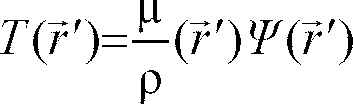
- Equation (4) basically relates how much energy from the
ray 47 interacts with the voxel r'. - A(


- The kernel A(


ray 47 fromexternal radiation source 12 and thus A(

ray 28. Energy conservation requires that:
- That is, if the energy transferred by the primary interaction were all deposited on the interaction point, the kernel would be approximated as a delta function.
- Referring still to Fig. 8, the anisotropy of A(


ray 28 at
patient 17 is irradiated are predetermined, a multi-direction convolution kernel B(


- Referring to Fig. 9, assuming that the spreading of radiation is approximately equal for all beam directions and the
rays 28 from each gantry angle θ contribute equally to the terma at voxel

- For
multiple rays 28 at different gantry angles, the total dose at a given voxel


- This simplification assumes that the contribution to the terma from each
ray 28 is equivalent and takes advantage of the distributive property of convolution. Errors in this assumption are reduced by the filtration to be discussed later. - Equation (7) substantially simplifies the calculation of dose from terma but still requires a convolution for each voxel


- The assumption of the spatial invariance of B(


external radiation source 12 is a complex function of: (1) beam hardening of a polyenergetic x-ray beam (i.e., the effect of the filtration of the patient 17 in increasing the proportion of high frequency or high energy radiation components), (2) the number ofrays 28 crossing each voxel, and (3) exponential attenuation by the patient mass. - In the preferred embodiment, this first factor, beam hardening, is neglected because it is an effect smaller than the attenuation problem. Thus, the photon energy spectrum in the
patient 17 may be assumed to be the same as that of theexternal radiation source 12. This simplification is not required, however, and it will be understood that beam hardening could be accurately accounted for by representing a photon energy spectrum by a finite number of separately convolved energy intervals. - The second factor, the difference in the number and orientation of
rays 28 that cross each voxel, caused by the geometry of a finite number of gantry angles and the fan orientation of thebeam 14, affect spatial invariance. Problems arising from the fan orientation of the beam (in contrast to a parallel beam geometry) are largely solved if there is a full rotation of thegantry 44. Errors resulting from the fact that irradiation is performed at only a finite number of gantry angles have been determined to be acceptable. - The third factor affecting the assumption of spatial invariance is the attenuation of the medium. This affects the fractional contribution of the total terma from the beams at each gantry angle. Accordingly, in those steps of the planning procedure, as will be noted below, where accurate calculation of dose is critical, the dose distribution is calculated separately for each beam based on the attenuation of overlying voxels, such attenuation deduced from the parameters of the tomographic image. In this case the simplification of equation (8) may not be employed and repeated convolutions must be performed. In certain steps in the planning process, however, as will be noted, an estimate is sufficient and in these cases B(


- Production of terma values from a desired dose map 75 is then simply the process of inverting equation (8) as follows:

- This inversion requires that there be no significant "zeros" (typically at high frequencies) in the denominator term F{B(


patients 59 are sufficiently compact to allow this Fourier deconvolution. - Referring now to Fig. 10, this deconvolution to produce a
terma map 82, giving the terma for each voxel
dose map 66, is represented byprocess block 80. - Knowing the
terma map 82, the energy fluence Ψ(

- The value of

process block 84 of Fig. 10, afluence map 86 giving the fluence at each point of the terma map may be determined. - The energy fluence Ψ(


ray 28 exiting thecompensator 22 by the relation:
ray 28 as described by δ(ρ-

compensator 22 and serves to define the fluence profile of the compensator and θ and φ are the gantry angle and the offset angles of theray 28 as previously described. - The exponential term represents the attenuation of the
ray 28 from the exit of thecompensator 22 to the voxel


ray 28, ρ(

compensator 22 and the surface of thepatient 17,

rotation 45 and theray 28. The vector is simply a vector along theray 28 to provide an integration variable. - The fluence at each voxel

radiation beam 14 emitted from thecompensator 22 by equation (11). In the preferred embodiment, the density and attenuation of each voxel


fluence map 86 may be "reverse" back projected (i.e. projected) byprojector 85 to determine a fluence profile to be produced by the external-source necessary to generate the desired fluence map and hence dose. - This projection is simply the opposite of a typical back projection used to form an image of a tomographic slice of a patient 17 from a series of projections taken in a tomographic imaging system. Because a projection is a line integral across a distribution, the energy fluence distribution for each voxel (equation (11)) is first differentiated with respect to the rayline


- The line integral of


- The projection of equation (13) is represented by
projector 85 in Fig. 10. - The projection process, for the purpose of computing fluence profiles for the
compensator 22, differs in a fundamental way from the simple inverse of tomographic back projection. The difference is primarily in a concern for the sharpness in the transition of the dose between the irradiatedtumorous tissue 68 and thehealthy tissue 70. Sharpness in this transition region reduces the irradiation ofhealthy tissue 70 and is preferred over actual fidelity of the dose to the desireddose map 66. - For this reason, the
fluence map 86 from thefluence calculator 84 is prefiltered as shown byprocess block 88 to produce a filtered fluence map Ψ'(φ,θ) as follows:
fluence map 86 and |ω| is a ramp filter in frequency space and the '+' subscript indicates the positive component of the filtering result. Thisprefilter 88 serves to increase the high frequency content of thefluence map 86 and thus to aid in rapid transition of dose at the tumor/non-tumor interface. - It is noted that this
prefilter 88 is similar to the filter used in tomographic imaging's "filtered" back projection. That is, like tomographic imaging, the filter de-emphasizes the low frequency components of the projection in producing image data. In addition other prefilters may be applied to correct for the use of the radially symmetric kernel (equation (6)) in computing the dose map from the terma map composed from the fluence profile. - In practice the computation of a terma map, the generation of a fluence map and the calculation of the fluence profiles need not be performed as discrete steps but may be accomplished by a direct projection of the dose map with appropriate filtering. The filtering is accomplished by a "fast inversion filter" which combines in projection space the operation of deconvolution and ramp filtration.
- This may be symbolically specified by the following equation
 refers to a projection operation and I(t) is the fast inversion filter. The ⊗ operators refers to a convolution operation such as would normally be done in Fourier space using a fast Fourier transformation.
- Referring still to Fig. 10, the fluence profile calculations of
block 78, including thedeconvolver 80, thefluence calculator 84, theprefilter 88 which includes any projection space filter (such as a ramp filter, a fast inversion filter followed by truncation of zeros), and theprojector 85 thus produce fluence profiles which together create an estimated treatment sinogram 87' from the desireddose map 66. Thefluence profile calculator 78 may use the Fourier convolution of equation (9) in the estimate of the fluence profiles at this stage, accepting minor inaccuracies in that process, to be corrected at a later stage, as will be described below. - Referring now to Fig. 11, the
fluence profile calculator 78 converts the desireddose map 66 to an estimated treatment sinogram 87', however the fluence profiles of this estimated treatment sinogram 87' may not be used to control thecompensator 22 because, in general, the estimated treatment sinogram 87' will include positive and negative values of fluence. Only positive values of fluence are physically realizable by thecompensator 22; a negative value of fluence would represent aray 28 that absorbed radiation along its path which is physically unrealizable. - Accordingly, at
process block 88, the fluence values of the estimated treatment sinogram 87' are truncated to positive fluence values 89. As a result of this truncation, the estimated treatment sinogram 87' no longer produces the desired dose map. - The amount of error resulting from the truncation producing the positive fluence profiles 89 is determined by back-projecting the positive fluence values 89 to an actual dose map, 90 deviating from the desired
dose map 66. This back projection is accomplished by computing a fluence map from thepositive fluence values 89 per equation (11) and a terma map per equation (4) and then convolving the terma map with the kernel per equation (7) to establish the actual dose map 90 perprocess block 92 of Fig. 11. - In this back projection, the assumption of spatial invariance of the convolution kernel B(


- The projection of a fluence profile onto a patient 17 to compute a dose map may be performed by a number of other procedures known to those of ordinary skill in the art.
- The actual dose map 90 is compared to the desired
dose map 66 to produceresidual dose map 96 as indicated byprocess block 94. In the preferred embodiment, the comparison subtracts from the values of each voxel
dose map 66, or b) a predetermined upper dose constraint. The predetermined upper dose constraint is a threshold number that is deemed an acceptable dose totumorous tissue 76. Clearly, other methods of quantifying the difference between the desired dose map and the actual dose map will be apparent, from this description, to those of ordinary skill in the art. - The result of this
comparison process 94 is to produce aresidual dose map 96 shown in Fig 12(a). Thisresidual dose map 96 is then, again, operated on by the fluence profile calculator 78 (in lieu of the desired dose map 66) to produce an error fluence profile 98 (in lieu of the estimated treatment sinogram 87). - A thus produced
error fluence profile 98 is subtracted bysubtracter 100 from the estimated treatment sinogram 87' to produce a new estimated treatment sinogram 90. - As shown in Fig. 11, this new estimated
treatment sinogram 87 is repeatedly operated on by process blocks 88, 92, 94 and 78 for a predetermined number of iterations, the magnitude of theerror fluence profile 98 values decreasing with each iteration as shown in Figs. 12(b)-(c) until a suitably lowerror fluence profile 98 is obtained. - The new estimated
fluence profile 87 is then truncated perprocess block 88 to produce afinal sinogram 91 for use in controlling thecompensator 22, as previously described. - Referring again to Figs. 6(b), (c) and (d), dose maps obtained by the present invention corresponding to a desired
dose map 66 of Fig. 6(a) are shown after: one iteration (Fig. 6(b)); two iterations (Fig. 6(c)); and ten iterations (Fig. 6(d)). The variations in dose in the target volume shown in Fig. 6(d) are plus or minus 2% about the predetermined upper limit of 1,000 Cgy. - In order to eliminate radiation hot spots and radiation gaps along the length of a tumor, helical scanning, in which the translation table is continuously moved along a "z axis" through the
gantry 44 as thegantry 44 rotates so that theradiation fan beam 14 sweeps a helical pattern through the tumor site, is desirable. Helical scanners also reduce irradiation time because the start and stop motion of the translation table is eliminated. Nevertheless, because of the constant translation of the patient during helical scanning, the treatment sinogram, as discussed above, must be modified. - Referring to Figs. 13(a)-(c), a simplified
cylindrical tumor 97 with its axis coincident with the axis ofrotation 45 of thegantry 44 has been divided intoseparate slices irradiation window 109 collimated by the opaque mask 16 (shown in Fig. 1) subtends different portions of thetumor 97 as thetumor 97 is translated through thegantry 44 and theradiation source 12 rotates about thetumor 97. - In a helical scan the
irradiation window 109 subtends multiple adjacent slices (i.e. it is not slice specific). Referring to Fig. 13(a) at a 0∞ gantry position, theirradiation window 109 may irradiateonly slice 107. As thetumor 97 is translated and theradiation source 12 rotated, theirradiation window 109 begins to subtend parts of bothslice 107 andadjacent slice 108. Referring to Fig. 13(b), after 90∞ of rotation, theirradiation window 109 may subtend half ofslice 107 and half ofslice 108. Referring to Fig. 13(c), after 180∞ of rotation, theirradiation window 109 only subtendsslice 108. Therefore, helical or non-slice specific data must be developed from theslice sinograms 91 in order to control the compensator leaves 30 during helical irradiation. - Although different portions of a tumor may have different cross sections or density distributions, if slice data is generated that corresponds to many thin tumor slices, the changes in the tumor between adjacent slices will be small. Under these circumstances, fluence profiles for adjacent tumor slices directed along identical gantry angles θ will be substantially similar. Therefore interpolation between adjacent fluence profiles sharing an identical gantry angles θ may be made without appreciably sacrificing irradiation accuracy.
- To convert the final slice sinograms 91 to a continuous fluence profile "ribbon" 93 for easy use in helical scanning, a helical conversion module 95 (see Fig. 11) may use the following weighted averaging equation to make adequate helical fluence profile approximations:

fan beam 14 directed so as to subtend adjacent portions of tumor slices z1 and z2 from gantry angle θj, Ψ(z1,θj) is the fluence profile from thefinal slice sinogram 91 corresponding to slice z1 from gantry angle θj and Ψ(z2,θj) is the fluence profile from theslice sinogram 91 corresponding to slice z2 from gantry angle θj. θj = 0° when the fan beam subtends only slice z1 and changes as the gantry rotates until the fan beam subtends only adjacent slice z2 after 180° of rotation. Therefore, at θj = 0° (see Fig. 13(a)) only Ψ(z1,θj) will influence Ψ(z1,z2,θj). At θj = 90°, (see Fig. 13(b)) when the translation table has moved thetumor 97 one half of a slice thickness so that one half of thefan beam 14 is directed at slice z2, one half of Ψ(z2,θj) and one half of Ψ(z1,θj) will influence Ψ(z1,z2,θj). - After the
fluence profile ribbon 93 is generated, it is stored in themass storage system 64 for later use during a therapy session. - Prior to a therapy session, the
fluence profile ribbon 93 for controlling thecompensator 22 is loaded into thecompensator control 52. Theribbon 93 consists of a plurality of fluence profiles to be directed at the tumor from a sequence of gantry angles θ as the translation table moves through thegantry 44. Each fluence profile consists of desired intensity data for eachray 28 of thefan beam 14. Thecompensator control 52, directed by thefluence profile ribbon 93 data, drives theleaves 30 into and out of theradiation beam 14 effecting various radiation intensities as described above. - Referring to Figs. 3, 4 and 5, as the
compensator control 52 drives theleaves 30 between the open and closed states, thetrigger member 19 of eachleaf 30 is driven in and out of its associatedlight path 33. When thetrigger member 19 blocks the light path 33 (i.e. theleaf 30 is in the closed state), thelight detector 15 produces an actual position signal indicating that theleaf 30 is in the closed position. When thetrigger member 19 is outside the light path 33 (i.e. theleaf 30 is in the open state), thelight detector 15 produces an actual position signal indicating that theleaf 30 is in the open state. - An error detector (not shown) realized in software runs on the
computer 51 and compares the actual position signals to the desired position signals generated by thecompensator control 52 to identify mistakes inleaf 30 movement. If aleaf 30 fails to assume the position indicated by a desired position signal, thecompensator control 52 assumes that theactuator 32 failed. - Upon failure of an
actuator 32, thecompensator control 52 directs its signals so as to bypass theprimary actuator 32 and begin to direct thebackup actuator 35. Thus, a level of redundancy is added to the system wherein failure of a leaf movement means will not require delay in therapy protocol. - In the event that both
actuators spring 39 biases theleaf 30 into the closed state, theleaf 30 thus occluding its associatedray 28. In this manner the possibility of aleaf 30 becoming stuck in an open state so that anuncontrolled ray 28 is directed at the patient is reduced. - The system can be equipped with an alarm to indicate when one or both of the
actuators actuators same leaf 30, a therapy session can continue once theleaf 30 is biased into its closed position. Aclosed leaf 30 poses no danger of radiation overexposure because the associatedbeam ray 28 is entirely occluded. The deficiency in actual radiation absorbed by the tumor because ofleaf 30 failure can be compensated for in later therapy sessions. - Referring now to Fig. 14, there is shown a
simplified compensator 22 andverification system 71 wherein thecompensator 22 has only eight attenuating leaves 30 dividing thefan beam 14 into eightadjacent rays 28. - As part of a
treatment verification system 59, the firstmulti-segment ion chamber 47 disposed between the compensator 22 and thepatient 17 has eightchamber segments 49, eachsegment 49 directly within one of the eightrays 28 of thefan beam 14. Eachsegment 49 produces a measuredray fluence signal 55, or pre-patient fluence signal indicative of the ray fluence encountered thereby. - The second
multi-segment ion chamber 53 disposed within thefan beam 14 opposing theradiation source 12 on the opposite side of thepatient 17 consists of a second group of eightchamber segments 54, eachsegment 54 intercepting oneray 28that passes through the
patient 17. Thesechamber segments 54 produce post-patient fluence signals 57 indicative of the fluence of rays 28' that have traversed the thickness of thepatient 17. - The measured
ray fluences 55 are employed by theverification system 71 for two distinct purposes. First, referring to Fig. 15, acomparator module 101 receives from thecomputer 51 the desired ray fluence to be generated by everyleaf 30 of thecollimator 22. In addition, the comparator module 101 (see Fig. 15) receives the measuredray fluence 55 generated by thefirst ion chamber 49. Comparing the desired ray fluence to the measuredray fluence 55, thecomparator module 101 generates adifference value 102 for eachleaf 30 at each gantry angle θ. - A
limit module 104 determines if thedifference value 102 is outside of a reasonable limit and dangerous to the patient. If so, thecompensator control 52 turns off both the primary 32 andbackup 35 actuators for the duration of the therapy session. With theactuators ray 28 and eliminate possible radiation danger. - If the
difference value 102 is minimal or the measuredray fluence 55 is less than the desired ray fluence, the difference can be corrected by adjusting the ray intensity ofsecond ray 28 and a different gantry angle. - Referring to Fig. 7, and as described above, the total radiation absorbed by a
voxel 74 of the tumor being the summation of radiation directed alongmany rays 28 toward thevoxel 74, discrepancies between desired ray fluence and measuredray fluence 55 can be corrected by adjusting the fluence of thesecond ray 28 adjacent the first ray. Decreasing fluence of asecond ray 28 reduces the quantum of total radiation delivered to avoxel 74. Likewise, increasing fluence of thesecond ray 28 increases the quantum of total radiation delivered to avoxel 74. In this manner, relatively minor discrepancies between desired and measured ray fluences can be eliminated resulting in more accurate therapy sessions. - Second, the measured ray fluence signals 55 are used in conjunction with the post-patient fluence signals 57 to produce tomographic absorption images. By knowing the fluence of each
ray 28 entering thepatient 17 and the fluence of each ray 28' exiting thepatient 17, a simple subtraction calculation generates an absorption value indicating how much radiation is absorbed by the tissue within thepatient 17 traversed by theray 28. By combining all of therays 28 directed along a gantry angle θ while the translation table is in a single position, an absorption profile for that angle θ and table orientation can be constructed. - Data collected during a helical therapy session in which a
fan beam 14 sweeps a helical pattern through a tumor site is not slice specific. Because it is most advantageous to view tomographic images as slices rather than as a helix, the helical data is converted to slice specific data. - The
computer 51 employs thehelical conversion module 95 for a second time to convert the helical data into slice fluence data. Because each tumor slice shares absorption profiles with two adjacent tumor slices (one before and one after), the following weighted averaging equation may be employed:
- After slice absorption profiles corresponding to the various gantry angles θ have been calculated for each tumor slice, tomographic reconstruction techniques may be used to produce a plurality of slice specific tomographic absorption images to be viewed on the
display unit 63. - Standard isodose curve data used in the art for therapy planning purposes can be used by the
computer 51 to establish various levels of radiation absorption along the depth of the tissue traversed by eachray 28. - By back-projecting a plurality of absorption profiles (one profile for every gantry angle θ at which the
beam 14 was directed toward a slice) and simultaneously accounting for the levels of radiation absorption within eachray 28, a tomographic absorption image can be constructed in a manner similar to that used in tomographic x-ray imaging. - A radiologist can use the tomographic absorption images to determine radiation dose absorption within slices of the tumor. These images can also be used to develop more accurate diagnostic techniques and to study the specific effects of irradiation on tumor size and longevity.
- Referring to Fig. 16, a second embodiment of a
radiation therapy unit 110 suitable for use with the present invention includes aradiation source 112 producing a generally conical radiation beam 114' emanating from afocal spot 118 and directed towards a patient (not shown). The conical beam 114' is collimated to form a generallyplanar fan beam 114 centered about afan beam plane 120. - As in the first embodiment, the
compensator 122 is centered in thefan beam 114 and about thefan beam plane 120, prior to the radiation being received by the patient. However, thecompensator 122 of the second embodiment includes arack 124 having anupper level 125 that extends on both sides of thebeam 114, wellpast edges 123 of itsthickness 115. - Referring to Fig. 17 the
upper level 125 of therack 124 has a set ofsleeves 126 that slidably receive a corresponding number of equispaced trapezoidal leaves 128. Eachleaf 128 is constructed of a dense, radio-opaque material such as lead, tungsten, cerium, tantalum or a related alloy. - The
sleeves 126 are constructed of radio-translucent materials and integrally attached to a mountingplate 136 which is fixed relative to thefocal spot 118. The mountingplate 136 is constructed of a sturdy radio-opaque material and is positioned outside thefan beam 114 to prevent interference with thefan beam 114. - The
leaves 128, of the upper level together form an arc of constant radius about thefocal spot 118. When theleaves 128 are in the closed position, aleaf gap 130 slightly less than the width of oneleaf 128 exists between each twoadjacent leaves 128. Theleaves 128 andleaf gaps 130 divide thefan beam 114 into a set of adjacent slab likerays 138 at offset angles. Therays 138 that fall on theleaves 128 are attenuated and those directed between theleaves 128 are passed through theupper level 125 unattenuated. - Referring to Figs. 16 & 17, the
rack 124 also includes alower level 132 that also extends past the edges of thethickness 115 of thebeam 114.Lower level 132 is disposed between theupper level 125 and the patient. Like theupper level 125, thelower level 132 has a second set ofsleeves 135 that receive a corresponding second number of equispaced trapezoidal leaves 134.Leaves 134 are constructed of the same material as leaves 128. - Each
sleeve 135 of thesecond rack 132 is disposed under aleaf gap 130 in theupper level 125 and is centered withinbeam 114. Eachleaf 134 in thelower level 132 is sized to overlap any flankingleaves 128 above it so that when viewed from thefocal spot 118 it eliminates radiation leakage. The overlap, however, ofleaves 128 in theupper level 125 and those in thelower level 132 is slight so that veryfew rays 138 are attenuated by leaves in both racks. Theleaves rays 138 when in the closed position. - Referring now to Figs. 16 and 19(a)-(c), the
sleeves 126, of bothlevels 125 are sized to permit eachleaf 128 to slide to either side of thefan beam 114 completely out of the path of thefan beam 114 yet to still be guided by thesleeve 126. Thesleeve 126, guides theleaf 128, between a "first open state" (Fig. 19(a)), wherein theleaf 128 is positioned to one side of thebeam 114 allowing unobstructed passage of oneray 138 of the beam, and a "closed state" (Fig. 19(b)) in which theleaf 128 is positioned in the center of thesleeve 126 occluding oneray 138 of the beam, and a "second open state" (Fig. 19(c)), in which theleaf 128 on the opposite side of thebeam 114 allowing unobstructed passage of theray 138 of the beam. - Referring now to Fig. 18, the
leaves sleeves guide rails 137 fitted intonotches 142 cut along the edges of theleaves notches 142 allow theguide rails 137 to slidably retain theleaves sleeves - Referring again to Fig. 16, each
leaf pneumatic cylinder 139 connected to theleaf flexible link 140. Thepneumatic cylinders 139 have internal pistons (not shown) that may be moved at high velocity between the ends of thecylinders 139 by means of pressurized air coupled to thecylinders 139 throughsupply hoses 141. Thesupply hoses 141 are fed by a compensator control (not shown in Figs. 16 or 17) to be described below. Thepneumatic cylinders 139 are capable of applying high forces to theleaves - As best seen in Figs. 16 & 17, two solenoid stops 143 are associated with each
leaf sleeve 126 on theupper level 125, with onestop 143 outside eachedge 123 of thebeam thickness 115.Similar assemblies 143 are disposed below eachsleeve 135 on thelower level 132, one outside eachedge 123 of thebeam thickness 115. The solenoid stops 143 are used to ensure accurate positioning of theleaves fan beam 114 in a manner to be described in more detail below. - Referring to Fig. 20, each
stop 143 has anelectrical solenoid coil 144 which, when energized, attracts a concentrically locatedarmature 145 against the force of aspring 150. Aflexible connector 147 connects thearmature 145 to a stoppingshaft 148 protruding from thestop 143 to be retracted by the armature when the coil is energized. Eachsolenoid stop 143 is securely fastened to its respective level of therack 124 by a mountingbracket 146. Aflange 149 on thearmature 145 holds thespring 150 between itself and the underside of thecoil 145 to bias the stoppingshaft 148 out from thestop 143 when thecoil 144 is de-energized. - The
flexible connector 147 is longitudinally rigid, but laterally flexible to absorb the torque applied to the stoppingshaft 148 by impact with its associatedleaf shaft 148 is constructed of a rigid but resilient material that will not bend under the pressure of repeated collisions with acollimator leaf - As seen in Fig. 19(b), when the
solenoid coil 144 is not energized, thespring 150 biases thearmature 145 out from thecoil 144 which in turn forces the stoppingshaft 148 through ashaft hole 153 in therack 124, and into thesleeve 126, into the path of leaf movement. When thesolenoid coil 144 is energized, thearmature 45 retracts into thecoil 144 and out of the path of leaf movement. - Referring now to Figs. 19(a)-(c), during radiation therapy, the
stops 143 remain de-energized most of the time with the stoppingshafts 148 protruding into the sleeves and thus locking their associatedleaf 128 into one of its three steady state positions, the closed position (19(b)) the first open position (19(a)) and the second open position (19(c)). - When a leaf is to move from the first open position (Fig. 19(a)) to the closed position (Fig. 19(b)), the compensator control module 158 first energizes a
first solenoid stop 143a which moves a stopping shaft 148a up and out of thesleeve 126 allowing the leaf to move toward the closed position. High pressure air directed to thepneumatic cylinder 139 then pushing theleaf 128 toward the closed position (see Fig. 19(b)). Theleaf 128 strikes the second stoppingshaft 148b where it is halted in the closed position occluding theentire thickness 115 of theray 138. Stopping shaft 148(b) ensures theleaf 128 is accurately positioned. Thefirst solenoid stop 143a is then deenergized and the compressively loadedspring 150 expands forcing the stopping shaft 148a down back into thesleeve 126. At this point, the stoppingshafts 148a, 148b of bothsolenoid stops sleeve 126 and abutting the edges of theleaf 128. With bothsolenoid stops leaf 128 is secured in the closed position against perturbing forces. - Similarly, to move the
leaf 128 into the second open position, thesecond stop 143b is energized and the stoppingshaft 148b is pulled out of thesleeve 126. Theleaf 128 is pushed to the second open position (see Fig. 19(c)). Thesecond stop 143b is de-energized and the stoppingshaft 148b is forced into thesleeve 126 to lock theleaf 128 out of the beam. - As will now be described, by alternating open states from one side of the
beam thickness 115 to the other, the characteristic gradient attenuation along thethickness 115 of the ray 138 (i.e. the beam 114) can be eliminated. - Referring now to Fig. 21(a), when the
leaf 128 is in the closed state, entirely occluding thefan beam thickness 115 the initial cumulative intensity of radiation received by the patient is zero. As theleaf 128 is moving to the first open state (see Fig. 21(b)), the cumulative intensity of the received radiation increases starting with the first areas to be exposed. By the time theleaf 128 reaches the first open state in Fig. 21(c), there is a gradient of receivedradiation 121 across thebeam thickness 115. - As the
leaf 128 begins to return to the closed state as in Fig. 21(d), thegradient attenuation 121 becomes steeper until it is twice as steep as it was after the first open cycle (see Fig. 21(e)). - In the next cycle, the
leaf 128 is moved to the second open state as in Fig. 21(f), the exact direction as the previous cycle producing theopposite gradient 121. When the gradients of the two cycles add together, the resultingcumulative intensity 119 of the rays directed across thebeam thickness 115 becomes uniform as in Fig. 21(g). - Referring again to Figs. 19(a)-(c), it should be noted that alternating movement of a
leaf 128, results in a uniform radiation exposure across the thickness of thebeam 115 only if the velocity of theleaf 128 is constant as theleaf 128 travels through thebeam thickness 115. Without a constant leaf velocity, a parabolic exposure profile across thebeam thickness 115 results as the exposure of alternating open cycles is added. - While, practically, some acceleration of the
leaf 128 as it travels through the beam widths will be acceptable, ideally, most of the acceleration of theleaf 128 will take place while thebeam 114 is either fully occluded or entirely unattenuated. Leaf acceleration can be limited to these two conditions by placing thesolenoid stop 143 outside thebeam thickness 115 and configuring theleaf 128 to be wider than thebeam thickness 115 so as to provide for a first 133a and a second 133b acceleration gap on opposite sides of thebeam thickness 115. - Referring still to Figs. 19(a)-(c), when the
leaf 128 moves from the first open state (Fig. 19(a)) to the closed state (Fig. 19(b)), it is accelerated from a stationary position to a constant velocity before theleading edge 129 of theleaf 128 passes the first acceleration gap 133a and enters thebeam thickness 115. As theleading edge 129 moves across thebeam thickness 115 its velocity is constant until it strikes the second stoppingshaft 148b. Theleaf 128 is decelerated after theleading edge 129 is within the second acceleration gap 133b and thefollowing edge 131 is within the first acceleration gap 133a. - In the closed position (Fig. 19(b)), the
leaf 128 occludes theentire beam thickness 115 as well as both acceleration gaps 133a, 133b. Moving from the closed state (Fig. 19(b)), to the second open state (Fig. 19(c)), theleaf 128 is accelerated from its closed stationary position to a constant velocity before thefollowing edge 131 exits the first acceleration gap 133a. Restricting acceleration and deceleration to the period when the leaf edges 129, 131 are within the acceleration gaps is also observed when moving from the second open state to the closed state and from the closed state to the first open state. - It has been found that the optimal acceleration gap 133 size is independent of acceleration potential and is one fourth the beam thickness 115 (see Appendix). Therefore, in order for the
leaf 128 to occlude both thebeam thickness 115 and both acceleration gaps 133 when in the closed state, theleaf 128 should ideally be constructed 1.5 times as long as the beam thickness 115 (see Figs. 19(a)-(c)). - Using a
leaf 128 that is wider thanbeam thickness 115 enables thestops 143 to provide a simple leaf deceleration mechanism. When theleaf 128 is moved from its first open state (Fig. 19(a)) to the closed state (Fig. 19(b)), upon impact with the stoppingshaft 148b, theleaf 128 may temporarily bounce back off the stoppingshaft 148b. Piston pressure is continued to limit "leaf bounce" to positions in which the impactingleaf edge 129 remaining within its associated leaf gap 133b. Thus, leaf deceleration will be limited toacceptable leaf 128 positions. - Preferably, this
second compensator embodiment 110 employs the radiation therapy hardware discussed above in connection with Fig. 5, and utilizes the therapy planning software discussed above in connection with Figs. 10 and 11. - The above description has been that of a preferred embodiment of the present invention. It will occur to those who practice the art that many modifications may be made without departing from the spirit and scope of the invention. For example, the image reconstructor 60 could produce a tomographic desired fluence image for comparison with the tomographic absorption image to produce a tomographic irradiation error image. The error image could then be used to repeat the helical irradiation process to correct for insufficient irradiation. Clearly the method for planning radiation therapy is not limited to a particular radiation source but may be used with any radiation source which may be decomposed into separately attenuated radiation rays. In addition, a computed tomography system need not be incorporated with the radiation therapy equipment but separate such equipment could be used. The relationship between the terma values and the fluence values may assume a constant density of the patient to eliminate the need for a precise tomographic scan of the irradiated area.
- It should also be recognized that the
pneumatic cylinders 139 in the second embodiment could be constructed to decelerate theleaves leaf 128 is moved from the first open state (Fig. 19(a)) to the closed state (Fig. 19(b)), once theleading edge 129 is through thebeam thickness 114, the associatedpneumatic cylinder 139 could produce a breaking pulse that slows theleaf 128 before theleading edge 129 impacts the stoppingshaft 148b. Similar deceleration pulses could be utilized at the end of each leaf movement to limit leaf and stopping shaft wear. In order to apprise the public of the various embodiments that may fall within the scope of the invention, the following claims are made:


Claims (3)
- In a radiation therapy machine having a radiation source for producing a radiation beam directed toward a patient at a gantry angle, the beam including a plurality of adjacent rays, the machine having an attenuating means disposed between the radiation source and the patient for independently controlling the fluence of each ray of the beam, a verification system comprising:a pre-patient monitor generally disposed between the attenuating means and the patient for determining a pre-patient fluence of each ray of the beam prior to entering the patient; anda post-patient monitor generally disposed opposite the pre-patient monitor with respect to the patient and within the fan beam for determining a post-patient fluence of each ray of the beam exiting the patient.
- The system recited in claim 1 further comprising an absorption calculator for comparing the pre-patient fluence to the post-patient fluence to produce an absorption value for each ray, the absorption values together providing an absorption profile for the fan beam at a given gantry angle.
- The system recited in claim 2 further comprising:a reconstruction means receiving absorption profiles from a plurality of gantry angles to create a tomographic absorption image of the patient.
Applications Claiming Priority (5)
| Application Number | Priority Date | Filing Date | Title |
|---|---|---|---|
| US08/074,185 US5394452A (en) | 1992-03-19 | 1993-06-09 | Verification system for radiation therapy |
| US08/071,743 US5351280A (en) | 1992-03-19 | 1993-06-09 | Multi-leaf radiation attenuator for radiation therapy |
| US74185 | 1993-06-09 | ||
| US71743 | 1993-06-09 | ||
| EP94920712A EP0703806B1 (en) | 1993-06-09 | 1994-06-08 | Multi-leaf radiation attenuator for radiation therapy with verification system |
Related Parent Applications (2)
| Application Number | Title | Priority Date | Filing Date |
|---|---|---|---|
| EP94920712A Division EP0703806B1 (en) | 1993-06-09 | 1994-06-08 | Multi-leaf radiation attenuator for radiation therapy with verification system |
| EP94920712.0 Division | 1994-12-22 |
Publications (3)
| Publication Number | Publication Date |
|---|---|
| EP0773042A2 true EP0773042A2 (en) | 1997-05-14 |
| EP0773042A3 EP0773042A3 (en) | 1999-04-28 |
| EP0773042B1 EP0773042B1 (en) | 2004-10-06 |
Family
ID=26752614
Family Applications (3)
| Application Number | Title | Priority Date | Filing Date |
|---|---|---|---|
| EP97100108A Expired - Lifetime EP0773042B1 (en) | 1993-06-09 | 1994-06-08 | Multi-leaf radiation attenuator for radiation therapy with verification system |
| EP97118687A Expired - Lifetime EP0832669B1 (en) | 1993-06-09 | 1994-06-08 | Multi-leaf radiation attenuator for radiation therapy with verification system |
| EP94920712A Expired - Lifetime EP0703806B1 (en) | 1993-06-09 | 1994-06-08 | Multi-leaf radiation attenuator for radiation therapy with verification system |
Family Applications After (2)
| Application Number | Title | Priority Date | Filing Date |
|---|---|---|---|
| EP97118687A Expired - Lifetime EP0832669B1 (en) | 1993-06-09 | 1994-06-08 | Multi-leaf radiation attenuator for radiation therapy with verification system |
| EP94920712A Expired - Lifetime EP0703806B1 (en) | 1993-06-09 | 1994-06-08 | Multi-leaf radiation attenuator for radiation therapy with verification system |
Country Status (6)
| Country | Link |
|---|---|
| US (2) | US5394452A (en) |
| EP (3) | EP0773042B1 (en) |
| JP (1) | JP3553943B2 (en) |
| DE (3) | DE69433954T2 (en) |
| IL (1) | IL109962A (en) |
| WO (1) | WO1994028974A2 (en) |
Cited By (5)
| Publication number | Priority date | Publication date | Assignee | Title |
|---|---|---|---|---|
| WO1999036885A1 (en) * | 1998-01-13 | 1999-07-22 | Koninklijke Philips Electronics N.V. | Computer tomagraphy method with helicoidal scanning of an examination area |
| EP1020204A1 (en) * | 1999-01-15 | 2000-07-19 | Scanditronix Medical AB | Method for calibrating a detector means for radiation dosimetry |
| US6298115B1 (en) | 2000-01-13 | 2001-10-02 | Scanditronix Medical Ab | Method for calibrating a detector means |
| WO2002022210A1 (en) * | 2000-09-15 | 2002-03-21 | Deutsches Krebsforschungszentrum Stiftung des öffentlichen Rechts | Method and device for verifying a therapeutic irradiation |
| GB2358337B (en) * | 1999-10-06 | 2003-10-15 | Siemens Medical Systems Inc | Method and system for verification of different types of beam limiting devices in a linear accelerator utilized for radiotherapy |
Families Citing this family (152)
| Publication number | Priority date | Publication date | Assignee | Title |
|---|---|---|---|---|
| US5317616A (en) * | 1992-03-19 | 1994-05-31 | Wisconsin Alumni Research Foundation | Method and apparatus for radiation therapy |
| US5596619A (en) * | 1992-08-21 | 1997-01-21 | Nomos Corporation | Method and apparatus for conformal radiation therapy |
| US5418827A (en) * | 1993-06-18 | 1995-05-23 | Wisconsin Alumino Research Foundation | Method for radiation therapy planning |
| US5528651A (en) * | 1994-06-09 | 1996-06-18 | Elekta Instrument Ab | Positioning device and method for radiation treatment |
| DE19508228B4 (en) * | 1995-03-08 | 2005-12-29 | Brainlab Ag | Method for irradiating a target point located in a target object |
| US5555283A (en) * | 1995-06-07 | 1996-09-10 | Board Of Regents Of The University Of Texas System | Computer-controlled miniature multileaf collimator |
| US6345114B1 (en) * | 1995-06-14 | 2002-02-05 | Wisconsin Alumni Research Foundation | Method and apparatus for calibration of radiation therapy equipment and verification of radiation treatment |
| US5754622A (en) * | 1995-07-20 | 1998-05-19 | Siemens Medical Systems, Inc. | System and method for verifying the amount of radiation delivered to an object |
| US5591983A (en) * | 1995-06-30 | 1997-01-07 | Siemens Medical Systems, Inc. | Multiple layer multileaf collimator |
| US5847403A (en) * | 1995-06-30 | 1998-12-08 | Siemens Medical Systems, Inc. | System and method for reducing radiation leakage with intensity modulated treatments |
| US5724403A (en) * | 1995-07-20 | 1998-03-03 | Siemens Medical Systems, Inc. | Virtual compensator |
| GB9520564D0 (en) * | 1995-10-07 | 1995-12-13 | Philips Electronics Nv | Apparatus for treating a patient |
| US5818902A (en) * | 1996-03-01 | 1998-10-06 | Elekta Ab | Intensity modulated arc therapy with dynamic multi-leaf collimation |
| US5602892A (en) * | 1996-03-21 | 1997-02-11 | Llacer; Jorge | Method for optimization of radiation therapy planning |
| IL119283A0 (en) * | 1996-09-19 | 1996-12-05 | Elscint Ltd | Adaptive filtering |
| JP2001507954A (en) * | 1996-10-24 | 2001-06-19 | ノモス・コーポレーシヨン | Method and apparatus for determining radiation dose |
| US6005919A (en) | 1996-10-25 | 1999-12-21 | Radionics, Inc. | Jaw and circular collimator |
| WO1998030980A1 (en) * | 1997-01-14 | 1998-07-16 | Edholm, Paul | Technique and arrangement for tomographic imaging |
| US5771270A (en) * | 1997-03-07 | 1998-06-23 | Archer; David W. | Collimator for producing an array of microbeams |
| US6052430A (en) * | 1997-09-25 | 2000-04-18 | Siemens Medical Systems, Inc. | Dynamic sub-space intensity modulation |
| IL121866A (en) | 1997-09-29 | 2000-11-21 | Ein Gal Moshe | Multiple layer multileaf collimator |
| US6636622B2 (en) | 1997-10-15 | 2003-10-21 | Wisconsin Alumni Research Foundation | Method and apparatus for calibration of radiation therapy equipment and verification of radiation treatment |
| US6222544B1 (en) * | 1997-10-17 | 2001-04-24 | Siemens Medical Systems, Inc. | Graphical user interface for radiation therapy treatment apparatus |
| US6393096B1 (en) | 1998-05-27 | 2002-05-21 | Nomos Corporation | Planning method and apparatus for radiation dosimetry |
| WO2000007667A1 (en) * | 1998-08-06 | 2000-02-17 | Wisconsin Alumni Research Foundation | Radiotherapy verification system |
| DE19904972A1 (en) * | 1999-02-06 | 2000-08-17 | Deutsches Krebsforsch | Contour collimator for radiation therapy |
| DE19912708A1 (en) * | 1999-03-20 | 2000-09-28 | Deutsches Krebsforsch | Method to control position of patient for high-energy X-ray therapy; involves obtaining partial data set or section image to determine exact position with respect to radiation field |
| US6459769B1 (en) | 1999-05-03 | 2002-10-01 | Sherwood Services Ag | Movable miniature multi-leaf collimator |
| EP3620210A1 (en) * | 2000-02-18 | 2020-03-11 | William Beaumont Hospital | Cone-beam computerized tomography with a flat-panel imager |
| US6504898B1 (en) * | 2000-04-17 | 2003-01-07 | Mds (Canada) Inc. | Product irradiator for optimizing dose uniformity in products |
| GB2362080B (en) | 2000-04-28 | 2003-12-10 | Elekta Ab | Multi-leaf collimator |
| EP1309372A2 (en) * | 2000-08-17 | 2003-05-14 | Radiological Imaging Technology, Inc. | Interrupted radiation treatment quality assurance |
| US6853702B2 (en) * | 2000-12-15 | 2005-02-08 | Wendel Dean Renner | Radiation therapy dosimetry quality control process |
| US7046831B2 (en) * | 2001-03-09 | 2006-05-16 | Tomotherapy Incorporated | System and method for fusion-aligned reprojection of incomplete data |
| US6661870B2 (en) | 2001-03-09 | 2003-12-09 | Tomotherapy Incorporated | Fluence adjustment for improving delivery to voxels without reoptimization |
| CN100464377C (en) * | 2001-10-23 | 2009-02-25 | 深圳市一体智能技术有限公司 | Blade regulating method of multi-blade collimator and multi-blade collimator |
| US6888919B2 (en) * | 2001-11-02 | 2005-05-03 | Varian Medical Systems, Inc. | Radiotherapy apparatus equipped with an articulable gantry for positioning an imaging unit |
| DE10154481B4 (en) * | 2001-11-08 | 2005-02-10 | Siemens Ag | Medical X-ray system with a device for filtering an X-ray beam |
| US7016522B2 (en) * | 2002-01-15 | 2006-03-21 | Siemens Medical Solutions Usa, Inc. | Patient positioning by video imaging |
| JP4686128B2 (en) * | 2002-03-06 | 2011-05-18 | トモセラピー インコーポレイテッド | Radiation delivery apparatus control method and radiation therapy delivery system |
| US7227925B1 (en) | 2002-10-02 | 2007-06-05 | Varian Medical Systems Technologies, Inc. | Gantry mounted stereoscopic imaging system |
| US7657304B2 (en) | 2002-10-05 | 2010-02-02 | Varian Medical Systems, Inc. | Imaging device for radiation treatment applications |
| US7945021B2 (en) | 2002-12-18 | 2011-05-17 | Varian Medical Systems, Inc. | Multi-mode cone beam CT radiotherapy simulator and treatment machine with a flat panel imager |
| US20040254448A1 (en) * | 2003-03-24 | 2004-12-16 | Amies Christopher Jude | Active therapy redefinition |
| GB0310596D0 (en) * | 2003-05-08 | 2003-06-11 | Cancer Res Inst | Method and apparatus for producing an intensity modulated beam of radiation |
| CN101006541B (en) * | 2003-06-02 | 2010-07-07 | 福克斯·彻斯癌症中心 | High energy polyenergetic ion selection systems, ion beam therapy systems, and ion beam treatment centers |
| US7412029B2 (en) | 2003-06-25 | 2008-08-12 | Varian Medical Systems Technologies, Inc. | Treatment planning, simulation, and verification system |
| WO2005081842A2 (en) * | 2004-02-20 | 2005-09-09 | University Of Florida Research Foundation, Inc. | System for delivering conformal radiation therapy while simultaneously imaging soft tissue |
| US7366279B2 (en) * | 2004-07-29 | 2008-04-29 | General Electric Company | Scatter control system and method for computed tomography |
| US7957507B2 (en) * | 2005-02-28 | 2011-06-07 | Cadman Patrick F | Method and apparatus for modulating a radiation beam |
| US20070003010A1 (en) | 2005-04-29 | 2007-01-04 | Varian Medical Systems Technologies, Inc. | Radiation systems with imaging capability |
| US8232535B2 (en) * | 2005-05-10 | 2012-07-31 | Tomotherapy Incorporated | System and method of treating a patient with radiation therapy |
| WO2007014110A2 (en) | 2005-07-22 | 2007-02-01 | Tomotherapy Incorporated | Method and system for evaluating delivered dose |
| US8442287B2 (en) * | 2005-07-22 | 2013-05-14 | Tomotherapy Incorporated | Method and system for evaluating quality assurance criteria in delivery of a treatment plan |
| KR20080049716A (en) | 2005-07-22 | 2008-06-04 | 토모테라피 인코포레이티드 | Method and system for evaluating quality assurance criteria in delivery of a treament plan |
| KR20080039924A (en) | 2005-07-22 | 2008-05-07 | 토모테라피 인코포레이티드 | System and method of generating contour structures using a dose volume histogram |
| DE602006021803D1 (en) | 2005-07-22 | 2011-06-16 | Tomotherapy Inc | A system for delivering radiotherapy to a moving target area |
| US7567694B2 (en) | 2005-07-22 | 2009-07-28 | Tomotherapy Incorporated | Method of placing constraints on a deformation map and system for implementing same |
| WO2007014107A2 (en) * | 2005-07-22 | 2007-02-01 | Tomotherapy Incorporated | System and method of monitoring the operation of a medical device |
| US20070041496A1 (en) * | 2005-07-22 | 2007-02-22 | Olivera Gustavo H | System and method of remotely analyzing operation of a radiation therapy system |
| KR20080044252A (en) * | 2005-07-22 | 2008-05-20 | 토모테라피 인코포레이티드 | Method and system for processing data relating to a radiation therapy treatment plan |
| US7639853B2 (en) * | 2005-07-22 | 2009-12-29 | Tomotherapy Incorporated | Method of and system for predicting dose delivery |
| EP1907065B1 (en) | 2005-07-22 | 2012-11-07 | TomoTherapy, Inc. | Method and system for adapting a radiation therapy treatment plan based on a biological model |
| CA2616136A1 (en) * | 2005-07-22 | 2007-02-01 | Tomotherapy Incorporated | System and method of evaluating dose delivered by a radiation therapy system |
| JP2009502253A (en) * | 2005-07-22 | 2009-01-29 | トモセラピー・インコーポレーテッド | System and method for applying radiation therapy to a moving region of interest |
| JP5390855B2 (en) | 2005-07-23 | 2014-01-15 | トモセラピー・インコーポレーテッド | Imaging and delivery of radiation therapy using coordinated movement of gantry and treatment table |
| US20090041200A1 (en) * | 2005-07-23 | 2009-02-12 | Tomotherapy Incorporated | Radiation therapy imaging and delivery utilizing coordinated motion of jaws, gantry, and couch |
| US7880154B2 (en) | 2005-07-25 | 2011-02-01 | Karl Otto | Methods and apparatus for the planning and delivery of radiation treatments |
| EP1747799A1 (en) * | 2005-07-27 | 2007-01-31 | Ion Beam Applications S.A. | Dosimetry device for verification of a radiation therapy apparatus |
| US7298821B2 (en) * | 2005-12-12 | 2007-11-20 | Moshe Ein-Gal | Imaging and treatment system |
| JP4703421B2 (en) * | 2006-02-02 | 2011-06-15 | 株式会社東芝 | Multi-leaf collimator and radiotherapy apparatus provided with the same |
| US9339243B2 (en) | 2006-04-14 | 2016-05-17 | William Beaumont Hospital | Image guided radiotherapy with dual source and dual detector arrays tetrahedron beam computed tomography |
| US8983024B2 (en) | 2006-04-14 | 2015-03-17 | William Beaumont Hospital | Tetrahedron beam computed tomography with multiple detectors and/or source arrays |
| EP2010058B1 (en) * | 2006-04-14 | 2017-05-17 | William Beaumont Hospital | Computed Tomography System and Method |
| US9192786B2 (en) * | 2006-05-25 | 2015-11-24 | William Beaumont Hospital | Real-time, on-line and offline treatment dose tracking and feedback process for volumetric image guided adaptive radiotherapy |
| JP2008006032A (en) * | 2006-06-29 | 2008-01-17 | Ge Medical Systems Global Technology Co Llc | X-ray ct scanner and x-ray ct scanning method |
| CN101610811A (en) * | 2006-07-28 | 2009-12-23 | 断层放疗公司 | Be used to calibrate the method and apparatus of radiation therapy treatment system |
| US20080043910A1 (en) * | 2006-08-15 | 2008-02-21 | Tomotherapy Incorporated | Method and apparatus for stabilizing an energy source in a radiation delivery device |
| EP1917998A1 (en) * | 2006-11-03 | 2008-05-07 | Ion Beam Applications S.A. | Method and device for online IMRT verification |
| EP1917999A1 (en) * | 2006-11-03 | 2008-05-07 | Ion Beam Applications S.A. | Method and device for IMRT verification |
| EP2088925B8 (en) | 2006-11-17 | 2015-06-17 | Varian Medical Systems, Inc. | Dynamic patient positioning system |
| US7977657B2 (en) * | 2007-02-27 | 2011-07-12 | Wisconsin Alumni Research Foundation | Ion radiation therapy system with distal gradient tracking |
| WO2008106500A1 (en) * | 2007-02-27 | 2008-09-04 | Wisconsin Alumni Research Foundation | Fan beam modulator for ion beams providing continuous intensity modulation |
| US8129701B2 (en) * | 2007-02-27 | 2012-03-06 | Al-Sadah Jihad H | Areal modulator for intensity modulated radiation therapy |
| WO2008106488A1 (en) | 2007-02-27 | 2008-09-04 | Wisconsin Alumni Research Foundation | Ion radiation therapy system having magnetic fan beam former |
| US7714309B2 (en) * | 2007-02-27 | 2010-05-11 | Wisconsin Alumni Research Foundation | Phantom for ion range detection |
| EP2114529B1 (en) * | 2007-02-27 | 2011-06-08 | Wisconsin Alumni Research Foundation | Heavy ion radiation therapy system with stair-step modulation |
| US8093568B2 (en) * | 2007-02-27 | 2012-01-10 | Wisconsin Alumni Research Foundation | Ion radiation therapy system with rocking gantry motion |
| WO2008106496A1 (en) * | 2007-02-27 | 2008-09-04 | Wisconsin Alumni Research Foundation | Ion radiation therapy system with variable beam resolution |
| US7977648B2 (en) * | 2007-02-27 | 2011-07-12 | Wisconsin Alumni Research Foundation | Scanning aperture ion beam modulator |
| WO2008106522A2 (en) * | 2007-02-27 | 2008-09-04 | Wisconsin Alumni Research Foundation | System and method for optimization of a radiation therapy plan in the presence of motion |
| USRE46953E1 (en) | 2007-04-20 | 2018-07-17 | University Of Maryland, Baltimore | Single-arc dose painting for precision radiation therapy |
| EP2185075A4 (en) * | 2007-09-04 | 2011-05-18 | Tomotherapy Inc | Patient support device |
| WO2009055775A2 (en) * | 2007-10-25 | 2009-04-30 | Tomotherapy Incorporated | Method for adapting fractionation of a radiation therapy dose |
| US20090121155A1 (en) * | 2007-11-09 | 2009-05-14 | Elekta Ab (Publ) | Radiotherapy apparatus and parts thereof |
| US8130905B1 (en) * | 2007-11-21 | 2012-03-06 | Sun Nuclear Corporation | Dosimetry system and method for radiation therapy |
| GB2457483A (en) * | 2008-02-15 | 2009-08-19 | Elekta Ab | Multi-leaf collimator |
| JP2011512999A (en) * | 2008-03-04 | 2011-04-28 | トモセラピー・インコーポレーテッド | Improved image segmentation method and system |
| US8017915B2 (en) | 2008-03-14 | 2011-09-13 | Reflexion Medical, Inc. | Method and apparatus for emission guided radiation therapy |
| WO2010025372A2 (en) * | 2008-08-28 | 2010-03-04 | Tomotherapy Incorporated | System and method of contouring a target area |
| WO2010025399A2 (en) | 2008-08-28 | 2010-03-04 | Tomotherapy Incorporated | System and method of calculating dose uncertainty |
| US8611496B2 (en) * | 2008-11-12 | 2013-12-17 | University Of Tsukuba | Radiation treatment system |
| EP2403600A4 (en) * | 2009-03-03 | 2012-08-29 | Tomotherapy Inc | System and method of optimizing a heterogeneous radiation dose to be delivered to a patient |
| CN101989468B (en) * | 2009-08-06 | 2015-04-22 | 连卫东 | Array intensity modulation collimator |
| WO2011041412A2 (en) * | 2009-09-29 | 2011-04-07 | Tomotherapy Incorporated | Patient support device with low attenuation properties |
| WO2011053802A2 (en) * | 2009-10-30 | 2011-05-05 | Tomotherapy Incorporated | Non-voxel-based broad-beam (nvbb) algorithm for intensity modulated radiation therapy dose calculation and plan optimization |
| EP2521592A4 (en) | 2010-01-05 | 2013-12-18 | Beaumont Hospital William | Intensity modulated arc therapy with continuous couch rotation/shift and simultaneous cone beam imaging |
| US9289627B2 (en) | 2010-06-22 | 2016-03-22 | Varian Medical Systems International Ag | System and method for estimating and manipulating estimated radiation dose |
| CN103650095B (en) | 2011-03-31 | 2016-12-07 | 反射医疗公司 | For the system and method used in launching the radiotherapy guided |
| US10561861B2 (en) | 2012-05-02 | 2020-02-18 | Viewray Technologies, Inc. | Videographic display of real-time medical treatment |
| US9586060B2 (en) | 2012-05-29 | 2017-03-07 | The Royal Institution For The Advancement Of Learning/Mcgill University | Method and system for calorimetry probe |
| JP5338000B1 (en) * | 2012-06-15 | 2013-11-06 | 株式会社アキュセラ | Real-time 3D radiotherapy device |
| EP2687260A1 (en) | 2012-07-19 | 2014-01-22 | Deutsches Krebsforschungszentrum | Leaf assembly for a multi-leaf collimator and multi-leaf collimator |
| EP2687259A1 (en) * | 2012-07-19 | 2014-01-22 | Deutsches Krebsforschungszentrum | Leaf module for a multi-leaf collimator and multi-leaf collimator |
| US9097642B2 (en) * | 2012-10-11 | 2015-08-04 | General Electric Company | X-ray dose estimation technique |
| EP3628370A1 (en) | 2012-10-26 | 2020-04-01 | ViewRay Technologies, Inc. | Assessment and improvement of treatment using imaging of physiological responses to radiation therapy |
| WO2014133849A2 (en) * | 2013-02-26 | 2014-09-04 | Accuray Incorporated | Electromagnetically actuated multi-leaf collimator |
| JP5805689B2 (en) * | 2013-03-08 | 2015-11-04 | 株式会社モリタ製作所 | X-ray CT imaging apparatus and X-ray CT imaging method |
| US9446263B2 (en) | 2013-03-15 | 2016-09-20 | Viewray Technologies, Inc. | Systems and methods for linear accelerator radiotherapy with magnetic resonance imaging |
| US9844358B2 (en) * | 2014-06-04 | 2017-12-19 | Varian Medical Systems, Inc. | Imaging-based self-adjusting radiation therapy systems, devices, and methods |
| WO2016100739A1 (en) | 2014-12-19 | 2016-06-23 | Sun Nuclear Corporation | Radiation therapy dose calculation |
| US10617891B2 (en) | 2015-04-23 | 2020-04-14 | Sun Nuclear Corporation | Radiation detector calibration |
| US10500416B2 (en) * | 2015-06-10 | 2019-12-10 | Reflexion Medical, Inc. | High bandwidth binary multi-leaf collimator design |
| US9795805B2 (en) * | 2015-09-25 | 2017-10-24 | Varian Medical Systems, Inc. | Proton therapy multi-leaf collimator beam shaping |
| US9966160B2 (en) * | 2015-11-24 | 2018-05-08 | Viewray Technologies, Inc. | Radiation beam collimating systems and methods |
| AU2017227590A1 (en) | 2016-03-02 | 2018-08-30 | Viewray Technologies, Inc. | Particle therapy with magnetic resonance imaging |
| EP3426345B1 (en) | 2016-03-09 | 2021-06-23 | RefleXion Medical, Inc. | Fluence map generation methods for radiotherapy |
| CN115407252A (en) | 2016-06-22 | 2022-11-29 | 优瑞技术公司 | Low field strength magnetic resonance imaging |
| EP3490672B1 (en) | 2016-07-28 | 2021-03-03 | Sun Nuclear Corporation | Beam angle direction determination |
| US10806409B2 (en) | 2016-09-23 | 2020-10-20 | Varian Medical Systems International Ag | Medical systems with patient supports |
| JP7178714B2 (en) | 2016-11-15 | 2022-11-28 | リフレクション メディカル, インコーポレイテッド | Radiation Therapy Patient Platform |
| EP3988017A1 (en) | 2016-11-15 | 2022-04-27 | RefleXion Medical, Inc. | System for emission-guided high-energy photon delivery |
| WO2018093849A1 (en) | 2016-11-15 | 2018-05-24 | Reflexion Medical, Inc. | Methods for radiation delivery in emission-guided radiotherapy |
| BR112019012061A2 (en) | 2016-12-13 | 2019-11-12 | Viewray Tech Inc | radiation therapy systems and methods |
| US10850120B2 (en) | 2016-12-27 | 2020-12-01 | Varian Medical Systems International Ag | Selecting a dose prediction model based on clinical goals |
| US10512790B2 (en) | 2017-01-11 | 2019-12-24 | Varian Medical Systems International Ag. | Systems and methods for generating radiation treatment plans |
| EP3589366A1 (en) | 2017-02-28 | 2020-01-08 | Sun Nuclear Corporation | Radiation therapy treatment verification with electronic portal imaging device transit images |
| US10188873B2 (en) * | 2017-03-22 | 2019-01-29 | Varian Medical Systems International Ag | Systems and methods for dose calculation in generating radiation treatment plans |
| WO2018183748A1 (en) | 2017-03-30 | 2018-10-04 | Reflexion Medical, Inc. | Radiation therapy systems and methods with tumor tracking |
| EP3651851B1 (en) | 2017-07-11 | 2023-11-08 | RefleXion Medical, Inc. | Methods for pet detector afterglow management |
| EP3664712A4 (en) | 2017-08-09 | 2021-05-05 | RefleXion Medical, Inc. | Systems and methods for fault detection in emission-guided radiotherapy |
| EP3684468B1 (en) | 2017-09-22 | 2024-03-20 | RefleXion Medical, Inc. | Systems for shuttle mode radiation delivery |
| WO2019099551A1 (en) | 2017-11-14 | 2019-05-23 | Reflexion Medical, Inc. | Systems and methods for patient monitoring for radiotherapy |
| WO2019112880A1 (en) | 2017-12-06 | 2019-06-13 | Viewray Technologies, Inc. | Optimization of multimodal radiotherapy |
| CN111954496A (en) | 2018-02-13 | 2020-11-17 | 反射医疗公司 | Beam station treatment planning and radiation delivery method |
| US11209509B2 (en) | 2018-05-16 | 2021-12-28 | Viewray Technologies, Inc. | Resistive electromagnet systems and methods |
| US11278744B2 (en) | 2018-09-28 | 2022-03-22 | Sun Nuclear Corporation | Systems and methods to account for tilt of a radiation measurement system |
| US10888713B2 (en) * | 2018-12-28 | 2021-01-12 | Varian Medical Systems, Inc. | Multileaf collimator with alternating trapezoidal leaf geometry design |
| US11600004B2 (en) | 2019-07-10 | 2023-03-07 | Sun Nuclear Corporation | Image-based radiation therapy quality assurance |
| US11378700B2 (en) | 2019-07-10 | 2022-07-05 | Sun Nuclear Corporation | Scintillator-based radiation therapy quality assurance |
| US12011616B2 (en) | 2019-07-10 | 2024-06-18 | Sun Nuclear Corporation | Image-based radiation therapy quality assurance |
| CN114616028A (en) * | 2019-10-30 | 2022-06-10 | 域点(塞浦路斯)有限公司 | Therapeutic irradiation device |
Citations (1)
| Publication number | Priority date | Publication date | Assignee | Title |
|---|---|---|---|---|
| US5317616A (en) | 1992-03-19 | 1994-05-31 | Wisconsin Alumni Research Foundation | Method and apparatus for radiation therapy |
Family Cites Families (20)
| Publication number | Priority date | Publication date | Assignee | Title |
|---|---|---|---|---|
| US4247774A (en) * | 1978-06-26 | 1981-01-27 | The United States Of America As Represented By The Department Of Health, Education And Welfare | Simultaneous dual-energy computer assisted tomography |
| JPS5755124A (en) * | 1980-09-18 | 1982-04-01 | Olympus Optical Co | Endoscope |
| US4638436A (en) * | 1984-09-24 | 1987-01-20 | Labthermics Technologies, Inc. | Temperature control and analysis system for hyperthermia treatment |
| NL8501795A (en) * | 1985-06-21 | 1987-01-16 | Optische Ind De Oude Delft Nv | APPARATUS AND METHOD FOR SLITTLE RADIOGRAPHY WITH DIFFERENT VENT RADIATION ENERGIES. |
| US4905268A (en) * | 1985-10-25 | 1990-02-27 | Picker International, Inc. | Adjustable off-focal aperture for x-ray tubes |
| US4726046A (en) * | 1985-11-05 | 1988-02-16 | Varian Associates, Inc. | X-ray and electron radiotherapy clinical treatment machine |
| US4754147A (en) * | 1986-04-11 | 1988-06-28 | Michigan State University | Variable radiation collimator |
| DE3616141A1 (en) * | 1986-05-14 | 1987-11-19 | Siemens Ag | Contour collimator for radiation therapy (radiotherapy, X-ray therapy) |
| NL8601678A (en) * | 1986-06-26 | 1988-01-18 | Optische Ind De Oude Delft Nv | METHOD AND APPARATUS FOR SLIT RADIOGRAPHY |
| DE3621868A1 (en) * | 1986-06-30 | 1988-01-14 | Siemens Ag | X-RAY DIAGNOSTIC DEVICE WITH A DISC |
| EP0253060B1 (en) * | 1986-07-14 | 1990-05-30 | Heimann GmbH | X-ray scanning system |
| US4868843A (en) * | 1986-09-10 | 1989-09-19 | Varian Associates, Inc. | Multileaf collimator and compensator for radiotherapy machines |
| EP0286858A1 (en) * | 1987-03-31 | 1988-10-19 | Siemens Aktiengesellschaft | Collimator for a linear electron accelerator |
| GB2211710A (en) * | 1987-10-28 | 1989-07-05 | Philips Nv | Multileaf collimator |
| DE58907575D1 (en) * | 1988-11-29 | 1994-06-01 | Varian International Ag Zug | Radiotherapy device. |
| US4998268A (en) * | 1989-02-09 | 1991-03-05 | James Winter | Apparatus and method for therapeutically irradiating a chosen area using a diagnostic computer tomography scanner |
| CH678921A5 (en) * | 1989-03-02 | 1991-11-29 | Peter Suremann | |
| JP3119881B2 (en) * | 1991-02-07 | 2000-12-25 | 株式会社東芝 | X-ray diagnostic equipment |
| GB9111074D0 (en) * | 1991-05-22 | 1991-07-17 | Philips Electronic Associated | A method for verifying a target position |
| CA2116244A1 (en) * | 1991-08-22 | 1993-03-04 | Roberto Enzo DI BIAGGIO | Medical light treatment apparatus |
-
1993
- 1993-06-09 US US08/074,185 patent/US5394452A/en not_active Expired - Lifetime
- 1993-06-09 US US08/071,743 patent/US5351280A/en not_active Expired - Lifetime
-
1994
- 1994-06-08 EP EP97100108A patent/EP0773042B1/en not_active Expired - Lifetime
- 1994-06-08 DE DE69433954T patent/DE69433954T2/en not_active Expired - Lifetime
- 1994-06-08 DE DE69410463T patent/DE69410463T2/en not_active Expired - Lifetime
- 1994-06-08 EP EP97118687A patent/EP0832669B1/en not_active Expired - Lifetime
- 1994-06-08 JP JP50208495A patent/JP3553943B2/en not_active Expired - Lifetime
- 1994-06-08 EP EP94920712A patent/EP0703806B1/en not_active Expired - Lifetime
- 1994-06-08 DE DE69434055T patent/DE69434055T2/en not_active Expired - Lifetime
- 1994-06-08 WO PCT/US1994/006487 patent/WO1994028974A2/en active IP Right Grant
- 1994-06-09 IL IL10996294A patent/IL109962A/en not_active IP Right Cessation
Patent Citations (1)
| Publication number | Priority date | Publication date | Assignee | Title |
|---|---|---|---|---|
| US5317616A (en) | 1992-03-19 | 1994-05-31 | Wisconsin Alumni Research Foundation | Method and apparatus for radiation therapy |
Cited By (5)
| Publication number | Priority date | Publication date | Assignee | Title |
|---|---|---|---|---|
| WO1999036885A1 (en) * | 1998-01-13 | 1999-07-22 | Koninklijke Philips Electronics N.V. | Computer tomagraphy method with helicoidal scanning of an examination area |
| EP1020204A1 (en) * | 1999-01-15 | 2000-07-19 | Scanditronix Medical AB | Method for calibrating a detector means for radiation dosimetry |
| GB2358337B (en) * | 1999-10-06 | 2003-10-15 | Siemens Medical Systems Inc | Method and system for verification of different types of beam limiting devices in a linear accelerator utilized for radiotherapy |
| US6298115B1 (en) | 2000-01-13 | 2001-10-02 | Scanditronix Medical Ab | Method for calibrating a detector means |
| WO2002022210A1 (en) * | 2000-09-15 | 2002-03-21 | Deutsches Krebsforschungszentrum Stiftung des öffentlichen Rechts | Method and device for verifying a therapeutic irradiation |
Also Published As
| Publication number | Publication date |
|---|---|
| EP0703806B1 (en) | 1998-05-20 |
| JP3553943B2 (en) | 2004-08-11 |
| IL109962A0 (en) | 1994-10-07 |
| EP0773042B1 (en) | 2004-10-06 |
| EP0773042A3 (en) | 1999-04-28 |
| US5351280A (en) | 1994-09-27 |
| DE69433954D1 (en) | 2004-09-23 |
| EP0832669A3 (en) | 1999-06-16 |
| DE69410463T2 (en) | 1998-11-12 |
| IL109962A (en) | 1998-10-30 |
| WO1994028974A2 (en) | 1994-12-22 |
| EP0832669A2 (en) | 1998-04-01 |
| EP0703806A1 (en) | 1996-04-03 |
| DE69433954T2 (en) | 2005-11-17 |
| US5394452A (en) | 1995-02-28 |
| DE69410463D1 (en) | 1998-06-25 |
| EP0832669B1 (en) | 2004-08-18 |
| DE69434055T2 (en) | 2006-02-23 |
| DE69434055D1 (en) | 2004-11-11 |
| JPH08511451A (en) | 1996-12-03 |
| WO1994028974A3 (en) | 1995-05-04 |
Similar Documents
| Publication | Publication Date | Title |
|---|---|---|
| EP0703806B1 (en) | Multi-leaf radiation attenuator for radiation therapy with verification system | |
| US5724400A (en) | Radiation therapy system with constrained rotational freedom | |
| US5317616A (en) | Method and apparatus for radiation therapy | |
| EP0702839B1 (en) | Radiation therapy machine for producing a desired fluence profile | |
| US6438202B1 (en) | Method using post-patient radiation monitor to verify entrance radiation and dose in a radiation therapy machine | |
| US5661773A (en) | Interface for radiation therapy machine | |
| EP0905714A2 (en) | Dynamic sub-space intensity modulation | |
| CA2209020A1 (en) | Apparatus and method for adjusting radiation in a radiation-emitting device |
Legal Events
| Date | Code | Title | Description |
|---|---|---|---|
| PUAI | Public reference made under article 153(3) epc to a published international application that has entered the european phase |
Free format text: ORIGINAL CODE: 0009012 |
|
| AC | Divisional application: reference to earlier application |
Ref document number: 703806 Country of ref document: EP |
|
| AK | Designated contracting states |
Kind code of ref document: A2 Designated state(s): DE FR GB NL |
|
| PUAL | Search report despatched |
Free format text: ORIGINAL CODE: 0009013 |
|
| AK | Designated contracting states |
Kind code of ref document: A3 Designated state(s): DE FR GB NL |
|
| 17P | Request for examination filed |
Effective date: 19991018 |
|
| 17Q | First examination report despatched |
Effective date: 20021007 |
|
| GRAP | Despatch of communication of intention to grant a patent |
Free format text: ORIGINAL CODE: EPIDOSNIGR1 |
|
| GRAS | Grant fee paid |
Free format text: ORIGINAL CODE: EPIDOSNIGR3 |
|
| GRAA | (expected) grant |
Free format text: ORIGINAL CODE: 0009210 |
|
| AC | Divisional application: reference to earlier application |
Ref document number: 0703806 Country of ref document: EP Kind code of ref document: P |
|
| AK | Designated contracting states |
Kind code of ref document: B1 Designated state(s): DE FR GB NL |
|
| REG | Reference to a national code |
Ref country code: GB Ref legal event code: FG4D |
|
| REF | Corresponds to: |
Ref document number: 69434055 Country of ref document: DE Date of ref document: 20041111 Kind code of ref document: P |
|
| PLBE | No opposition filed within time limit |
Free format text: ORIGINAL CODE: 0009261 |
|
| STAA | Information on the status of an ep patent application or granted ep patent |
Free format text: STATUS: NO OPPOSITION FILED WITHIN TIME LIMIT |
|
| ET | Fr: translation filed | ||
| 26N | No opposition filed |
Effective date: 20050707 |
|
| PGFP | Annual fee paid to national office [announced via postgrant information from national office to epo] |
Ref country code: DE Payment date: 20130605 Year of fee payment: 20 Ref country code: GB Payment date: 20130605 Year of fee payment: 20 |
|
| PGFP | Annual fee paid to national office [announced via postgrant information from national office to epo] |
Ref country code: FR Payment date: 20130624 Year of fee payment: 20 Ref country code: NL Payment date: 20130608 Year of fee payment: 20 |
|
| REG | Reference to a national code |
Ref country code: DE Ref legal event code: R071 Ref document number: 69434055 Country of ref document: DE |
|
| REG | Reference to a national code |
Ref country code: NL Ref legal event code: V4 Effective date: 20140608 |
|
| REG | Reference to a national code |
Ref country code: GB Ref legal event code: PE20 Expiry date: 20140607 |
|
| PG25 | Lapsed in a contracting state [announced via postgrant information from national office to epo] |
Ref country code: GB Free format text: LAPSE BECAUSE OF EXPIRATION OF PROTECTION Effective date: 20140607 |
|
| PG25 | Lapsed in a contracting state [announced via postgrant information from national office to epo] |
Ref country code: DE Free format text: LAPSE BECAUSE OF EXPIRATION OF PROTECTION Effective date: 20140611 |