EP0772710B1 - Haube für eine nass- und presspartie - Google Patents
Haube für eine nass- und presspartie Download PDFInfo
- Publication number
- EP0772710B1 EP0772710B1 EP96910056A EP96910056A EP0772710B1 EP 0772710 B1 EP0772710 B1 EP 0772710B1 EP 96910056 A EP96910056 A EP 96910056A EP 96910056 A EP96910056 A EP 96910056A EP 0772710 B1 EP0772710 B1 EP 0772710B1
- Authority
- EP
- European Patent Office
- Prior art keywords
- hood
- wall
- walls
- press section
- air
- Prior art date
- Legal status (The legal status is an assumption and is not a legal conclusion. Google has not performed a legal analysis and makes no representation as to the accuracy of the status listed.)
- Expired - Lifetime
Links
Images


Classifications
-
- D—TEXTILES; PAPER
- D21—PAPER-MAKING; PRODUCTION OF CELLULOSE
- D21F—PAPER-MAKING MACHINES; METHODS OF PRODUCING PAPER THEREON
- D21F1/00—Wet end of machines for making continuous webs of paper
-
- D—TEXTILES; PAPER
- D21—PAPER-MAKING; PRODUCTION OF CELLULOSE
- D21F—PAPER-MAKING MACHINES; METHODS OF PRODUCING PAPER THEREON
- D21F3/00—Press section of machines for making continuous webs of paper
-
- D—TEXTILES; PAPER
- D21—PAPER-MAKING; PRODUCTION OF CELLULOSE
- D21F—PAPER-MAKING MACHINES; METHODS OF PRODUCING PAPER THEREON
- D21F5/00—Dryer section of machines for making continuous webs of paper
Definitions
- the invention concerns a hood for a wire part and/or for a press section in a paper/board machine, comprising walls and a ceiling, which form a closed hood around the wire part and/or the press section, air-conditioning being arranged in connection with the hood.
- hood arrangements related to the press section of a paper machine reference is made to the FI Patent 83,551, in which a press section of a paper machine is described, in particular a press section in which suction rolls are used.
- the press section is covered with a hood, whose construction is such that it both raises the temperature of operation of the press section and reduces the noise level in the environment outside the press section to a substantial extent.
- the hood consists of displaceable wall and ceiling elements at the tending side and of displaceable or fixed wall elements at the driving side. Said elements of the hood have been made of a sound-insulating material, which is transparent at the tending side.
- the arrangement in accordance with the invention is mainly characterized in that the hood walls are composed of outer and inner walls, so that between them there is an air duct for passing a replacement air flow into the interior of the hood towards a substantial middle area of the paper machine through openings that have been made into the inner wall, the replacement air keeping the interior of the hood substantially dry and clean.
- the replacement air is supplied into the hood of the wire part and of the press section from the wall and ceiling elements, the elements being heatable while the air flows in the frame space in the space between the two walls of the wall element.
- the dry replacement air is discharged, for example, through slots all over the area of the wall and ceiling faces into the interior of the hood. Then, the walls and the ceiling remain clean and dry as the elements are warm, in which case there is no risk of condensation.
- the necessary replacement air is, thus, brought to the wire part and to the press section through slots or a perforated face provided on the wall elements.
- the replacement air is preferably brought to both sides of the paper/board machine, to the tending side and to the driving side as well as to the top side and to the tending platform, and the removal of the air is carried out through the exhaust arrangements provided in the process, in which case, in the interior of the hood, the air flows out of the space of the tending platforms and from elsewhere in the environment of the machine to the middle of the machine, and then the air in the working area remains dryer and the inner faces of the hood remain clean.
- the warm and humid circulation air is brought to the area of the wire and the web, for the circulation air must be as humid as possible in order that the temperatures of the web and the wire should not become lower by the effect of evaporation.
- a sufficiently warm circulation air is employed, and at the same time evaporation as well as lowering of the temperatures of the web and the wires are prevented. If necessary, the temperature in the space inside the hood can be raised.
- the circulation air constitutes a part of the exhaust air of the hood, or it consists of exhaust air from other processes of the paper machine.
- the arrangement in accordance with the invention is suitable for use in different paper machines and also in tissue and TAD machines. (In TAD machines, there is no press section proper, for which reason intensified draining in the wire part, of course, provides a remarkably increased rate of production.)
- displaceable hood elements are used.
- the displaceable parts of the hood move preferably in two opposite directions: the displaceable hood element of the wire part towards the wet end of the paper machine and the displaceable hood element of the press section towards the dry end of the paper machine, for example, onto the hood of the dryer section.
- a stationary hood walls is used, because the drive gear placed at the driving side requires an abundance of lead-in holes from the interior of the hood to the machine hall.
- rails have been provided, along which the hood is displaced.
- the hood element is provided with necessary gates etc. doors and windows; for example, in the hood element of the press section, there is a gate for replacement of the wire and/or felt, which gate is, in the open position, placed in the same location as in the hood of the dryer section.
- the hood has been arranged as sealed in relation to the rest of the machine hall, in which case the wire part and the press section as well as the machine hall have separate air spaces, as a result of which the requirement of air-conditioning in the hall is reduced, because the heat and moisture load in the machine hall becomes lower.
- the hood also lowers the noise level in the machine hall at the wet end of the paper machine, because, according to the invention, the elements have been constructed so that the air space between the walls in the element, together with the walls, forms an efficient sound insulation.
- the supply of air has been arranged so that the hood construction can be kept sealed. Moreover, in the hood construction, consideration has been given to various operations of servicing, drive and tending and, thus, to accessibility of the wire part and of the press section.
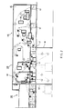
- Figure 1 is a schematic side view of the wire part and the press section of a paper machine viewed from the tending side.
- Figure 2 is a schematic illustration of the wire part and the press section of the paper machine viewed from the driving side.
- Figure 3 is a schematic sectional view of the wet end of the paper machine.
- Figures 4A and 4B are schematic illustrations in part of the construction of an element.
- Fig. 1 is a schematic illustration of the wire part 110 and the press section 120 of a paper machine viewed from the tending side.
- the wire part 110 is provided with a tending-side hood wall 10, which can be shifted in the direction indicated by the arrows S 1 .
- the press section 120 is also provided with a hood wall 20, which can be shifted in the direction indicated by the arrows S 2 .
- the hood construction 10,20 is preferably L-shaped and can be shifted along rails fitted, for example, on the wall at the driving side and on the floor at the tending side. Thus, the hood construction 10,20 forms the ceiling and the vertical wall at the tending side as well as the necessary end walls.
- the portions of the press section 120 placed in the basement 121 are placed inside the hood walls 23.
- the hood wall 20 of the press section 120 is shifted in the direction of the arrow S 2 , for example, onto the hood 30 of the dryer section 130.
- the hood walls 10,20 at the tending side can be provided with transparent portions so as to maintain a sight connection with the paper machine, and with portions that can be opened and closed for servicing, such as lift gates, slide doors, or equivalent.
- Fig. 2 is a schematic illustration of the hood construction on the wire part and on the press section of the paper machine viewed from the driving side.
- the hood wall 45 is continuous and preferably mounted stationarily in its position.
- the hood wall 45 is provided with openable doors 47. Through the hood wall 45, lead-in openings are provided for the drives, frame beams, air ducts, and other equipment. The replacement air is passed into the hood wall 45;10,20 through ducts 44,51,52 preferably connected to the hood wall 45 at the driving side (FIG. 3).
- Fig. 3 is a schematic sectional view in the direction of width of the machine at the wire part 110, and the illustration shows the stationary hood wall 45 at the driving side as well as the L-shaped displaceable hood wall 10 formed at the tending side, which wall 10, thus, forms the ceiling and the other side wall.
- the replacement air into the hood is passed from the duct 44 as the air flow A 1 , and it is distributed into the ducts 51,62 as the air flows A 2 and A 3 , of which the air flow A 2 is blown into the space in the interior of the hood as the flows A 4 through the duct 62 that has been formed in the interior of the fixed hood wall 45, and the flow A 3 is passed from the duct 51 into the duct 52 and further into the duct 62 placed in the interior of the L-shaped hood wall 10, from which it is passed through the blow openings as the flows A 5 . Circulation flow is introduced as the inlet flows A 7 into the interior of the hood through the ducts 64 and 65 as the flows A 6 .
- the hood is sealed in relation to the rest of the machine hall, and the displaceable hood walls 10,20 are sealed in relation to the stationary hood wall 45 and to the floor of the machine hall, for example, by means of brush seals or labyrinth seals (not shown in the illustrations).
- the duct 52 has been made resilient so that displacement of the hood wall 20 does not create problems.
- the temperature of the replacement air is 40...90 °C, preferably 60...70 °C, and its humidity is 5...30 grams of H 2 O per kilogram of dry air, preferably 10...20 grams of H 2 O per kilogram of dry air.
- the temperature of the circulation air is 40...70 °C, preferably 45...55 °C, and its humidity is 50...200 grams of H 2 O per kilogram of dry air, preferably 65...115 grams of H 2 O per kilogram of dry air.
- Fig. 4A is a schematic enlarged illustration in part of an exemplifying embodiment of the construction of the hood wall 10,20,45 in accordance with the invention, in which hood wall there is a continuous sound-insulating and noise-insulating outer wall 61 placed at the side of the machine hall and an inner wall 63 placed inside the hood, between which walls an air duct 62 has been formed, out of which duct 62 the air is passed into the space inside the hood out of slots that have been formed at the joints 67 provided in the inner wall 63.
- separate blow openings 68 have been made into the inner wall 63, through which openings the air is blown into the interior of the hood.
- the exhaust air is evacuated from the interior of the hood through the exhausts provided in the process of the paper machine.
- the inside face of the inner wall 63 of the hood elements 10,20,45 is made of a sheet material, preferably a stainless material, which permits easy cleaning and high strength of the wall 63 face.
- the lower face of the ceiling can be coated with a suitable material, for example teflon, to improve the cleanliness. Since the air flowing in the interior of the wall is preferably heated, condensed water is not formed on said face.
- the outer wall 61 of the wall construction is made of an insulating material and of a sheet material, preferably glass wool and aluminum. The thickness of the entire wall construction is 300...500 mm.
- the hood walls can also be collapsible or of bellows construction or equivalent. Hoods made for small paper machines may consist of ceiling and wall constructions that can be lifted off.
Landscapes
- Paper (AREA)
- Ventilation (AREA)
- Presses And Accessory Devices Thereof (AREA)
- Duct Arrangements (AREA)
- Superstructure Of Vehicle (AREA)
- Closing And Opening Devices For Wings, And Checks For Wings (AREA)
- Percussion Or Vibration Massage (AREA)
Claims (12)
- Haube für ein Siebteil und/oder für eine Pressenpartie in einer Papier-/Kartonmaschine, mit Wänden und einer Decke (10, 20; 45), die eine geschlossene Haube um das Siebteil und/oder die Pressenpartie bilden, wobei eine Klimatisierung in Verbindung mit der Haube eingerichtet ist, dadurch gekennzeichnet, daß die Hauberwände (10, 20; 45) aus äußeren und inneren Wänden (61, 62) zusammengesetzt sind, so daß zwischen diesen sich ein Luftkanal (62) befindet, um einen Austauschluftstrom in das Innere der Haube in Richtung auf einen im wesentlichen mittleren Bereich der Papiermaschine durch Öffnungen (67, 68) zu leiten, die in der inneren Wand (63) eingearbeitet worden sind, wobei die Austauschluft das Innere der Haube im wesentlichen trocken und sauber hält.
- Haube nach Anspruch 1, dadurch gekennzeichnet, daß die Wände (10, 21; 45) der Haube eine vorzugsweise feststehende Vertikalseitenwand an der Antriebsseite und eine wartungsseitige Vertikalseitenwand und eine Decke aufweisen, die als eine Einzelwand gebildet worden sind, die vorzugsweise L-förmig und verschiebbar ist.
- Haube nach Anspruch 1 oder 2, dadurch gekennzeichnet, daß die verschiebbare Haubenwand (10, 20) an der Wartungsseite aus zwei Teilen zusammengesetzt worden ist, so daß die ersten Haubenwand (10) an dem Siebteil (110) und die zweite Haubenwand an der Pressenpartie (120) plaziert ist, wobei die Wände von dem Siebteil und der Pressenpartie weg in entgegengesetzte Richtungen verschiebbar sind.
- Haube nach einem der Ansprüche 1 bis 3, dadurch gekennzeichnet, daß der Strom an Austauschluft in das Innere der Haube derart eingerichtet ist, daß die Haube warm verbleibt, und zwar auch dann, wenn die verschiebbaren Haubenwände sich in der Offenposition befinden.
- Haube nach einem der vorangegangenen Ansprüche, dadurch gekennzeichnet, daß die Temperatur und die Feuchtigkeit der in den Prozeßraum geleiteten Umlaufluft in der Klimatisierung der Haube im Hinblick auf die Temperatur der durch die Papiermaschine verlaufenden Papierbahn zweckmäßig sind.
- Haube nach einem der vorangegangenen Ansprüche, dadurch gekennzeichnet, daß in dem Bereich der Pressenpartie (120) die Haube auch Haubenwände (23) hat, die die in dem Untergeschoßraum plazierten Teile der Pressenpartie umgeben.
- Haube nach einem der vorangegangenen Ansprüche, dadurch gekennzeichnet, daß die Innenfläche der inneren Wand (63) der Haubenwand (10, 20; 45) aus einer Blechmaterial, vorzugsweise aus einem rostfreien Material, angefertigt ist.
- Haube nach einem der vorangegangenen Ansprüche, dadurch gekennzeichnet, daß die äußeren Wand (61) der Haubenwand (10, 20; 45) aus einem Isoliermaterial und einem Blechmaterial, vorzugsweise aus Glaswolle und Aluminium, angefertigt ist.
- Haube nach einem der vorangegangenen Ansprüche, dadurch gekennzeichnet, daß die Haubenwand (10, 20; 45) aus Schichten zusammengesetzt ist, um das Schallisolierungsvermögen der Haubenwand zu verbessern.
- Haube nach einem der vorangegangenen Ansprüche, dadurch gekennzeichnet, daß die Haube relativ zu dem REst der Maschinenhalle mittels einer Bürstdichtung und/oder einer Labyrinthdichtung abgedichtet ist.
- Haube nach einem der vorangegangenen Ansprüche, dadurch gekennzeichnet, daß die Haubenwände (10, 20; 45) mit Tieren versehen sind, die zur Instandhaltung und/oder für mit dem Betrieb in Beziehung stehende Maßnahmen geöffnet und geschlossen werden können.
- Haube nach einem der vorangegangenen Ansprüche, dadurch gekennzeichnet, daß die Haube transpararente Abschnitte in der Haubenwand (10, 20) an der Wartungsseite einschließt, um eine Sichtverbindung mit der Papiermaschine aufrechtzuerhalten.
Applications Claiming Priority (4)
| Application Number | Priority Date | Filing Date | Title |
|---|---|---|---|
| FI952017A FI96329C (fi) | 1995-04-27 | 1995-04-27 | Viira- ja puristinosan huuva |
| FI952017 | 1995-04-27 | ||
| PCT/FI1996/000205 WO1996034145A1 (en) | 1995-04-27 | 1996-04-17 | Hood for a wire part and for a press section |
| US08/638,442 US5666740A (en) | 1995-04-27 | 1996-04-26 | Hood for a wire part and for a press section |
Publications (2)
| Publication Number | Publication Date |
|---|---|
| EP0772710A1 EP0772710A1 (de) | 1997-05-14 |
| EP0772710B1 true EP0772710B1 (de) | 1999-08-11 |
Family
ID=26159952
Family Applications (1)
| Application Number | Title | Priority Date | Filing Date |
|---|---|---|---|
| EP96910056A Expired - Lifetime EP0772710B1 (de) | 1995-04-27 | 1996-04-17 | Haube für eine nass- und presspartie |
Country Status (10)
| Country | Link |
|---|---|
| US (1) | US5666740A (de) |
| EP (1) | EP0772710B1 (de) |
| JP (1) | JP3170288B2 (de) |
| KR (1) | KR100205104B1 (de) |
| AT (1) | ATE183266T1 (de) |
| CA (1) | CA2193701C (de) |
| DE (1) | DE69603684T2 (de) |
| ES (1) | ES2135891T3 (de) |
| FI (1) | FI96329C (de) |
| WO (1) | WO1996034145A1 (de) |
Families Citing this family (7)
| Publication number | Priority date | Publication date | Assignee | Title |
|---|---|---|---|---|
| US6079116A (en) * | 1998-11-06 | 2000-06-27 | Valmet-Karlstad Ab | Duct configuration for a through-air drying apparatus in a papermaking machine |
| DE10026415A1 (de) | 2000-05-29 | 2001-12-06 | Voith Paper Patent Gmbh | Abschirmvorrichtung |
| JP2006207082A (ja) * | 2005-01-31 | 2006-08-10 | Mitsubishi Heavy Ind Ltd | 抄紙機及び抄紙方法 |
| FI118573B (fi) | 2006-06-12 | 2007-12-31 | Metso Paper Inc | Huuva rainanmuodostus-, puristin- ja/tai kuivatusosalle |
| DE102008043989A1 (de) * | 2008-11-21 | 2010-05-27 | Voith Patent Gmbh | Dunsthaube in eine Papier-und/oder Kartonmaschine |
| DE102009046425A1 (de) * | 2009-11-05 | 2011-05-12 | Voith Patent Gmbh | Vorrichtung zur Herstellung einer Materialbahn |
| JP6202735B2 (ja) * | 2013-12-04 | 2017-09-27 | 日本圧着端子製造株式会社 | カードコネクタ |
Family Cites Families (4)
| Publication number | Priority date | Publication date | Assignee | Title |
|---|---|---|---|---|
| US3443325A (en) * | 1966-04-29 | 1969-05-13 | Aer Corp | Exhaust control system for dryer hood |
| SE359874B (de) * | 1966-06-14 | 1973-09-10 | Svenska Flaektfabriken Ab | |
| US3598039A (en) * | 1968-10-04 | 1971-08-10 | Midland Ross Corp | Movable paper machine hood |
| FI63980C (fi) * | 1982-03-18 | 1983-09-12 | Valmet Oy | Foerfarande foer effektivering av luftkonditioneringen i med sluten huv foersedda torkpartier i pappersmaskiner |
-
1995
- 1995-04-27 FI FI952017A patent/FI96329C/fi not_active IP Right Cessation
-
1996
- 1996-04-17 WO PCT/FI1996/000205 patent/WO1996034145A1/en not_active Ceased
- 1996-04-17 DE DE69603684T patent/DE69603684T2/de not_active Expired - Lifetime
- 1996-04-17 EP EP96910056A patent/EP0772710B1/de not_active Expired - Lifetime
- 1996-04-17 AT AT96910056T patent/ATE183266T1/de not_active IP Right Cessation
- 1996-04-17 JP JP53219596A patent/JP3170288B2/ja not_active Expired - Fee Related
- 1996-04-17 CA CA002193701A patent/CA2193701C/en not_active Expired - Fee Related
- 1996-04-17 ES ES96910056T patent/ES2135891T3/es not_active Expired - Lifetime
- 1996-04-26 US US08/638,442 patent/US5666740A/en not_active Expired - Lifetime
- 1996-12-27 KR KR1019960707508A patent/KR100205104B1/ko not_active Expired - Fee Related
Also Published As
| Publication number | Publication date |
|---|---|
| FI952017A0 (fi) | 1995-04-27 |
| CA2193701C (en) | 2000-01-04 |
| JP3170288B2 (ja) | 2001-05-28 |
| ES2135891T3 (es) | 1999-11-01 |
| ATE183266T1 (de) | 1999-08-15 |
| EP0772710A1 (de) | 1997-05-14 |
| DE69603684D1 (de) | 1999-09-16 |
| DE69603684T2 (de) | 2000-03-23 |
| KR100205104B1 (ko) | 1999-06-15 |
| CA2193701A1 (en) | 1996-10-31 |
| FI96329B (fi) | 1996-02-29 |
| KR970704092A (ko) | 1997-08-09 |
| FI96329C (fi) | 1996-06-10 |
| WO1996034145A1 (en) | 1996-10-31 |
| US5666740A (en) | 1997-09-16 |
| JPH09511827A (ja) | 1997-11-25 |
Similar Documents
| Publication | Publication Date | Title |
|---|---|---|
| US5553392A (en) | Process and apparatus for drying sheet materials | |
| CA2136901C (en) | Method in the drying of a paper web as well as dryer sections of a paper machine | |
| EP0772710B1 (de) | Haube für eine nass- und presspartie | |
| US4942674A (en) | Method in the drying of a paper web or equivalent | |
| FI94652C (fi) | Laite rainan sivureunan pitämiseksi paperikoneen kuivaimen huopaa seuraavana | |
| JP3560346B2 (ja) | 乾燥装置および該装置を用いた乾燥部 | |
| EP0870086B1 (de) | Vorrichtung zur trocknung einer faserstoffbahn | |
| US6101735A (en) | Dryer section in a paper machine in which impingement and/or ventilation hoods are used | |
| US4536970A (en) | Procedure for boosting the ventilation in the hood of a paper machine | |
| FI87474C (fi) | Foerfarande och anordning i en pappersmaskin | |
| WO1996032535A1 (en) | Blow device for a dryer section of a paper machine | |
| US5950329A (en) | Method of and apparatus for drying a fiber web | |
| KR20130041811A (ko) | 직물 웨브의 열처리 장치 | |
| EP0653514B1 (de) | Verfahren und Vorrichtung zur Trocknung von bahnförmigem Material | |
| NZ210559A (en) | Air curtain:preventing vortices | |
| JP3007529B2 (ja) | シート状物質の乾燥方法及び装置 | |
| FI118573B (fi) | Huuva rainanmuodostus-, puristin- ja/tai kuivatusosalle | |
| US5594996A (en) | Apparatus for drying a fibre web | |
| CA2026045A1 (en) | Method for contact-free drying of a paper or board web | |
| CA2152834C (en) | Arrangement for lowering the noise level of a cooling layer in a pulp dryer and a pulp dryer | |
| FI83551C (fi) | Pressparti i pappersmaskin. | |
| EP1012386B1 (de) | Verfahren zur optimierung von verdampfungstrocknung von papier, geschwindigkeit , und papierqualität sowie eine trockenpartie einer papiermaschine zur durchführung des verfahrens | |
| KR200178523Y1 (ko) | 피혁지용 건조장치 | |
| JP3007542B2 (ja) | シート状物質の乾燥方法及び装置 | |
| US3452446A (en) | Apparatus for the ventilation of a paper machine |
Legal Events
| Date | Code | Title | Description |
|---|---|---|---|
| PUAI | Public reference made under article 153(3) epc to a published international application that has entered the european phase |
Free format text: ORIGINAL CODE: 0009012 |
|
| 17P | Request for examination filed |
Effective date: 19961218 |
|
| AK | Designated contracting states |
Kind code of ref document: A1 Designated state(s): AT DE ES FR GB IT SE |
|
| GRAG | Despatch of communication of intention to grant |
Free format text: ORIGINAL CODE: EPIDOS AGRA |
|
| 17Q | First examination report despatched |
Effective date: 19981106 |
|
| GRAG | Despatch of communication of intention to grant |
Free format text: ORIGINAL CODE: EPIDOS AGRA |
|
| GRAH | Despatch of communication of intention to grant a patent |
Free format text: ORIGINAL CODE: EPIDOS IGRA |
|
| GRAH | Despatch of communication of intention to grant a patent |
Free format text: ORIGINAL CODE: EPIDOS IGRA |
|
| GRAA | (expected) grant |
Free format text: ORIGINAL CODE: 0009210 |
|
| AK | Designated contracting states |
Kind code of ref document: B1 Designated state(s): AT DE ES FR GB IT SE |
|
| REF | Corresponds to: |
Ref document number: 183266 Country of ref document: AT Date of ref document: 19990815 Kind code of ref document: T |
|
| REF | Corresponds to: |
Ref document number: 69603684 Country of ref document: DE Date of ref document: 19990916 |
|
| REG | Reference to a national code |
Ref country code: ES Ref legal event code: FG2A Ref document number: 2135891 Country of ref document: ES Kind code of ref document: T3 |
|
| ITF | It: translation for a ep patent filed | ||
| ET | Fr: translation filed | ||
| PLBE | No opposition filed within time limit |
Free format text: ORIGINAL CODE: 0009261 |
|
| STAA | Information on the status of an ep patent application or granted ep patent |
Free format text: STATUS: NO OPPOSITION FILED WITHIN TIME LIMIT |
|
| 26N | No opposition filed | ||
| REG | Reference to a national code |
Ref country code: GB Ref legal event code: IF02 |
|
| PGFP | Annual fee paid to national office [announced via postgrant information from national office to epo] |
Ref country code: ES Payment date: 20080429 Year of fee payment: 13 |
|
| PGFP | Annual fee paid to national office [announced via postgrant information from national office to epo] |
Ref country code: IT Payment date: 20080426 Year of fee payment: 13 |
|
| PGFP | Annual fee paid to national office [announced via postgrant information from national office to epo] |
Ref country code: SE Payment date: 20080414 Year of fee payment: 13 |
|
| PGFP | Annual fee paid to national office [announced via postgrant information from national office to epo] |
Ref country code: FR Payment date: 20080412 Year of fee payment: 13 |
|
| PGFP | Annual fee paid to national office [announced via postgrant information from national office to epo] |
Ref country code: GB Payment date: 20080421 Year of fee payment: 13 |
|
| EUG | Se: european patent has lapsed | ||
| GBPC | Gb: european patent ceased through non-payment of renewal fee |
Effective date: 20090417 |
|
| REG | Reference to a national code |
Ref country code: FR Ref legal event code: ST Effective date: 20091231 |
|
| PG25 | Lapsed in a contracting state [announced via postgrant information from national office to epo] |
Ref country code: GB Free format text: LAPSE BECAUSE OF NON-PAYMENT OF DUE FEES Effective date: 20090417 Ref country code: FR Free format text: LAPSE BECAUSE OF NON-PAYMENT OF DUE FEES Effective date: 20091222 |
|
| REG | Reference to a national code |
Ref country code: ES Ref legal event code: FD2A Effective date: 20090418 |
|
| PG25 | Lapsed in a contracting state [announced via postgrant information from national office to epo] |
Ref country code: ES Free format text: LAPSE BECAUSE OF NON-PAYMENT OF DUE FEES Effective date: 20090418 |
|
| PGFP | Annual fee paid to national office [announced via postgrant information from national office to epo] |
Ref country code: DE Payment date: 20100423 Year of fee payment: 15 Ref country code: AT Payment date: 20100415 Year of fee payment: 15 |
|
| PG25 | Lapsed in a contracting state [announced via postgrant information from national office to epo] |
Ref country code: IT Free format text: LAPSE BECAUSE OF NON-PAYMENT OF DUE FEES Effective date: 20090417 |
|
| PG25 | Lapsed in a contracting state [announced via postgrant information from national office to epo] |
Ref country code: SE Free format text: LAPSE BECAUSE OF NON-PAYMENT OF DUE FEES Effective date: 20090418 |
|
| REG | Reference to a national code |
Ref country code: DE Ref legal event code: R119 Ref document number: 69603684 Country of ref document: DE |
|
| REG | Reference to a national code |
Ref country code: DE Ref legal event code: R119 Ref document number: 69603684 Country of ref document: DE |
|
| REG | Reference to a national code |
Ref country code: AT Ref legal event code: MM01 Ref document number: 183266 Country of ref document: AT Kind code of ref document: T Effective date: 20110417 |
|
| PG25 | Lapsed in a contracting state [announced via postgrant information from national office to epo] |
Ref country code: AT Free format text: LAPSE BECAUSE OF NON-PAYMENT OF DUE FEES Effective date: 20110417 |
|
| PG25 | Lapsed in a contracting state [announced via postgrant information from national office to epo] |
Ref country code: DE Free format text: LAPSE BECAUSE OF NON-PAYMENT OF DUE FEES Effective date: 20111031 |