EP0772300B1 - Verfahren zur Umwandlung von, insbesondere zueinander amplitudendifferenten, EIN/AUS-Analogsignalen in entsprechende EIN/AUS-Digitalsignale - Google Patents
Verfahren zur Umwandlung von, insbesondere zueinander amplitudendifferenten, EIN/AUS-Analogsignalen in entsprechende EIN/AUS-Digitalsignale Download PDFInfo
- Publication number
- EP0772300B1 EP0772300B1 EP96116721A EP96116721A EP0772300B1 EP 0772300 B1 EP0772300 B1 EP 0772300B1 EP 96116721 A EP96116721 A EP 96116721A EP 96116721 A EP96116721 A EP 96116721A EP 0772300 B1 EP0772300 B1 EP 0772300B1
- Authority
- EP
- European Patent Office
- Prior art keywords
- threshold value
- analog signals
- reference threshold
- ref
- signal
- Prior art date
- Legal status (The legal status is an assumption and is not a legal conclusion. Google has not performed a legal analysis and makes no representation as to the accuracy of the status listed.)
- Expired - Lifetime
Links
- 238000000034 method Methods 0.000 title claims description 27
- 238000012544 monitoring process Methods 0.000 claims description 11
- 230000004888 barrier function Effects 0.000 claims description 3
- 230000002123 temporal effect Effects 0.000 claims description 3
- 230000010354 integration Effects 0.000 claims description 2
- 238000010411 cooking Methods 0.000 claims 1
- 238000001514 detection method Methods 0.000 description 6
- 238000009434 installation Methods 0.000 description 6
- 230000032683 aging Effects 0.000 description 5
- 230000006399 behavior Effects 0.000 description 3
- 238000011156 evaluation Methods 0.000 description 3
- 230000006870 function Effects 0.000 description 3
- 238000009826 distribution Methods 0.000 description 2
- 239000011521 glass Substances 0.000 description 2
- 230000005693 optoelectronics Effects 0.000 description 2
- 230000011514 reflex Effects 0.000 description 2
- 230000006978 adaptation Effects 0.000 description 1
- 239000000919 ceramic Substances 0.000 description 1
- 238000006243 chemical reaction Methods 0.000 description 1
- 238000005352 clarification Methods 0.000 description 1
- 238000010438 heat treatment Methods 0.000 description 1
- 230000002452 interceptive effect Effects 0.000 description 1
- 230000005389 magnetism Effects 0.000 description 1
- 238000004519 manufacturing process Methods 0.000 description 1
- 230000002265 prevention Effects 0.000 description 1
- 230000002035 prolonged effect Effects 0.000 description 1
- 238000003860 storage Methods 0.000 description 1
Images


Classifications
-
- H—ELECTRICITY
- H03—ELECTRONIC CIRCUITRY
- H03K—PULSE TECHNIQUE
- H03K17/00—Electronic switching or gating, i.e. not by contact-making and –breaking
- H03K17/94—Electronic switching or gating, i.e. not by contact-making and –breaking characterised by the way in which the control signals are generated
- H03K17/96—Touch switches
- H03K17/9627—Optical touch switches
- H03K17/9631—Optical touch switches using a light source as part of the switch
-
- H—ELECTRICITY
- H05—ELECTRIC TECHNIQUES NOT OTHERWISE PROVIDED FOR
- H05B—ELECTRIC HEATING; ELECTRIC LIGHT SOURCES NOT OTHERWISE PROVIDED FOR; CIRCUIT ARRANGEMENTS FOR ELECTRIC LIGHT SOURCES, IN GENERAL
- H05B3/00—Ohmic-resistance heating
- H05B3/68—Heating arrangements specially adapted for cooking plates or analogous hot-plates
- H05B3/74—Non-metallic plates, e.g. vitroceramic, ceramic or glassceramic hobs, also including power or control circuits
Definitions
- the invention relates to a method of conversion of, in particular amplitude-different, on / off analog signals into corresponding ON / OFF digital signals according to Claim 1.
- a preferred practical application example can operate an electronic hob control be seen with multiple actuators in the form of key elements made of touch-sensitive Infrared reflex light barriers exist when present a minimum reflection an ON analog signal and an OFF analog signal if there is no minimum reflection submit, which then as a processed digital output signal "ON” or "OFF” output signal in a controller for control the hotplates.
- the control method described above presupposes that the fixed thresholds given to the comparator in each Case within the signal swing of the ON analog signals or the OFF analog signals are and are known.
- From DE 26 58 080 A is a pulse regenerator for generating defined pulses from with Interfering signals are known, using a differential amplifier as a comparator and breakover voltage generator and a network in front of the differential amplifier Prevention of input overload is provided.
- From US 4 433 256 A is a limiting circuit or a zero crossing detector known to convert an analog input waveform into a binary digital waveform convert so that it is suitable for a signal processor.
- a sensor signal processing unit is known from EP 0 621 460 A1, in particular for detecting magnetism as an electrical signal and digitizing it Signal.
- the sensor signal processing unit has a tip holding device Maintaining the peak value of the output signals from the sensor, one Depth holding device for holding the lowest value of the output signals from the sensor, a threshold value setting device for setting the threshold value from the peak value and the lowest value and a comparison device for comparing the output signal of the sensor with the threshold value and for outputting a binary signal in Agreement with their difference.
- Actuator with mutual guarantee S / N ratio of the reference threshold values and due to the tracking dependency of these reference thresholds from those due to above-mentioned influences may change absolute Values of the ON / OFF analog signals is a relative detection and evaluation and the automatic adjustment of the detection limits guaranteed in such a way that influences such as component variation, Temperature influences, aging, mechanical installation tolerances as well as fluctuations caused by different Handling the actuators for dispensing of the analog signals result in the manner of a learning function can be automatically compensated or eliminated; is expedient in the sense of a desired targeted Inertia provided that the first reference threshold or the second reference threshold within each a threshold range with an upper and a lower range limit and thus the previously described Tracking of detection limits due to changes due to interference only becomes effective when recognized is that the analog signals tend towards shift one or the other area boundary.
- At least the OFF reference threshold values or the range limits the associated threshold value ranges before first use once in an initialization process the maximum and minimum values, in particular amplitudes, of previously detected OFF analog signals from each actuator set.
- At least the analog ones Signals, especially pulse-wise voltage amplitudes, which correspond to the states "OFF" are read into a memory and filed there. These read values then serve as the basis for the first definition of these signals assigned reference threshold values or range limits the threshold value ranges and thus set the conditions forth, which correspond to the later operating conditions.
- the ON reference threshold values or the associated threshold value ranges when starting for the first time Define the previously defined OFF reference threshold in a fixed and for all signal transmitters an actuator the same signal-to-noise ratio a be the empirical value of the component or installation tolerances won. An optimal individual adjustment then takes place as part of the subsequent operational Tracking that both for the OFF analog signals as also takes place independently of one another for the ON analog signals. It is important to ensure that both the condition "ON" as well as the state "OFF" of 0 different signal values correspond.
- FIG. 1 shows the basic structure of an optoelectronic hotplate controller with a touch-sensitive infrared reflex light barrier; this is done by an electronic controller C via a transmitter control SA, a transmitter S, in particular an infrared light emitting diode operating in pulse mode (IR-LED) controlled cyclically.
- the infrared light pulses of the Transmitter S hit a glass surface R, in particular the ceramic surface a hotplate, and are operated by this when not in use
- Touch sensor essentially only as a scattered light reflection beam R2 due to an internal reflection a receiver E, in particular an infrared receiver, with a subsequent receiver circuit EB reflected. Only when the outer contact surface of the glass surface R is targeted, e.g. covered by placing an operating finger , there is a useful light reflection beam R1, which the amplitude of the scattered light signal exceeds such that in a comparator K, which is conveniently in the electronic Unit of the controller C is integrated, a ON analog signal is identifiable.
- FIGS. 2, 3 qualitatively show the course of the comparator K received analog input voltage of a pulse when actuated one of the key elements T1-T6 of the electronic hob control.
- Such as. clarified with reference to FIG 2, must to recognize the state "ON" when the respective one is actuated Key element T1-T6 exceeded a signal level EINmin and to recognize the state "OFF” after releasing the Actuation of the button element falls below a signal level AUSmax become. This sets a hysteresis which defines the switching behavior of the key element.
- FIG 3 shows the qualitative course assumed in FIG the analog input voltage and those previously described Detection limits the definition of a reference threshold ON-Ref and a reference threshold value AUS-Ref and corresponding threshold value ranges, each with an upper one Range limit EINmax or AUSmax and a lower threshold value limit ONmin or OFFmin.
- FIG. 4 shows the example of a distribution due to tolerance different reference threshold values or threshold value ranges distributed over six key elements T1-T6 of an electronic Heating element controller.
- the aforementioned reference threshold values or threshold value ranges with an upper and a lower range limit are for each individual key element T1-T6 before first use once by reading, evaluating and then Storage of the ON / OFF analog signals as a reference determined individually in the controller C. It will - how 4 can be seen - in each case between the lower range limit of the upper ON threshold range and upper range limit of the lower OFF threshold range a minimum signal-to-noise ratio (a1-a6) is ensured.
- the differences in the corresponding analog voltage signals in particular due to component tolerances the infrared transmitter or infrared receiver used as well their installation tolerances, e.g. the beam strength of the transmitter can influence.
- the initialization can - if e.g. Empirical values for these tolerances exist - are simplified by the fact that the ON reference values are not separated by reading the ON analog signals determined but only in experience-related uniform distance to each by processing of OFF analog signals previously read in for the first time OFF reference value be determined.
- One for each key element T1-T6 Distance can then be determined in the subsequent automatic tracking for each key element.
- control and measuring effort is further reduced according to one embodiment of the invention, all of different key elements T1-T6 and each delivered to different receivers E or transmitters S.
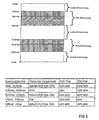
- FIG. 6 shows, for clarification, starting from for a single one Button assignment to defined threshold value ranges of different voltage signal values on the input side of a key element for a respective status of this key element and to an associated "OFF" filter or "ON” filter in which the incoming at the monitoring intervals ON analog signals or OFF analog signals read have been.
Landscapes
- Chemical & Material Sciences (AREA)
- Engineering & Computer Science (AREA)
- Ceramic Engineering (AREA)
- Electronic Switches (AREA)
Description
- FIG 1
- den grundsätzlichen Aufbau einer elektronischen Kochstellensteuerung;
- FIG 2
- ein einzelnes pulsförmiges EIN/AUS-Analogsignal mit Referenzschwellwerten für "EIN" bzw."AUS";
- FIG 3
- ein einzelnes pulsförmiges EIN/AUS-Analogsignal mit jeweils einem EIN-Referenzschwellwert und einem AUS-Referenzschwellwert und mit einem diesen jeweils mit einer oberen Bereichsgrenze und einer unteren Bereichsgrenze übergreifenden Schwellwertbereich;
- FIG 4
- die beispielhafte Verteilung von Referenzschwellwerten bzw. Schwellwertbereichen für sechs Tastenelemente eines Tastenfeldes einer elektronischen Kochstellensteuerung;
- FIG 5
- den Ablauf einer Auswertung eines EIN/AUS-Analogsignals im Sinne einer Nachführung der Referenzschwellwerte an eine tendenzielle, z.B. alterungsbedingte, Änderung der Amplituden der Analogsignale;
- FIG 6
- den Zusammenhang zwischen dem jeweiligen Status eines Tastenelementes mit jeweils entsprechendem Spannungs-Analogeingangssignal einerseits und einer Zuordnung zu einem "EIN"-Filter bzw. zu einem "AUS"-Filter.
Claims (12)
- Verfahren zur Umwandlung von, insbesondere zueinander amplitudendifferenten, EIN/AUS-Analogsignalen in entsprechende EIN/AUS-Digitalsignale bei Erreichen eines jeweils spezifischen, einem Komparator (K) vorgebbaren EIN-Referenzschwellwertes oder AUS-Referenzschwellwertes, insbesondere eines jeweiligen Amplituden-Referenzschwellwertes, mit folgenden Merkmalen:a) Dem Komparator (K) wird für die EIN-Analogsignale eines Signalgebers ein erster, ein EIN-Analogsignal erkennender Referenzschwellwert (EIN-Ref) zugeordnet;b) dem Komparator (K) wird für die AUS-Analogsignale eines Signalgebers ein zweiter, ein AUS-Analogsignal erkennender, insbesondere gegenüber dem ersten pegelniedrigerer, Referenzschwellwert (AUS-Ref) zugeordnet;c) der erste Referenzschwellwert (EIN-Ref) ist in Nachführabhängigkeit von den absoluten Werten, insbesondere Amplitudenwerten, des jeweiligen EIN-Analogsignals gestellt;d) der zweite Referenzschwellwert (AUS-Ref) ist in Nachführabhängigkeit von den absoluten Werten, insbesondere Amplitudenwerten, des jeweiligen AUS-Analogsignals in Nachführbarabhängigkeit gestellt;e) der erste Referenzschwellwert (EIN-Ref) wird im Sinne eines gewährleisteten Störabstandes (a) von dem zweiten Referenzschwellwert (AUS-Ref) beabstandet;f) der erste Referenzschwellwert (EIN-Ref) und der zweite Referenzschwellwert (AUS-Ref) liegt jeweils innerhalb eines Schwellwertbereiches mit einer oberen und einer unteren Bereichsgrenze (EINmax;ElNmin; AUSmax;AUSmin);j) die Nachführung der Referenzschwellwerte und/oder der Schwellwertbereiche erfolgt aufgrund eines sukzessiven Vergleiches von nach einem erstmaligen Initialisierungsvorgang in festlegbaren zeitlichen Überwachungsabständen jeweils erfassten EIN-Analogsignalen und AUS-Analogsignalen.
- Verfahren nach Anspruch 1 mit dem Merkmal:g) Zumindest der zweite Referenzschwellwert (AUS-Ref) und/oder die Bereichsgrenzen des zugehörigen Schwellwertbereiches werden in dem Initialisierungsvorgang aufgrund der maximalen und minimalen Werte, insbesondere Amplituden, von zuvor erfassten AUS-Analogsignalen festegelegt.
- Verfahren nach Anspruch 2 mit dem Merkmal:h) Der erste Referenzschwellwert (EIN-Ref) und/oder die Bereichsgrenzen des zugehörigen Schwellwertbereiches werden in einem definierten Störabstand (a) zu dem zweiten Referenzschwellwerte (AUS-Ref) und/oder dem zugehörigen Schwellwertbereich festgelegt.
- Verfahren nach Anspruch 2 mit dem Merkmal:i) Der erste Referenzschwellwert (EIN-Ref)und der zweite Referenzschwellwert (AUS-Ref) und/oder die Bereichsgrenzen der jeweiligen Schwellwertbereiche werden in dem Initialisierungsvorgang jeweils aufgrund der maximalen und minimalen Werte, insbesondere Amplituden, von zuvor erfassten EIN-Analogsignalen und AUS-Analogsignalen festgelegt.
- Verfahren nach einem der vorhergehenden Ansprüche mit dem Merkmal:k) Die, insbesondere pulsförmigen, EIN-Analogsignale und AUS-Analogsignale werden während der zeitlichen Überwachungsabstände im Sinne einer zeitlichen Integration in einen Speicher eingelesen.
- Verfahren nach Anspruch 5 mit dem Merkmal:I) Den EIN-Analogsignalen und/oder den AUS-Analogsignalen ist jeweils ein spezifischer Filter, insbesondere Amplitudenfilter, im Sinne eines jeweils abgestimmten Tiefpasses zugeordnet.
- Verfahren nach Anspruch 6 mit dem Merkmal:m) Die Nachführung erfolgt aufgrund des Überschreitens einer festlegbaren Mindestdifferenz zwischen den Referenzschwellwerten und/oder den Schwellwertbereichen aufeinanderfolgender Überwachungsabstände.
- Verfahren nach Anspruch 7 mit dem Merkmal:n) Bei der Berechnung der Mindestdifferenz bleiben Analogsignale, insbesondere Amplituden, die im Überwachungszeitraum außerhalb des jeweiligen zugehörigen Referenzschwellwertes und/oder Schwellwertbereiches liegen, unberücksichtigt.
- Verfahren nach zumindest einem der vorhergehenden Ansprüche mit den Merkmalen:o) Eine Betätigungsvorrichtung enthält mehrere Signalgeber mit jeweils individuellen EIN/AUS-Analogsignalen;p) den EIN-Analogsignalen und/oder AUS-Analogsignalen eines jeden Signalgebers ist je ein erster Referenzschwellwert (EIN-Ref) und je ein zweiter Referenzschwellwert (AUS-Ref) und/oder je ein entsprechender Schwellwertbereich zugeordnet.
- Verfahren nach Anspruch 3 oder 9 mit dem Merkmal:q) Die ersten Referenzschwellwerte (EIN-Ref) sämtlicher Signalgeber werden bei dem Initialisierungsvorgang mit dem gleichen Störabstand zu dem je Signalgeber individuell ermittelten zweiten Referenzschwellwert (AUS-Ref) beabstandet.
- Verfahren nach einem der vorhergehenden Ansprüche mit dem Merkmal:r) Mehrere, jeweils von verschiedenen Empfängem und/oder Gebern gelieferte Ein/Aus-Analogsignale sind einem einzigen Komparator (K) zugeordnet;s) die verschiedenen Signalgeber werden sukzessiv, insbesondere zyklisch, in Überwachungsabhängigkeit mit dem Komparator (K) gestellt.
- Verfahren nach einem der vorhergehenden Ansprüche mit dem Merkmal:t) Die Ein-Analogsignale und Aus-Analogsignale werden jeweils von Signalgebern einer Kochstellensteuerung eines Herdes, insbesondere von je einem mehrerer Tastenelemente (T1-T6) mit je einer berührungsempfindlichen infrarot-Reflexlichtschranke, abgegeben.
Applications Claiming Priority (2)
| Application Number | Priority Date | Filing Date | Title |
|---|---|---|---|
| DE19540835 | 1995-10-30 | ||
| DE19540835A DE19540835C1 (de) | 1995-10-30 | 1995-10-30 | Verfahren zur Umwandlung von, insbesondere zueinander amplitudendifferenten, EIN/AUS-Analogsignalen in entsprechende EIN/AUS-Digitalsignale |
Publications (3)
| Publication Number | Publication Date |
|---|---|
| EP0772300A2 EP0772300A2 (de) | 1997-05-07 |
| EP0772300A3 EP0772300A3 (de) | 1998-03-25 |
| EP0772300B1 true EP0772300B1 (de) | 2004-08-11 |
Family
ID=7776443
Family Applications (1)
| Application Number | Title | Priority Date | Filing Date |
|---|---|---|---|
| EP96116721A Expired - Lifetime EP0772300B1 (de) | 1995-10-30 | 1996-10-17 | Verfahren zur Umwandlung von, insbesondere zueinander amplitudendifferenten, EIN/AUS-Analogsignalen in entsprechende EIN/AUS-Digitalsignale |
Country Status (2)
| Country | Link |
|---|---|
| EP (1) | EP0772300B1 (de) |
| DE (2) | DE19540835C1 (de) |
Families Citing this family (4)
| Publication number | Priority date | Publication date | Assignee | Title |
|---|---|---|---|---|
| DE10007752A1 (de) * | 2000-02-19 | 2001-08-23 | Braun Gmbh | Verfahren zur Anpassung eines Entscheidungspegels bei der Umwandlung eines analogen Signals in ein digitales Signal und digitaler Empfänger |
| DE10159336B4 (de) * | 2001-05-24 | 2004-08-05 | Sie Elektronik Industrie-Elektronik Gmbh | Verfahren zur Selbstjustierung eines Sensors sowie selbstjustierender Sensor |
| US9362907B2 (en) * | 2010-12-01 | 2016-06-07 | Htc Corporation | Method of dynamically adjusting threshold values and related electronic device |
| DE102011081487B4 (de) * | 2011-08-24 | 2023-12-14 | Endress + Hauser Flowtec Ag | Optoelektronisches Bedienelement sowie Feldgerät der Prozessautomatisierungstechnik mit einem solchen optoelektronischen Bedienelement |
Citations (3)
| Publication number | Priority date | Publication date | Assignee | Title |
|---|---|---|---|---|
| DE2658080A1 (de) * | 1976-12-22 | 1978-07-06 | Kloeckner Humboldt Deutz Ag | Impulsregenerator |
| US4433256A (en) * | 1982-07-06 | 1984-02-21 | Motorola, Inc. | Limiter with dynamic hysteresis |
| EP0621460A1 (de) * | 1993-04-15 | 1994-10-26 | Nippondenso Co., Ltd. | Ausgangssignalverarbeitungseinheit für einen Sensor |
Family Cites Families (4)
| Publication number | Priority date | Publication date | Assignee | Title |
|---|---|---|---|---|
| DE3408261A1 (de) * | 1984-03-07 | 1985-09-19 | Hansa Metallwerke Ag, 7000 Stuttgart | Annaeherungsschalter sowie steuerschaltungsanordnung hierfuer |
| FR2686147A1 (fr) * | 1992-01-09 | 1993-07-16 | Dietrich Europ Electromenager | Detecteur a touche optique pour la commande d'un des foyers d'une table de cuisson dite vitro-ceramique. |
| DE4207772C3 (de) * | 1992-03-11 | 1999-01-21 | Cherry Mikroschalter Gmbh | Sensorschalter mit Größenerkennung |
| DE4214300C1 (en) * | 1992-04-30 | 1993-06-17 | Wsp Ingenieurgesellschaft Fuer Waermetechnik, Stroemungstechnik Und Prozesstechnik Mbh, 5100 Aachen, De | Hysteresis reduction method for inductive or capacitive proximity switch - disconnects operating voltage when detected object lies within response range of switch sensor to prevent hysteresis |
-
1995
- 1995-10-30 DE DE19540835A patent/DE19540835C1/de not_active Expired - Fee Related
-
1996
- 1996-10-17 DE DE59611056T patent/DE59611056D1/de not_active Expired - Fee Related
- 1996-10-17 EP EP96116721A patent/EP0772300B1/de not_active Expired - Lifetime
Patent Citations (3)
| Publication number | Priority date | Publication date | Assignee | Title |
|---|---|---|---|---|
| DE2658080A1 (de) * | 1976-12-22 | 1978-07-06 | Kloeckner Humboldt Deutz Ag | Impulsregenerator |
| US4433256A (en) * | 1982-07-06 | 1984-02-21 | Motorola, Inc. | Limiter with dynamic hysteresis |
| EP0621460A1 (de) * | 1993-04-15 | 1994-10-26 | Nippondenso Co., Ltd. | Ausgangssignalverarbeitungseinheit für einen Sensor |
Also Published As
| Publication number | Publication date |
|---|---|
| EP0772300A3 (de) | 1998-03-25 |
| DE59611056D1 (de) | 2004-09-16 |
| EP0772300A2 (de) | 1997-05-07 |
| DE19540835C1 (de) | 1996-08-22 |
Similar Documents
| Publication | Publication Date | Title |
|---|---|---|
| EP2942644B1 (de) | Entfernungsmessender sensor und verfahren zur erfassung und abstandsbestimmung von objekten | |
| EP0443141B1 (de) | Schaltungsanordnung zur Steuerung eines Lüfters | |
| EP0623829B1 (de) | Verfahren und Vorrichtung zur Sendestromregelung bei Sensoranordnungen | |
| DE102007005187A1 (de) | Verfahren und Vorrichtung zur Bestimmung einer Entfernung zu einem rückstrahlenden Objekt | |
| EP1972961A2 (de) | Optoelektronischer Sensor und Verfahren zur Messung einer Entfernung oder einer Entfernungsänderung | |
| DE10355008A1 (de) | Verfahren zur Verarbeitung eines Empfangssignals und optischer Sensor | |
| EP0312524A1 (de) | Verfahren und vorrichtung zur entfernungsmessung durch verarbeitung optischer impulssignale. | |
| CH668338A5 (de) | Annaeherungsschalter mit einer steuerschaltung. | |
| EP1125406B1 (de) | Verfahren und vorrichtung zum aufbereiten eines empfangenen signals, das daten codiert übermittelt | |
| DE68908449T2 (de) | Elektronische Methoden und Schaltungen zur drahtgebundenen Fernabfrage von elektrischen Empfänger. | |
| DE19540835C1 (de) | Verfahren zur Umwandlung von, insbesondere zueinander amplitudendifferenten, EIN/AUS-Analogsignalen in entsprechende EIN/AUS-Digitalsignale | |
| EP0847345B1 (de) | Vorrichtung zum erfassen einer benetzung einer scheibe | |
| EP0768545B1 (de) | Verfahren zum Betrieb eines optischen Lichttasters | |
| DE3207993A1 (de) | Zweiweg-gegenverkehrs-feuermelder | |
| EP0039799B1 (de) | Vorrichtung zum Erfassen von Bewegungen | |
| DE19917487B4 (de) | Optoelektronische Vorrichtung | |
| EP0898368A2 (de) | Sensoreinrichtung | |
| EP3834001B1 (de) | Vorrichtung zur abstandsabhängigen erkennung eines mobilen objektes sowie verfahren zu deren betrieb | |
| DE19547300C1 (de) | Betätigungsvorrichtung mit zumindest einem optoelektronischen Tastenelement | |
| DE19948892C2 (de) | Impulsdetektor und Verfahren zur Detektion von sinusförmigen Impulsen | |
| EP0780979A2 (de) | Betätigungsvorrichtung mit zumindest einem optoelektronischen Tastenelement | |
| DE102022203146A1 (de) | Sensoreinheit und Verfahren für die Detektion eines in einem Sensorbereich der Sensoreinheit vorhandenen Objekts mit verschiedenen Sensormodi | |
| DE19832673C2 (de) | Optischer Lichttaster | |
| DE102022203143A1 (de) | Sensoreinheit und Verfahren für die Detektion eines einen Sensorbereich der Sensoreinheit passierenden Objekts | |
| DE102022203145B4 (de) | Sensoreinheit und Verfahren für die Detektion eines in einem Sensorbereich der Sensoreinheit vorhandenen Objekts mit Stromregelung |
Legal Events
| Date | Code | Title | Description |
|---|---|---|---|
| PUAI | Public reference made under article 153(3) epc to a published international application that has entered the european phase |
Free format text: ORIGINAL CODE: 0009012 |
|
| AK | Designated contracting states |
Kind code of ref document: A2 Designated state(s): DE FR GB IT |
|
| PUAL | Search report despatched |
Free format text: ORIGINAL CODE: 0009013 |
|
| AK | Designated contracting states |
Kind code of ref document: A3 Designated state(s): DE FR GB IT |
|
| 17P | Request for examination filed |
Effective date: 19980819 |
|
| RAP1 | Party data changed (applicant data changed or rights of an application transferred) |
Owner name: BSH BOSCH UND SIEMENS HAUSGERAETE GMBH |
|
| 17Q | First examination report despatched |
Effective date: 20030203 |
|
| GRAP | Despatch of communication of intention to grant a patent |
Free format text: ORIGINAL CODE: EPIDOSNIGR1 |
|
| RAP1 | Party data changed (applicant data changed or rights of an application transferred) |
Owner name: BSH BOSCH UND SIEMENS HAUSGERAETE GMBH |
|
| GRAA | (expected) grant |
Free format text: ORIGINAL CODE: 0009210 |
|
| GRAS | Grant fee paid |
Free format text: ORIGINAL CODE: EPIDOSNIGR3 |
|
| AK | Designated contracting states |
Kind code of ref document: B1 Designated state(s): DE FR GB IT |
|
| REG | Reference to a national code |
Ref country code: GB Ref legal event code: FG4D Free format text: NOT ENGLISH |
|
| REF | Corresponds to: |
Ref document number: 59611056 Country of ref document: DE Date of ref document: 20040916 Kind code of ref document: P |
|
| GBT | Gb: translation of ep patent filed (gb section 77(6)(a)/1977) | ||
| ET | Fr: translation filed | ||
| PLBE | No opposition filed within time limit |
Free format text: ORIGINAL CODE: 0009261 |
|
| STAA | Information on the status of an ep patent application or granted ep patent |
Free format text: STATUS: NO OPPOSITION FILED WITHIN TIME LIMIT |
|
| 26N | No opposition filed |
Effective date: 20050512 |
|
| PGFP | Annual fee paid to national office [announced via postgrant information from national office to epo] |
Ref country code: GB Payment date: 20061024 Year of fee payment: 11 |
|
| PGFP | Annual fee paid to national office [announced via postgrant information from national office to epo] |
Ref country code: IT Payment date: 20061031 Year of fee payment: 11 Ref country code: DE Payment date: 20061031 Year of fee payment: 11 |
|
| GBPC | Gb: european patent ceased through non-payment of renewal fee |
Effective date: 20071017 |
|
| PG25 | Lapsed in a contracting state [announced via postgrant information from national office to epo] |
Ref country code: DE Free format text: LAPSE BECAUSE OF NON-PAYMENT OF DUE FEES Effective date: 20080501 |
|
| REG | Reference to a national code |
Ref country code: FR Ref legal event code: ST Effective date: 20080630 |
|
| PGFP | Annual fee paid to national office [announced via postgrant information from national office to epo] |
Ref country code: FR Payment date: 20061020 Year of fee payment: 11 |
|
| PG25 | Lapsed in a contracting state [announced via postgrant information from national office to epo] |
Ref country code: GB Free format text: LAPSE BECAUSE OF NON-PAYMENT OF DUE FEES Effective date: 20071017 |
|
| PG25 | Lapsed in a contracting state [announced via postgrant information from national office to epo] |
Ref country code: FR Free format text: LAPSE BECAUSE OF NON-PAYMENT OF DUE FEES Effective date: 20071031 |
|
| PG25 | Lapsed in a contracting state [announced via postgrant information from national office to epo] |
Ref country code: IT Free format text: LAPSE BECAUSE OF NON-PAYMENT OF DUE FEES Effective date: 20071017 |