EP0771963B1 - Synchronring mit Ringfeder - Google Patents
Synchronring mit Ringfeder Download PDFInfo
- Publication number
- EP0771963B1 EP0771963B1 EP96890142A EP96890142A EP0771963B1 EP 0771963 B1 EP0771963 B1 EP 0771963B1 EP 96890142 A EP96890142 A EP 96890142A EP 96890142 A EP96890142 A EP 96890142A EP 0771963 B1 EP0771963 B1 EP 0771963B1
- Authority
- EP
- European Patent Office
- Prior art keywords
- synchronizing ring
- annular spring
- ring
- abutment
- abutment elements
- Prior art date
- Legal status (The legal status is an assumption and is not a legal conclusion. Google has not performed a legal analysis and makes no representation as to the accuracy of the status listed.)
- Expired - Lifetime
Links
Images



Classifications
-
- F—MECHANICAL ENGINEERING; LIGHTING; HEATING; WEAPONS; BLASTING
- F16—ENGINEERING ELEMENTS AND UNITS; GENERAL MEASURES FOR PRODUCING AND MAINTAINING EFFECTIVE FUNCTIONING OF MACHINES OR INSTALLATIONS; THERMAL INSULATION IN GENERAL
- F16D—COUPLINGS FOR TRANSMITTING ROTATION; CLUTCHES; BRAKES
- F16D23/00—Details of mechanically-actuated clutches not specific for one distinct type
- F16D23/02—Arrangements for synchronisation, also for power-operated clutches
- F16D23/025—Synchro rings
-
- F—MECHANICAL ENGINEERING; LIGHTING; HEATING; WEAPONS; BLASTING
- F16—ENGINEERING ELEMENTS AND UNITS; GENERAL MEASURES FOR PRODUCING AND MAINTAINING EFFECTIVE FUNCTIONING OF MACHINES OR INSTALLATIONS; THERMAL INSULATION IN GENERAL
- F16D—COUPLINGS FOR TRANSMITTING ROTATION; CLUTCHES; BRAKES
- F16D23/00—Details of mechanically-actuated clutches not specific for one distinct type
- F16D23/02—Arrangements for synchronisation, also for power-operated clutches
- F16D23/04—Arrangements for synchronisation, also for power-operated clutches with an additional friction clutch
- F16D23/06—Arrangements for synchronisation, also for power-operated clutches with an additional friction clutch and a blocking mechanism preventing the engagement of the main clutch prior to synchronisation
-
- F—MECHANICAL ENGINEERING; LIGHTING; HEATING; WEAPONS; BLASTING
- F16—ENGINEERING ELEMENTS AND UNITS; GENERAL MEASURES FOR PRODUCING AND MAINTAINING EFFECTIVE FUNCTIONING OF MACHINES OR INSTALLATIONS; THERMAL INSULATION IN GENERAL
- F16D—COUPLINGS FOR TRANSMITTING ROTATION; CLUTCHES; BRAKES
- F16D23/00—Details of mechanically-actuated clutches not specific for one distinct type
- F16D23/02—Arrangements for synchronisation, also for power-operated clutches
- F16D23/04—Arrangements for synchronisation, also for power-operated clutches with an additional friction clutch
- F16D23/06—Arrangements for synchronisation, also for power-operated clutches with an additional friction clutch and a blocking mechanism preventing the engagement of the main clutch prior to synchronisation
- F16D23/0612—Arrangements for synchronisation, also for power-operated clutches with an additional friction clutch and a blocking mechanism preventing the engagement of the main clutch prior to synchronisation the blocking mechanism comprising a radial pin in an axial slot with at least one branch
-
- F—MECHANICAL ENGINEERING; LIGHTING; HEATING; WEAPONS; BLASTING
- F16—ENGINEERING ELEMENTS AND UNITS; GENERAL MEASURES FOR PRODUCING AND MAINTAINING EFFECTIVE FUNCTIONING OF MACHINES OR INSTALLATIONS; THERMAL INSULATION IN GENERAL
- F16D—COUPLINGS FOR TRANSMITTING ROTATION; CLUTCHES; BRAKES
- F16D23/00—Details of mechanically-actuated clutches not specific for one distinct type
- F16D23/02—Arrangements for synchronisation, also for power-operated clutches
- F16D23/04—Arrangements for synchronisation, also for power-operated clutches with an additional friction clutch
- F16D23/06—Arrangements for synchronisation, also for power-operated clutches with an additional friction clutch and a blocking mechanism preventing the engagement of the main clutch prior to synchronisation
- F16D2023/0618—Details of blocking mechanism comprising a helical spring loaded element, e.g. ball
-
- F—MECHANICAL ENGINEERING; LIGHTING; HEATING; WEAPONS; BLASTING
- F16—ENGINEERING ELEMENTS AND UNITS; GENERAL MEASURES FOR PRODUCING AND MAINTAINING EFFECTIVE FUNCTIONING OF MACHINES OR INSTALLATIONS; THERMAL INSULATION IN GENERAL
- F16D—COUPLINGS FOR TRANSMITTING ROTATION; CLUTCHES; BRAKES
- F16D23/00—Details of mechanically-actuated clutches not specific for one distinct type
- F16D23/02—Arrangements for synchronisation, also for power-operated clutches
- F16D23/04—Arrangements for synchronisation, also for power-operated clutches with an additional friction clutch
- F16D23/06—Arrangements for synchronisation, also for power-operated clutches with an additional friction clutch and a blocking mechanism preventing the engagement of the main clutch prior to synchronisation
- F16D2023/0625—Details of members being coupled, e.g. gears
-
- F—MECHANICAL ENGINEERING; LIGHTING; HEATING; WEAPONS; BLASTING
- F16—ENGINEERING ELEMENTS AND UNITS; GENERAL MEASURES FOR PRODUCING AND MAINTAINING EFFECTIVE FUNCTIONING OF MACHINES OR INSTALLATIONS; THERMAL INSULATION IN GENERAL
- F16D—COUPLINGS FOR TRANSMITTING ROTATION; CLUTCHES; BRAKES
- F16D23/00—Details of mechanically-actuated clutches not specific for one distinct type
- F16D23/02—Arrangements for synchronisation, also for power-operated clutches
- F16D23/04—Arrangements for synchronisation, also for power-operated clutches with an additional friction clutch
- F16D23/06—Arrangements for synchronisation, also for power-operated clutches with an additional friction clutch and a blocking mechanism preventing the engagement of the main clutch prior to synchronisation
- F16D2023/0681—Double cone synchromesh clutches
Definitions
- the invention relates to a synchronizer ring with a ring spring, for a synchronization device for manual transmissions, with at least three circumferentially spaced apart Support elements on the synchronizer ring for the essentially free of play on this ring spring.
- Synchronizers for manual transmissions and here especially for those of motor vehicles, are nowadays mostly with on the outer circumference of the substantially disc-shaped Provided sliding sleeves arranged synchronizing body, their carried out to initiate a switching operation lateral adjustment initially a frictional interaction the coupled with the synchronizer body or the drive shaft Synchronizer ring with an assigned friction surface, which is connected to the gear to be driven, causes whereby the required speed adjustment before positive coupling takes place.
- EP-0 167 319 A1 shows a synchronization device, at the on the blocking or synchronizer ring annular component with only three elastically deformable Sections are applied over its entire circumference.
- the three elastically deformable sections of the spring serve not the adjustment of the spring and synchronizer ring and thus the Compensation of manufacturing tolerances of these components, but the non-positive connection of the synchronizer ring with the sliding sleeve over it.
- the object of the present invention is a unit of synchronizer ring with ring spring of the aforementioned Art to improve so that the disadvantages mentioned above the known such designs can be avoided and that in particular manufacture and assembly of such arrangements can be simplified without impairing functionality.
- This object is achieved according to the present invention with an arrangement of the type mentioned with closed Ring springs solved in that the investment areas of Support elements on the synchronizer ring at least radially adjustable are. This is the balancing of manufacturing tolerances relatively easy to accomplish during assembly and it can now be very easily assembled be ensured by synchronizer ring and ring spring, that the required accuracy in terms of dimensions and if necessary also spring forces easily and simply is achievable.
- the contact areas are preferably the Support elements on the synchronizer ring remain during assembly deformable.
- open ring springs With an arrangement of the type mentioned at the beginning open ring springs is according to another embodiment the invention provided that to compensate of manufacturing tolerances the open ends of the ring spring during assembly by extensive adaptation to the plant areas the support elements are adjustable relative to each other and can be fixed on the synchronizer ring. To fix the ends the open ring spring can be according to a correspondingly advantageous Training permanently deformable holding areas be provided on the synchronizer ring.
- the ring spring is particularly advantageous on support elements according to one of the above Executions held.
- the ring spring by means of a permanently deformed holding area on the synchronizer ring below Formation of an assembly is held captive.
- the assembly or assembly of the entire Synchronization device can be very simplified because thus only a single assembly without the risk of Assembly errors, must be handled.
- FIG. 1 shows one partial section through an embodiment of a synchronization device for manual transmission
- Fig. 2 also a partial section through another version such a synchronization device according to the state the technology, here according to a synchronizer ring with a ring spring the genus of the present invention is used
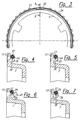
- Fig. 3 is a partial view of a according to the present Invention executed unit of synchronizer ring with ring spring for use, for example, in an arrangement similar to 2
- 4 to 7 show different design variants according to the invention in a section along the Line A-A in Fig. 3
- Fig. 8 shows another embodiment according to the present invention in one of FIG. 3 corresponding view
- FIG. 9 shows the enlarged detail IX in Fig. 8
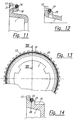
- Fig. 10 is a partial section along the Line X-X in Figures 8, 11 and 12 show different ones 10 corresponding representation
- Fig. 13 shows another embodiment according to the invention in partial view
- Fig. 14 the enlarged partial Section along the line XIV-XIV in Fig. 13,
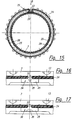
- Fig. 15 further embodiment according to the invention in part sectional view
- fig. 16 and 17 different Variants of the training each enlarged and in partial view along the arrow B in Fig. 15,
- Fig. 18 a partial Section through another embodiment of the invention
- Fig. 19 is an enlarged partial view along the arrow C in Fig. 18, Fig. 20 another embodiment according to the invention in, for example, FIG. 18 corresponding Partial section
- Fig. 21 is an enlarged partial view along the arrow D in FIGS. 20 and 22 the enlarged Detail E from Fig. 20.
- the synchronization device shown in Fig. 1 has one on a gear shaft 1 by means of a toothing 2 rotatably arranged synchronizer body 3, which is provided with a sliding sleeve-4 on its outer circumference, into which a shift lever, not shown, engages and with a detent consisting of bolt and spring 6 is provided. Furthermore, on the side of the synchronizer body 3 an outer synchronizer ring 7 arranged on its outer circumference corresponding to an internal toothing 8 of the sliding sleeve 4 is interlocked. A gear wheel 9 is free on the gear shaft 1 rotatably arranged, which has a toothing on its outer circumference 10 has.
- the clutch disc 11 is non-rotatably shaped or non-positive (e.g. gearing, laser welding, etc.) a corresponding approach of the gear 9 and stands with the Synchronizer body 3 via an engaging or disengaging if necessary Friction clutch in connection.
- This has a friction ring 14 on, which forms its own component and with its im Diameter larger side protruding cam 15 in matching recesses 16 of the clutch disc 11 engages.
- On every conical outer and inner surface is the Friction ring 14 here with a sintered one, for example Friction lining 17 provided with corresponding conical friction or coupling surfaces 18, 19 of the outer synchronizer ring 7 or an additional inner sync ring 20 cooperates.
- the outer synchronizer ring 7 is here as a deep-drawn Sheet metal part formed, which mentioned on its outer circumference External teeth 13 and the conical in the middle Friction surface or clutch surface 18 carries. Are on the inner circumference in the area of the deep-drawn floor for positive, non-rotatable connection punched with the synchronizer body 3
- Driving cams 21 provided in corresponding recesses 22 engage the synchronizer body 3.
- Coupling cams of the outer synchronizer ring 7 is here at the same time also the inner synchronizer ring 20 with the synchronizer body 3 coupled, which is an advantageous for many purposes, so-called double synchronization results.
- At the in the illustration left side of the synchronizer body 3 could be the same or similar arrangement for synchronizing another Gear wheel can be arranged on the transmission shaft 1.
- the cut according to Fig. 2 in the area of the outer synchronizer ring 7 by one of for example three circumferentially spaced by 120 ° arranged support elements 25 on the synchronizer ring 7 - between the spaced support elements 25 is the ring spring 24 exempted from the synchronizer ring 7 and can under the action of raised, elongated teeth 26 on the partially recessed inner toothing 8 of the Deform the sliding sleeve 4 radially inwards, after which the Sliding sleeve for positive coupling of the teeth 8, 13 and 12 can be moved to the far right in the illustration can.
- FIG. 5 several are similar to FIG. 4 Lugs distributed over the circumference as support elements 25 for Bent side of the sliding sleeve. In contrast to FIG. 4 a groove is now added to several or all tabs embossed, which centering and axial positioning of the Ring spring 24 guaranteed.
- each of the tab groups consists of three individual tabs 30, 31, on the outer circumference of the synchronizer ring 7 in the direction Sliding sleeve (here to the right) are bent.
- the two outer ones Tabs 30 are shaped so that they are the ring spring 24 both center and position axially.
- the middle curved tab 31 of each group only takes over the function the axial fixing of the ring spring 24.
- 13 and 14 are concerned a synchronizer ring 7 made of solid material with a closed Ring spring 24, both as a sheet metal ring as well can be made of solid material, the investment areas 28 of the support elements 25 when assembling the ring spring 24 due to lateral deformation of the support elements 25 are adaptable to the ring spring 24.
- the support elements 25 are here by stamping or by displacing of material from area 32 is generated axially to the left.
- synchronizer rings 7 with open ring spring 24 the open ends of the ring spring 24 when mounting on the synchronizer ring 7 for extensive adaptation to the investment areas 28 of the support elements 25 are adjustable relative to one another and can be fixed on the synchronizer ring 7.
- To fix the ends 33 of the open ring spring 24 are permanently deformable Holding areas 34 are provided on the synchronizer ring 7.
- a fixation of the Ends 33 of the ring spring 24 in a slot-like receptacle 36 of the holding area 34 can also be achieved in that a press body 37 after hanging the ring spring between the ends of which are pressed in.
- This press body 37 can for example be designed as a ball, pin, cone etc. be.
Landscapes
- Engineering & Computer Science (AREA)
- General Engineering & Computer Science (AREA)
- Mechanical Engineering (AREA)
- Mechanical Operated Clutches (AREA)
Description
Claims (10)
- Synchronring (7) mit geschlossener Ringfeder (24), für eine Synchronisierungseinrichtung für Schaltgetriebe, mit zumindest drei umfangsmäßig voneinander beabstandeten Auflageelementen (25) am Synchronring (7) für die im wesentlichen spielfrei auf diesen aufliegende Ringfeder (24), dadurch gekennzeichnet, daß die unmittelbaren Anlagebereiche (28) der Auflageelemente (25) für die Ringfeder (24) zum Ausgleich von Herstellungstoleranzen bei der Montage zumindest radial verstellbar sind.
- Synchronring nach Anspruch 1, dadurch gekennzeichnet, daß die Anlagebereiche (28) der Auflageelemente (25) am Synchronring (7) bei der Montage bleibend verformbar sind.
- Synchronring aus Vollmaterial nach Anspruch 2, dadurch gekennzeichnet, daß die Anlagebereiche (28) der Auflageelemente (25) am Synchronring (7) bei der Montage der Ringfeder (24) durch seitliche Deformation der Auflageelemente (25) an die Ringfeder (24) anpaßbar sind.
- Synchronring aus Vollmaterial nach Anspruch 2 oder 3, dadurch gekennzeichnet, daß die Anlagebereiche (28) der Auflageelemente (25) am Synchronring (7) bei der Montage der Ringfeder (24) durch von innen her wirkende Deformation der Auflageelemente (25) an die Ringfeder (24) anpaßbar sind.
- Synchronring als Blechumformteil nach Anspruch 2, dadurch gekennzeichnet, daß die Auflageelemente (25) bei der Umformung des Synchronringes (7) ausgebildet sind und in einem der Umformschritte an die aufgelegte Ringfeder (24) anpaßbar sind.
- Synchronring als Blechumformteil nach Anspruch 2, dadurch gekennzeichnet, daß die Auflageelemente (25) durch eine seitlich wirkende Deformation hergestellt und in einem der Umformschritte an die aufgelegte Ringfeder (24) anpaßbar sind.
- Synchronring (7) mit offener Ringfeder (24), für eine Synchronisierungseinrichtung für Schaltgetriebe, mit zumindest drei umfangsmäßig voneinander beabstandeten Auflageelementen (25) am Synchronring (7) für die im wesentlichen spielfrei auf diesen aufliegende Ringfeder (24), dadurch gekennzeichnet, daß die offenen Enden (33) der Ringfeder (24) zum Ausgleich von Herstellungstoleranzen bei der Montage durch umfangsmäßige Anpassung an die Anlagebereiche (28) der Auflageelemente (25) relativ zueinander verstellbar und am Synchronring (7) fixierbar sind.
- Synchronring nach Anspruch 7, dadurch gekennzeichnet, daß zur Fixierung der Enden (33) der offenen Ringfeder (24) bleibend verformbare Haltebereiche (34) am Synchronring (7) vorgesehen sind.
- Synchronring nach einem der Ansprüche 7 oder 8, dadurch gekennzeichnet, daß die Ringfeder (24) auf Auflageelementen (25) gemäß einem der Ansprüche 1 bis 6 gehalten ist.
- Synchronring nach einem oder mehreren der Ansprüche 1 bis 9, dadurch gekennzeichnet, daß die Ringfeder (24) mittels eines bleibend verformten Haltebereiches (34) auf dem Synchronring (7) unter Bildung einer Baugruppe unverlierbar gehalten ist.
Applications Claiming Priority (2)
| Application Number | Priority Date | Filing Date | Title |
|---|---|---|---|
| AT0178695A AT402225B (de) | 1995-10-30 | 1995-10-30 | Synchronring mit ringfeder |
| AT1786/95 | 1995-10-30 |
Publications (2)
| Publication Number | Publication Date |
|---|---|
| EP0771963A1 EP0771963A1 (de) | 1997-05-07 |
| EP0771963B1 true EP0771963B1 (de) | 1999-05-12 |
Family
ID=3520945
Family Applications (1)
| Application Number | Title | Priority Date | Filing Date |
|---|---|---|---|
| EP96890142A Expired - Lifetime EP0771963B1 (de) | 1995-10-30 | 1996-09-16 | Synchronring mit Ringfeder |
Country Status (6)
| Country | Link |
|---|---|
| US (1) | US5788036A (de) |
| EP (1) | EP0771963B1 (de) |
| JP (1) | JPH09177825A (de) |
| KR (1) | KR970021817A (de) |
| AT (1) | AT402225B (de) |
| DE (1) | DE59601865D1 (de) |
Families Citing this family (11)
| Publication number | Priority date | Publication date | Assignee | Title |
|---|---|---|---|---|
| DE19853856A1 (de) * | 1998-11-23 | 2000-05-25 | Schaeffler Waelzlager Ohg | Spanlos umgeformter Synchronring |
| DE19853896A1 (de) * | 1998-11-23 | 2000-05-25 | Schaeffler Waelzlager Ohg | Anordnung und Ausführung von Synchronringen als spanlos geformte Blechteile |
| FR2789139B1 (fr) * | 1999-02-02 | 2001-04-20 | Peugeot Citroen Automobiles Sa | Ensemble synchroniseur pour une transmission d'un vehicule automobile |
| JP3748749B2 (ja) | 1999-11-01 | 2006-02-22 | 本田技研工業株式会社 | トランスミッションの同期結合装置 |
| DE10203019A1 (de) * | 2002-01-26 | 2003-08-14 | Ina Schaeffler Kg | Mehrteiliger Synchronring einer Synchronisiereinrichtung |
| GB0216591D0 (en) * | 2002-07-17 | 2002-08-28 | Ford Global Tech Inc | Synchromesh device for a gear box |
| DE202009011782U1 (de) * | 2009-08-31 | 2011-01-13 | Hoerbiger Antriebstechnik Gmbh | Synchronring eines Schaltgetriebes |
| WO2013141216A1 (ja) * | 2012-03-23 | 2013-09-26 | オリンパスメディカルシステムズ株式会社 | 挿入装置 |
| DE102013225973B4 (de) * | 2013-12-16 | 2015-08-13 | Schaeffler Technologies AG & Co. KG | Synchroninnenring |
| SE539358C2 (en) * | 2015-11-19 | 2017-08-01 | Scania Cv Ab | A latch cone ring for a synchronizing arrangement, a synchronizing arrangement, a gearbox and a vehicle |
| CN112303142B (zh) * | 2020-10-29 | 2021-09-14 | 燕山大学 | 一种压力可控摩擦环式同步器 |
Family Cites Families (8)
| Publication number | Priority date | Publication date | Assignee | Title |
|---|---|---|---|---|
| DE933364C (de) * | 1942-09-16 | 1955-09-22 | Borg Warner | Synchronisiereinrichtung zur Schaltung von Zahnraederwechselgetrieben |
| US3247937A (en) * | 1964-05-04 | 1966-04-26 | Ford Motor Co | Synchronizer clutch assembly |
| GB1273898A (en) * | 1969-12-29 | 1972-05-10 | Honda Motor Co Ltd | Improvements in or relating to change gear mechanisms incorporating synchromesh |
| CA1262102A (en) * | 1984-06-14 | 1989-10-03 | Sadanori Nishimura | Inertia lock type synchronous clutch mechanism |
| US4776228A (en) * | 1986-07-07 | 1988-10-11 | Chrysler Motors Corporation | Strutless synchronizer |
| US4732247A (en) * | 1987-01-21 | 1988-03-22 | Chrysler Motors Corporation | Triple cone synchronizer with servo action |
| US4998445A (en) * | 1989-11-01 | 1991-03-12 | Tanaka Seimitu Kogyo Kabushiki Kaisha | Synchronizer ring |
| US5105927A (en) * | 1991-01-16 | 1992-04-21 | New Venture Gear, Inc. | Single cone servo action synchronizer |
-
1995
- 1995-10-30 AT AT0178695A patent/AT402225B/de not_active IP Right Cessation
-
1996
- 1996-09-16 DE DE59601865T patent/DE59601865D1/de not_active Expired - Lifetime
- 1996-09-16 EP EP96890142A patent/EP0771963B1/de not_active Expired - Lifetime
- 1996-10-23 US US08/734,956 patent/US5788036A/en not_active Expired - Fee Related
- 1996-10-28 KR KR1019960048963A patent/KR970021817A/ko not_active Withdrawn
- 1996-10-29 JP JP8287101A patent/JPH09177825A/ja active Pending
Also Published As
| Publication number | Publication date |
|---|---|
| EP0771963A1 (de) | 1997-05-07 |
| ATA178695A (de) | 1996-07-15 |
| US5788036A (en) | 1998-08-04 |
| KR970021817A (ko) | 1997-05-28 |
| AT402225B (de) | 1997-03-25 |
| JPH09177825A (ja) | 1997-07-11 |
| DE59601865D1 (de) | 1999-06-17 |
Similar Documents
| Publication | Publication Date | Title |
|---|---|---|
| DE3720885C2 (de) | Kupplung mit gedämpfter Schwungscheibe, insbesondere für Kraftfahrzeuge | |
| EP2274529B1 (de) | Blech-synchronring | |
| EP2913554B1 (de) | Federpaket, Kupplung und Kupplungsherstellungsverfahren | |
| EP2478243B1 (de) | Übertragungsring für eine synchronisierungsbaugruppe für ein schaltgetriebe | |
| EP2627919B1 (de) | Axiallageranordnung | |
| EP1518059A1 (de) | Synchroniserte getriebeschaltung mit hydraulischer betätigung | |
| AT402225B (de) | Synchronring mit ringfeder | |
| WO2019115124A1 (de) | Blech-lamellenträger sowie verfahren zu dessen drehzahlfestigkeitserhöhung | |
| EP1175569B1 (de) | Gebauter synchronkörper mit anschlagelement | |
| DE102005056827A1 (de) | Synchronring und Synchronkupplung | |
| DE102019126445A1 (de) | Verfahren zum Herstellen eines Bremssystems und Bremssystem | |
| DE102015100906B4 (de) | Synchronisiereinrichtung, Kupplungsanordnung und Antriebsanordnung | |
| DE102011114055A1 (de) | Synchronisiervorrichtung für ein Getriebe eines Kraftfahrzeuges | |
| EP3181932B1 (de) | Kupplungsanordnung mit verbesserter montage | |
| DE102006060535A1 (de) | Synchronisiereinrichtung für ein Schaltgetriebe | |
| DE102013215617C5 (de) | Kupplungskörper einer Synchronisiervorrichtung | |
| DE102011120343B4 (de) | Verfahren zur Herstellung eines Kupplungskörpers sowie Kupplungskörper für eine Synchronisiereinrichtung | |
| DE102016222892B4 (de) | Drehmomentübertragungseinrichtung | |
| EP2395255B1 (de) | Lösbare axiale Fixierung zweier Bauteile | |
| EP2478244B1 (de) | Schaltmuffe für ein schaltgetriebe | |
| EP2354602B1 (de) | Betätigungsvorrichtung für ein Zahnräderwechselgetriebe | |
| EP1146243B1 (de) | Synchronisiereinheit für Schaltkupplungen | |
| EP2103828B1 (de) | Kupplung | |
| DE102007032695A1 (de) | Synchronkörper einer Synchronisiereinrichtung für Schaltgetriebe | |
| DE102016203953A1 (de) | Synchronisierungsvorrichtung, insbesondere für ein Fahrzeuggetriebe |
Legal Events
| Date | Code | Title | Description |
|---|---|---|---|
| PUAI | Public reference made under article 153(3) epc to a published international application that has entered the european phase |
Free format text: ORIGINAL CODE: 0009012 |
|
| AK | Designated contracting states |
Kind code of ref document: A1 Designated state(s): DE FR GB IT |
|
| 17P | Request for examination filed |
Effective date: 19970819 |
|
| 17Q | First examination report despatched |
Effective date: 19971204 |
|
| GRAG | Despatch of communication of intention to grant |
Free format text: ORIGINAL CODE: EPIDOS AGRA |
|
| GRAG | Despatch of communication of intention to grant |
Free format text: ORIGINAL CODE: EPIDOS AGRA |
|
| GRAH | Despatch of communication of intention to grant a patent |
Free format text: ORIGINAL CODE: EPIDOS IGRA |
|
| GRAH | Despatch of communication of intention to grant a patent |
Free format text: ORIGINAL CODE: EPIDOS IGRA |
|
| GRAA | (expected) grant |
Free format text: ORIGINAL CODE: 0009210 |
|
| AK | Designated contracting states |
Kind code of ref document: B1 Designated state(s): DE FR GB IT |
|
| GBT | Gb: translation of ep patent filed (gb section 77(6)(a)/1977) |
Effective date: 19990517 |
|
| REF | Corresponds to: |
Ref document number: 59601865 Country of ref document: DE Date of ref document: 19990617 |
|
| ET | Fr: translation filed | ||
| PLBE | No opposition filed within time limit |
Free format text: ORIGINAL CODE: 0009261 |
|
| STAA | Information on the status of an ep patent application or granted ep patent |
Free format text: STATUS: NO OPPOSITION FILED WITHIN TIME LIMIT |
|
| 26N | No opposition filed | ||
| REG | Reference to a national code |
Ref country code: GB Ref legal event code: IF02 |
|
| PGFP | Annual fee paid to national office [announced via postgrant information from national office to epo] |
Ref country code: IT Payment date: 20080925 Year of fee payment: 13 Ref country code: FR Payment date: 20080826 Year of fee payment: 13 |
|
| PGFP | Annual fee paid to national office [announced via postgrant information from national office to epo] |
Ref country code: GB Payment date: 20080917 Year of fee payment: 13 |
|
| PGFP | Annual fee paid to national office [announced via postgrant information from national office to epo] |
Ref country code: DE Payment date: 20090828 Year of fee payment: 14 |
|
| GBPC | Gb: european patent ceased through non-payment of renewal fee |
Effective date: 20090916 |
|
| REG | Reference to a national code |
Ref country code: FR Ref legal event code: ST Effective date: 20100531 |
|
| PG25 | Lapsed in a contracting state [announced via postgrant information from national office to epo] |
Ref country code: FR Free format text: LAPSE BECAUSE OF NON-PAYMENT OF DUE FEES Effective date: 20090930 |
|
| PG25 | Lapsed in a contracting state [announced via postgrant information from national office to epo] |
Ref country code: GB Free format text: LAPSE BECAUSE OF NON-PAYMENT OF DUE FEES Effective date: 20090916 |
|
| PG25 | Lapsed in a contracting state [announced via postgrant information from national office to epo] |
Ref country code: IT Free format text: LAPSE BECAUSE OF NON-PAYMENT OF DUE FEES Effective date: 20090916 |
|
| REG | Reference to a national code |
Ref country code: DE Ref legal event code: R119 Ref document number: 59601865 Country of ref document: DE Effective date: 20110401 |
|
| PG25 | Lapsed in a contracting state [announced via postgrant information from national office to epo] |
Ref country code: DE Free format text: LAPSE BECAUSE OF NON-PAYMENT OF DUE FEES Effective date: 20110401 |