EP0771710A1 - Coach coupling assembly - Google Patents
Coach coupling assembly Download PDFInfo
- Publication number
- EP0771710A1 EP0771710A1 EP96850178A EP96850178A EP0771710A1 EP 0771710 A1 EP0771710 A1 EP 0771710A1 EP 96850178 A EP96850178 A EP 96850178A EP 96850178 A EP96850178 A EP 96850178A EP 0771710 A1 EP0771710 A1 EP 0771710A1
- Authority
- EP
- European Patent Office
- Prior art keywords
- coupling
- bore
- coach
- bearing
- arm
- Prior art date
- Legal status (The legal status is an assumption and is not a legal conclusion. Google has not performed a legal analysis and makes no representation as to the accuracy of the status listed.)
- Granted
Links
- 230000008878 coupling Effects 0.000 title claims abstract description 43
- 238000010168 coupling process Methods 0.000 title claims abstract description 43
- 238000005859 coupling reaction Methods 0.000 title claims abstract description 43
- 238000005096 rolling process Methods 0.000 claims abstract description 9
- 239000012858 resilient material Substances 0.000 claims abstract 4
- 230000000295 complement effect Effects 0.000 claims description 3
- 239000007788 liquid Substances 0.000 claims description 2
- 239000000314 lubricant Substances 0.000 claims description 2
- 239000010687 lubricating oil Substances 0.000 claims description 2
- 210000002445 nipple Anatomy 0.000 claims description 2
- 239000012530 fluid Substances 0.000 claims 1
- 238000013016 damping Methods 0.000 description 3
- 238000007789 sealing Methods 0.000 description 3
- 238000012423 maintenance Methods 0.000 description 1
- 238000004519 manufacturing process Methods 0.000 description 1
- 238000012986 modification Methods 0.000 description 1
- 230000004048 modification Effects 0.000 description 1
- 239000003921 oil Substances 0.000 description 1
Images
Classifications
-
- B—PERFORMING OPERATIONS; TRANSPORTING
- B62—LAND VEHICLES FOR TRAVELLING OTHERWISE THAN ON RAILS
- B62D—MOTOR VEHICLES; TRAILERS
- B62D47/00—Motor vehicles or trailers predominantly for carrying passengers
- B62D47/02—Motor vehicles or trailers predominantly for carrying passengers for large numbers of passengers, e.g. omnibus
- B62D47/025—Motor vehicles or trailers predominantly for carrying passengers for large numbers of passengers, e.g. omnibus articulated buses with interconnecting passageway, e.g. bellows
-
- B—PERFORMING OPERATIONS; TRANSPORTING
- B60—VEHICLES IN GENERAL
- B60D—VEHICLE CONNECTIONS
- B60D5/00—Gangways for coupled vehicles, e.g. of concertina type
-
- B—PERFORMING OPERATIONS; TRANSPORTING
- B61—RAILWAYS
- B61D—BODY DETAILS OR KINDS OF RAILWAY VEHICLES
- B61D3/00—Wagons or vans
- B61D3/10—Articulated vehicles
-
- B—PERFORMING OPERATIONS; TRANSPORTING
- B61—RAILWAYS
- B61G—COUPLINGS; DRAUGHT AND BUFFING APPLIANCES
- B61G5/00—Couplings for special purposes not otherwise provided for
- B61G5/02—Couplings for special purposes not otherwise provided for for coupling articulated trains, locomotives and tenders or the bogies of a vehicle; Coupling by means of a single coupling bar; Couplings preventing or limiting relative lateral movement of vehicles
Definitions
- the present invention refers to a coach coupling assembly for coupling together two coaches of a railbound multi-unit set of coaches in accordance with the preamble of the accompanying claim 1.
- Coaches of rolling stock are of two main types, one type being equipped with double wheel units, one at each end of the coach, whereas the other, trailing coach, has only one wheel unit located at that end of the coach, which shall not be connected to another coach.
- the coach has a fixed coupling device formed as a projecting beam with a vertically arranged socket intended to receive from above, a depending shaft journal arranged at the outer end of an arm projecting in longitudinal direction from the trailing coach end having no wheel unit.
- the depending shaft journal must be journalled in the socket to be able to make angular pivoting movements in the socket when the tram train or the like travels in curves etcetera.
- impacts and vibrations occuring during travel, e.g. at braking, could cause damage to the rolling bodies and race tracks of the rolling bearing used for journalling the shaft journal.
- this can preferably be done by providing the coupling with elastic damping means arranged to absorbe such impacts.
- EP-A1-0 612 646 refers to a coach coupling as described above, wherein the depending shaft journal is supported in a deep groove ball bearing.
- the impact damping means in this case is designed as an elastomeric linkage having a stiff inner body with a vertical centre bore for receiving the depending shaft journal, and a stiff outer body having a seat surface for the inner race ring of the ball bearing.
- the two stiff linkage bodies are spaced apart by a "hemi-spherical" elastomeric shell-formed body, and the two stiff linkage bodies have surfaces facing the shell-formed elastomeric body shaped to match the curvature of the "hemi-spherical" body. Manufacturing of such a linkage body is expensive and the design is partly open, whereby the coupling must be protected from dirt and moisture by means of an external sealing bellows.
- the purpose of the present invention is to provide a coach coupling in accordance with the preamble of the accompanying claim 1, which is designed in such a manner that it is compact in size and sealed off, and construed from inexpensive standard machine elements, and this has been achieved by giving the coupling the features defined in the characterizing part of the appended claim 1.
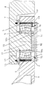
- the drawing shows a projecting first arm 1, which is fixedly connected to a not shown first coach. Near the free end of the first arm 1, there is provided a circular, vertical through hole 2, with a concentric bottom flange 3 of smaller diameter than the upper part of the hole 2.
- a sleeve-formed elastic lining 4 In the bore 2 is provided a sleeve-formed elastic lining 4.
- this lining 4 In the left hand half of the drawing this lining 4 is shown as a tubular bushing provided between the circumferential inner surface of the thorugh-bore 2 and the outer circumference of the bearing, but as can be seen in the right hand half this lining 4a, can have a inwardly directed bottom collar 4b, which in mounted position is situated between the flange 3 and the side face of the bearing.
- a double-row spherical roller bearing 5 is mounted with the circumference of its outer race ring fitting into this elastic lining 4, thus that the outer race ring of the bearing 5 in mounted position rests on the flange 3 of the first arm 1.
- the outer race ring of the bearing 5 is further secured from being removed from its mounted position in the elastic lining 4 in a direction upwards as shown in the drawing, by means of a ring 6 positioned concentric with the hole 2 in the first arm 1 and being removably fitted to this by means of screw joints 7 or the like, said ring having a center opening somewhat smaller than the outer diameter of the bearing 5, whereby the inner edge of ring 6 in mounted position prevents the bearing from leaving its mounted position within the lining 4.
- the double-row spherical bearing has a taper bore with its smaller diameter positioned at the bottom side of the bore 2 in the first arm 1.
- a second projecting arm 8 which is fixedly connected to another, preferably trailing, and not shown coach, has near its outer end a depending, tapering shaft journal 9 having a vertical axis.
- This tapering shaft journal 9 has a dimension being complementary to the dimension of the inner taper of the bearing 5, and when being mounted in the taper bore of the bearing 5 this tapering shaft journal 9 can be driven up to a zero clearance or a to a certain pre-tension.
- the bearing inner race ring After the bearing inner race ring has been driven up to desired internal clearance, it is affixed to the shaft journal 9 by means of a circular locking disc 10, which is fitted to the end of the shaft journal through the bottom opening of the hole 2, e.g. with bolts 11, and which disc 10 extends radially outside the shaft journal end.
- the tapering shaft journal 9 is further provided with a circumferential shoulder 12 at its bigger end, said shoulder 12 providing an abutment for the bearing inner race ring from moving in one direction, whereas said locking disc 10 prevents the inner race ring from moving in the opposite direction.
- the size of the internal clearance being adjustable by means of not shown shims or the like.
- the second arm 8 is further provided with an annular sealing device 13 positioned concentric to the center axis of the tapering shaft journal 9 and intended to form a sliding seal against the facing surface of the first arm 1, or, as shown in the drawing, against the bearing securing ring 6 attached to the first arm 1.
- the bottom opening of the bore 2 finally is covered by a cover disc 14, removably affixed thereto, e.g. by screw joints and having provided between itself and the goods of the first arm 1 an annular sealing device, such as an O-ring seal 15 provided in a groove in the cover disc or in the bottom surface of the first arm 1.
- a cover disc 14 removably affixed thereto, e.g. by screw joints and having provided between itself and the goods of the first arm 1 an annular sealing device, such as an O-ring seal 15 provided in a groove in the cover disc or in the bottom surface of the first arm 1.
- a sealed-off chamber 16 in which the bearing and the cooperating surfaces of the coach coupling are all enclosed.
- This sealingly closed chamber 16 protects the bearing and the coupling details from external dirt and moisture and it can preferably be completely filled with a liquid or semi-liquid lubricant via a lubricant nipple 17.
- the envelope surface of the shaft journal 9 and/or the bore of the inner race ring of the bearing 5 can be equipped with a helical groove 18a and 18b, respectively, (illustrated at the left hand side and the right hand side of the drawing), which via a duct 19 can be connected to a source of pressurized oil for facilitating dismantling of the coupling for repair and maintenance purposes.
- the shaft journal of the second arm and the bore of the inner race ring of the bearing have been shown having complementary tapering shapes, but it is also possible to use a cylindrical shaft journal which is mounted in a cylindric bore, even if the tapering embodiment will facilitate application of a desired internal clearance in the bearing and the introduction of the smaller shaft journal end into the bore in the inner bearing race ring.
Landscapes
- Engineering & Computer Science (AREA)
- Mechanical Engineering (AREA)
- Transportation (AREA)
- Chemical & Material Sciences (AREA)
- Combustion & Propulsion (AREA)
- Support Of The Bearing (AREA)
- Rolling Contact Bearings (AREA)
- Mounting Of Bearings Or Others (AREA)
Abstract
Description
- The present invention refers to a coach coupling assembly for coupling together two coaches of a railbound multi-unit set of coaches in accordance with the preamble of the accompanying
claim 1. - Coaches of rolling stock, such as tram trains, are of two main types, one type being equipped with double wheel units, one at each end of the coach, whereas the other, trailing coach, has only one wheel unit located at that end of the coach, which shall not be connected to another coach.
- At the end or ends, to be coupled together with a trailing coach, the coach has a fixed coupling device formed as a projecting beam with a vertically arranged socket intended to receive from above, a depending shaft journal arranged at the outer end of an arm projecting in longitudinal direction from the trailing coach end having no wheel unit.
- The depending shaft journal must be journalled in the socket to be able to make angular pivoting movements in the socket when the tram train or the like travels in curves etcetera. At a rigidly supported shaft journal, impacts and vibrations occuring during travel, e.g. at braking, could cause damage to the rolling bodies and race tracks of the rolling bearing used for journalling the shaft journal. For avoiding such damages it is essential to eliminate transfer of such impacts, vibrations etcetera, and this can preferably be done by providing the coupling with elastic damping means arranged to absorbe such impacts.
- Furthermore it is also essential to give the coupling a possibility of a certain relative movement about an imagined horizontal axis, for allowing travel over level differences without subjecting the bearing or the coupling means to stresses. Such adjustability can also, to a certain extent, be obtained with elastic damping means.
- EP-A1-0 612 646 refers to a coach coupling as described above, wherein the depending shaft journal is supported in a deep groove ball bearing. The impact damping means in this case is designed as an elastomeric linkage having a stiff inner body with a vertical centre bore for receiving the depending shaft journal, and a stiff outer body having a seat surface for the inner race ring of the ball bearing. The two stiff linkage bodies are spaced apart by a "hemi-spherical" elastomeric shell-formed body, and the two stiff linkage bodies have surfaces facing the shell-formed elastomeric body shaped to match the curvature of the "hemi-spherical" body. Manufacturing of such a linkage body is expensive and the design is partly open, whereby the coupling must be protected from dirt and moisture by means of an external sealing bellows.
- The purpose of the present invention is to provide a coach coupling in accordance with the preamble of the accompanying
claim 1, which is designed in such a manner that it is compact in size and sealed off, and construed from inexpensive standard machine elements, and this has been achieved by giving the coupling the features defined in the characterizing part of the appendedclaim 1. - Hereinafter the invention will be further described with reference to an embodiment of the coach coupling according to the present invention, shown in the accompanying drawing, and showing in a cross-section parts of the coupling arms and the articulated coupling itself.
- The drawing shows a projecting
first arm 1, which is fixedly connected to a not shown first coach. Near the free end of thefirst arm 1, there is provided a circular, vertical throughhole 2, with aconcentric bottom flange 3 of smaller diameter than the upper part of thehole 2. In thebore 2 is provided a sleeve-formedelastic lining 4. In the left hand half of the drawing thislining 4 is shown as a tubular bushing provided between the circumferential inner surface of the thorugh-bore 2 and the outer circumference of the bearing, but as can be seen in the right hand half this lining 4a, can have a inwardly directed bottom collar 4b, which in mounted position is situated between theflange 3 and the side face of the bearing. - A double-row spherical roller bearing 5 is mounted with the circumference of its outer race ring fitting into this
elastic lining 4, thus that the outer race ring of the bearing 5 in mounted position rests on theflange 3 of thefirst arm 1. The outer race ring of thebearing 5 is further secured from being removed from its mounted position in theelastic lining 4 in a direction upwards as shown in the drawing, by means of aring 6 positioned concentric with thehole 2 in thefirst arm 1 and being removably fitted to this by means ofscrew joints 7 or the like, said ring having a center opening somewhat smaller than the outer diameter of thebearing 5, whereby the inner edge ofring 6 in mounted position prevents the bearing from leaving its mounted position within thelining 4. The double-row spherical bearing has a taper bore with its smaller diameter positioned at the bottom side of thebore 2 in thefirst arm 1. - A second projecting
arm 8, which is fixedly connected to another, preferably trailing, and not shown coach, has near its outer end a depending, taperingshaft journal 9 having a vertical axis. This taperingshaft journal 9 has a dimension being complementary to the dimension of the inner taper of thebearing 5, and when being mounted in the taper bore of thebearing 5 this taperingshaft journal 9 can be driven up to a zero clearance or a to a certain pre-tension. After the bearing inner race ring has been driven up to desired internal clearance, it is affixed to theshaft journal 9 by means of acircular locking disc 10, which is fitted to the end of the shaft journal through the bottom opening of thehole 2, e.g. withbolts 11, and whichdisc 10 extends radially outside the shaft journal end. - The tapering
shaft journal 9 is further provided with acircumferential shoulder 12 at its bigger end, saidshoulder 12 providing an abutment for the bearing inner race ring from moving in one direction, whereas saidlocking disc 10 prevents the inner race ring from moving in the opposite direction. The size of the internal clearance being adjustable by means of not shown shims or the like.
Thesecond arm 8 is further provided with anannular sealing device 13 positioned concentric to the center axis of the taperingshaft journal 9 and intended to form a sliding seal against the facing surface of thefirst arm 1, or, as shown in the drawing, against thebearing securing ring 6 attached to thefirst arm 1. - The bottom opening of the
bore 2 finally is covered by acover disc 14, removably affixed thereto, e.g. by screw joints and having provided between itself and the goods of thefirst arm 1 an annular sealing device, such as an O-ring seal 15 provided in a groove in the cover disc or in the bottom surface of thefirst arm 1. - By provision of the
seal 13 and thecover disc 14 with itsseal 15, it is provided a sealed-offchamber 16 in which the bearing and the cooperating surfaces of the coach coupling are all enclosed. This sealingly closedchamber 16 protects the bearing and the coupling details from external dirt and moisture and it can preferably be completely filled with a liquid or semi-liquid lubricant via alubricant nipple 17. - The envelope surface of the
shaft journal 9 and/or the bore of the inner race ring of thebearing 5 can be equipped with ahelical groove duct 19 can be connected to a source of pressurized oil for facilitating dismantling of the coupling for repair and maintenance purposes. - In this manner it has been provided a reliable, simple and cost efficient coach coupling of the type mentioned initially which is construed mainly from standard machine components and where the sleeve-formed
elastical lining 4 takes up and absorbs radial forces, whereas the spherical roller bearing 5 provides a smooth operation at angular movements when the centre axes of thebore 2 in thefirst arm 1 and theshaft journal 9 on thesecond arm 8 coincide, but also, due to the self-aligning properties of the spherical roller bearing, when misalignments occur between these two axes. - The invention is not limited to the embodiments shown in the drawings and described in connection thereto but modifications and variations are possible within the scope of the appended claims. Thus, although the bearing has been shown and described as a double-row spherical roller bearing, it could, without departing from the scope of the invention, be substitued by any other rolling bearing having self-aligning properties similar or nearly similar to a spherical roller bearing. The shaft journal of the second arm and the bore of the inner race ring of the bearing have been shown having complementary tapering shapes, but it is also possible to use a cylindrical shaft journal which is mounted in a cylindric bore, even if the tapering embodiment will facilitate application of a desired internal clearance in the bearing and the introduction of the smaller shaft journal end into the bore in the inner bearing race ring.
Claims (10)
- A coach coupling assembly for coupling together two coaches of a railbound multi-unit set of coaches, having a first coupling arm (1) fixedly connected to a first one of said coaches, and a second coupling arm (8) fixedly connected to a second one of said coaches, the first arm (1) having a substantially vertically arranged through-bore (2), housing the outer race ring of a rolling bearing (5), in the bore of the inner race ring of which, is received a depending shaft journal (9) fixedly fitted to said second coupling arm (8), and means provided to take up and damp radial forces acting upon the coupling and to compensate for misalignment between the axes of the said through-bore (2) and said shaft journal (9),
characterized therein,
that the through-bore (2) of the first arm (1) is provided with an elastic lining (4,4a) of a resilient material, and that the bearing used is an angularly self-aligning rolling bearing (5) permitting a certain degree of misalignment between the axes of the through-bore (2) and the shaft journal (9), and being fitted inside said lining (4,4a), which is thereby adapted to take up and dampen radial forces acting upon the coupling. - A coach coupling as claimed in claim 1,
characterized therein,
that the lining is a tubular sleeve (4) of elastically resilient material. - A coach coupling as claimed in claim 1,
characterized therein,
that the lining is a sleeve (4a) of elastically resilient material, provided with a radially inwardly extending collar (4b) at the end to be inserted into the through-bore (2). - A coach coupling as claimed in anyone of the preceding claims,
characterized therein,
that the rolling bearing is a double-row spherical roller bearing (5). - A coach coupling according to anyone of the preceding claims,
characterized therein,
that the bearing (5) and the coupling components (2, 4, 9) are enclosed in a sealed-off chamber (16). - A coach coupling as claimed in claim 5,
characterized therein,
that the sealed-off chamber (16) is provided with a lubricant nipple (17) for introduction of a liquid or semi-liquid lubricant therein. - A coach coupling as claimed in anyone of the preceding claims,
characterized therein,
that the shaft journal (9) of the second arm (2) and the bore of the inner race ring of the bearing (5) have complementary tapering shapes. - A coach coupling as claimed in anyone of the preceding claims,
characterized therein,
that the race rings of the bearing (5) are secured to the first and second arms (1, 2) resp. by means of fixed abutment surfaces (3 and 5 resp.) and removably fixed locking elements (6 and 10 resp.). - A coach coupling as claimed in anyone of the preceding claims,
characterized therein,
that the bottom side of the through-bore (2) in the first coupling arm (1) is sealingly covered by a separate removable cover member (14). - A coach coupling as claimed in anyone of the preceding claims,
characterized therein,
that the envelope surface of the shaft journal (9) and/or the bore of the inner race ring of the bearing (5) is/are equipped with a helical groove (18a, 18b), which via a duct (19) is connectable to a source of pressurized fluid for dismantling purposes.
Applications Claiming Priority (2)
| Application Number | Priority Date | Filing Date | Title |
|---|---|---|---|
| SE9503808 | 1995-10-30 | ||
| SE9503808A SE9503808L (en) | 1995-10-30 | 1995-10-30 | Car coupler unit |
Publications (2)
| Publication Number | Publication Date |
|---|---|
| EP0771710A1 true EP0771710A1 (en) | 1997-05-07 |
| EP0771710B1 EP0771710B1 (en) | 1999-07-28 |
Family
ID=20400004
Family Applications (1)
| Application Number | Title | Priority Date | Filing Date |
|---|---|---|---|
| EP96850178A Expired - Lifetime EP0771710B1 (en) | 1995-10-30 | 1996-10-24 | Coach coupling assembly |
Country Status (6)
| Country | Link |
|---|---|
| US (1) | US5906164A (en) |
| EP (1) | EP0771710B1 (en) |
| JP (1) | JP2891677B2 (en) |
| CN (1) | CN1157239A (en) |
| DE (1) | DE69603437T2 (en) |
| SE (1) | SE9503808L (en) |
Cited By (4)
| Publication number | Priority date | Publication date | Assignee | Title |
|---|---|---|---|---|
| EP1067034A1 (en) * | 1999-07-06 | 2001-01-10 | Jean-Michel Ven | Rolling railway equipment, especially for the transport of road vehicles |
| DE10153460A1 (en) * | 2001-10-30 | 2003-05-22 | Voith Turbo Scharfenberg Gmbh | Railcar or wagon coupling offers lengthways maneuvrability via destructive buffer to guard against overloading of cars and coupling forks and bolt lashing. |
| WO2005023619A1 (en) | 2003-09-10 | 2005-03-17 | Dellner Couplers Ab | Rail-mounted car having an articulated joint for permanently connecting two underbodies of the rail-mounted car |
| EP2851219A1 (en) * | 2013-09-18 | 2015-03-25 | Alfred Kärcher GmbH & Co. KG | Articulated joint for an implement carrier vehicle and an implement carrier vehicle comprising such articulated joint |
Families Citing this family (12)
| Publication number | Priority date | Publication date | Assignee | Title |
|---|---|---|---|---|
| JP3422926B2 (en) * | 1998-04-24 | 2003-07-07 | 近畿車輌株式会社 | Underframe structure of articulation |
| EP1038761B1 (en) * | 1999-03-19 | 2001-07-04 | HÜBNER GmbH | Articulated connection positioned on the roof for the articulated connection of two vehicles |
| US8157450B2 (en) * | 2008-08-22 | 2012-04-17 | Baldor Electric Company | Waveform expansion sleeve for a bearing |
| EP2409860B1 (en) * | 2010-07-21 | 2012-12-05 | Hübner GmbH | Swing bearing joint |
| DE102010046495B3 (en) * | 2010-09-24 | 2011-11-10 | Hübner GmbH | Joint of an articulated vehicle |
| GB2489021B (en) * | 2011-03-16 | 2013-08-14 | Flybrid Automotive Ltd | High speed flywheel |
| DE102014206870B4 (en) * | 2014-04-09 | 2022-09-08 | Aktiebolaget Skf | Bearing arrangement and method for its manufacture |
| US9701323B2 (en) | 2015-04-06 | 2017-07-11 | Bedloe Industries Llc | Railcar coupler |
| CN105539490B (en) * | 2015-12-28 | 2018-06-12 | 勾长虹 | For the attachment device between rail vehicle |
| CN108819629A (en) * | 2018-07-05 | 2018-11-16 | 王秀丽 | It is a kind of that car bracket is dragged based on industrial machinery |
| GB2578903B (en) * | 2018-11-13 | 2021-08-25 | Arrival Ltd | Two wheel automatic guided vehicles |
| CN111572654B (en) * | 2020-03-30 | 2021-09-28 | 青岛海山慧谷科技有限公司 | Multi-compartment rapid transfer self-organizing public transportation system and method |
Citations (3)
| Publication number | Priority date | Publication date | Assignee | Title |
|---|---|---|---|---|
| US3687084A (en) * | 1969-07-17 | 1972-08-29 | Acf Ind Inc | Articulated car train |
| FR2695612A1 (en) * | 1992-09-11 | 1994-03-18 | Alsthom Gec | Ball and socket connecting device used for rail vehicles - includes first piece fixed on one of vehicles and having ball for ball and socket joint and second piece fixed to other vehicle and having socket for this joint, with socket and ball having contact surface greater than hemi-sphere |
| WO1994020766A1 (en) * | 1993-03-11 | 1994-09-15 | Wagner Mining And Construction Equipment Co. | Articulated vehicle and hinge assembly |
Family Cites Families (11)
| Publication number | Priority date | Publication date | Assignee | Title |
|---|---|---|---|---|
| US2070081A (en) * | 1935-07-29 | 1937-02-09 | Henry Raymond | Bearing support |
| US2141122A (en) * | 1937-12-22 | 1938-12-20 | Timken Roller Bearing Co | Cushioned roller bearing |
| GB666805A (en) * | 1949-08-24 | 1952-02-20 | English Electric Co Ltd | Improvements in and relating to locomotive side rods |
| US2565759A (en) * | 1949-09-29 | 1951-08-28 | Danly Mach Specialties Inc | Flywheel bearing demounting assembly |
| JPS6356313U (en) * | 1986-09-30 | 1988-04-15 | ||
| US5044785A (en) * | 1990-06-18 | 1991-09-03 | Eaton Corporation | Bearing isolator |
| JPH0429130U (en) * | 1990-06-29 | 1992-03-09 | ||
| DE9103935U1 (en) * | 1991-03-30 | 1991-06-27 | J.M. Voith Gmbh, 7920 Heidenheim | Bearing housing for a multi-row rolling bearing or for several coaxially arranged rolling bearings |
| DE4305614A1 (en) * | 1993-02-24 | 1994-08-25 | Linke Hofmann Busch | Articulated connection for the articulated connection of vehicle parts of a multi-unit rail vehicle |
| FR2716149B1 (en) * | 1994-02-15 | 1996-03-29 | Gec Alsthom Transport Sa | Coupling joint and energy absorption method between two railway vehicles. |
| DE9420230U1 (en) * | 1994-12-21 | 1995-03-23 | AEG Schienenfahrzeuge GmbH, 90461 Nürnberg | Articulated bearings for rail vehicles |
-
1995
- 1995-10-30 SE SE9503808A patent/SE9503808L/en not_active IP Right Cessation
-
1996
- 1996-10-24 DE DE69603437T patent/DE69603437T2/en not_active Expired - Fee Related
- 1996-10-24 EP EP96850178A patent/EP0771710B1/en not_active Expired - Lifetime
- 1996-10-28 US US08/740,323 patent/US5906164A/en not_active Expired - Fee Related
- 1996-10-29 JP JP8302367A patent/JP2891677B2/en not_active Expired - Lifetime
- 1996-10-29 CN CN96122693.5A patent/CN1157239A/en active Pending
Patent Citations (3)
| Publication number | Priority date | Publication date | Assignee | Title |
|---|---|---|---|---|
| US3687084A (en) * | 1969-07-17 | 1972-08-29 | Acf Ind Inc | Articulated car train |
| FR2695612A1 (en) * | 1992-09-11 | 1994-03-18 | Alsthom Gec | Ball and socket connecting device used for rail vehicles - includes first piece fixed on one of vehicles and having ball for ball and socket joint and second piece fixed to other vehicle and having socket for this joint, with socket and ball having contact surface greater than hemi-sphere |
| WO1994020766A1 (en) * | 1993-03-11 | 1994-09-15 | Wagner Mining And Construction Equipment Co. | Articulated vehicle and hinge assembly |
Cited By (6)
| Publication number | Priority date | Publication date | Assignee | Title |
|---|---|---|---|---|
| EP1067034A1 (en) * | 1999-07-06 | 2001-01-10 | Jean-Michel Ven | Rolling railway equipment, especially for the transport of road vehicles |
| FR2796026A1 (en) * | 1999-07-06 | 2001-01-12 | Jean Michel Ven | ROLLING RAIL EQUIPMENT, PARTICULARLY FOR THE TRANSPORT OF HEAVY VEHICLES |
| DE10153460A1 (en) * | 2001-10-30 | 2003-05-22 | Voith Turbo Scharfenberg Gmbh | Railcar or wagon coupling offers lengthways maneuvrability via destructive buffer to guard against overloading of cars and coupling forks and bolt lashing. |
| WO2005023619A1 (en) | 2003-09-10 | 2005-03-17 | Dellner Couplers Ab | Rail-mounted car having an articulated joint for permanently connecting two underbodies of the rail-mounted car |
| EP2851219A1 (en) * | 2013-09-18 | 2015-03-25 | Alfred Kärcher GmbH & Co. KG | Articulated joint for an implement carrier vehicle and an implement carrier vehicle comprising such articulated joint |
| WO2015039958A1 (en) * | 2013-09-18 | 2015-03-26 | Alfred Kärcher Gmbh & Co. Kg | Articulated joint for an implement carrier vehicle and an implement carrier vehicle comprising such articulated joint |
Also Published As
| Publication number | Publication date |
|---|---|
| US5906164A (en) | 1999-05-25 |
| SE504051C2 (en) | 1996-10-28 |
| JP2891677B2 (en) | 1999-05-17 |
| DE69603437T2 (en) | 2000-01-13 |
| SE9503808L (en) | 1996-10-28 |
| DE69603437D1 (en) | 1999-09-02 |
| CN1157239A (en) | 1997-08-20 |
| SE9503808D0 (en) | 1995-10-30 |
| JPH09164950A (en) | 1997-06-24 |
| EP0771710B1 (en) | 1999-07-28 |
Similar Documents
| Publication | Publication Date | Title |
|---|---|---|
| EP0771710B1 (en) | Coach coupling assembly | |
| AU2012299319C1 (en) | Stabilized backing ring and stabilizing ring therefor | |
| CN102036835B (en) | Device comprising wheel hub and constant-velocity rotary joint | |
| ES2397269T3 (en) | Device for the regulation of the inclination and / or of the wheel suspension of wheel suspensions | |
| US5456185A (en) | Hinge connection for connecting vehicle parts of a multiple-unit rail-borne vehicle in an articulated manner | |
| KR970006006B1 (en) | Centered double joint for articluated shafts in vehicles | |
| GB2296226A (en) | An articulated coupling for railway vehicles | |
| CN102427961A (en) | Joint and/or bearing assembly having an elastic intermediate layer | |
| US4997407A (en) | Centered double joint with lubrication | |
| US6267683B1 (en) | Assembly having a constant velocity joint and a receiving part | |
| CN101208210A (en) | Ball-shaped coupling comprising a sealed contact area | |
| JPH02502561A (en) | pivot assembly | |
| EA015613B1 (en) | Bogie with two-part frame | |
| RU2180713C2 (en) | Gear joint | |
| US20110240585A1 (en) | Coupling unit | |
| US20060199650A1 (en) | Centering device for mutually centering two shaft ends | |
| CZ68693A3 (en) | Bogie for railway, particularly low-clearance vehicles | |
| SU1138013A3 (en) | Hydraulic piston car retarder for braking railway rolling stock | |
| US1981173A (en) | Driving mechanism for steering wheels of motor vehicles | |
| ES2264999T3 (en) | GASKET SYSTEM FOR AN ARTICULATED CRUISE BULON. | |
| CN111656030A (en) | Joint bearing for a motor vehicle wheel module | |
| US6174240B1 (en) | Constant velocity universal joint with lubricant reservoir | |
| RU94533U1 (en) | HINGED AUTO CHAIN ASSEMBLY | |
| US3453012A (en) | Universal joint having wear resistant supporting ring for pivotally supporting the hinge pin in the joint housing | |
| RU87742U1 (en) | BOTH MOTOR SHAFT |
Legal Events
| Date | Code | Title | Description |
|---|---|---|---|
| PUAI | Public reference made under article 153(3) epc to a published international application that has entered the european phase |
Free format text: ORIGINAL CODE: 0009012 |
|
| AK | Designated contracting states |
Kind code of ref document: A1 Designated state(s): DE FR GB IT |
|
| 17P | Request for examination filed |
Effective date: 19971107 |
|
| GRAG | Despatch of communication of intention to grant |
Free format text: ORIGINAL CODE: EPIDOS AGRA |
|
| GRAG | Despatch of communication of intention to grant |
Free format text: ORIGINAL CODE: EPIDOS AGRA |
|
| GRAH | Despatch of communication of intention to grant a patent |
Free format text: ORIGINAL CODE: EPIDOS IGRA |
|
| 17Q | First examination report despatched |
Effective date: 19990119 |
|
| GRAH | Despatch of communication of intention to grant a patent |
Free format text: ORIGINAL CODE: EPIDOS IGRA |
|
| GRAA | (expected) grant |
Free format text: ORIGINAL CODE: 0009210 |
|
| AK | Designated contracting states |
Kind code of ref document: B1 Designated state(s): DE FR GB IT |
|
| ET | Fr: translation filed | ||
| REF | Corresponds to: |
Ref document number: 69603437 Country of ref document: DE Date of ref document: 19990902 |
|
| PGFP | Annual fee paid to national office [announced via postgrant information from national office to epo] |
Ref country code: FR Payment date: 19990930 Year of fee payment: 4 |
|
| PGFP | Annual fee paid to national office [announced via postgrant information from national office to epo] |
Ref country code: DE Payment date: 19991001 Year of fee payment: 4 |
|
| ITF | It: translation for a ep patent filed | ||
| PLBE | No opposition filed within time limit |
Free format text: ORIGINAL CODE: 0009261 |
|
| STAA | Information on the status of an ep patent application or granted ep patent |
Free format text: STATUS: NO OPPOSITION FILED WITHIN TIME LIMIT |
|
| 26N | No opposition filed | ||
| PG25 | Lapsed in a contracting state [announced via postgrant information from national office to epo] |
Ref country code: GB Free format text: LAPSE BECAUSE OF NON-PAYMENT OF DUE FEES Effective date: 20001024 |
|
| GBPC | Gb: european patent ceased through non-payment of renewal fee |
Effective date: 20001024 |
|
| PG25 | Lapsed in a contracting state [announced via postgrant information from national office to epo] |
Ref country code: FR Free format text: LAPSE BECAUSE OF NON-PAYMENT OF DUE FEES Effective date: 20010629 |
|
| PG25 | Lapsed in a contracting state [announced via postgrant information from national office to epo] |
Ref country code: DE Free format text: LAPSE BECAUSE OF NON-PAYMENT OF DUE FEES Effective date: 20010703 |
|
| REG | Reference to a national code |
Ref country code: FR Ref legal event code: ST |
|
| PG25 | Lapsed in a contracting state [announced via postgrant information from national office to epo] |
Ref country code: IT Free format text: LAPSE BECAUSE OF NON-PAYMENT OF DUE FEES Effective date: 20051024 |