EP0771485B1 - Device for closing sheathings such as cable conduits - Google Patents
Device for closing sheathings such as cable conduits Download PDFInfo
- Publication number
- EP0771485B1 EP0771485B1 EP95924283A EP95924283A EP0771485B1 EP 0771485 B1 EP0771485 B1 EP 0771485B1 EP 95924283 A EP95924283 A EP 95924283A EP 95924283 A EP95924283 A EP 95924283A EP 0771485 B1 EP0771485 B1 EP 0771485B1
- Authority
- EP
- European Patent Office
- Prior art keywords
- accordance
- tool
- elements
- cable
- closure
- Prior art date
- Legal status (The legal status is an assumption and is not a legal conclusion. Google has not performed a legal analysis and makes no representation as to the accuracy of the status listed.)
- Expired - Lifetime
Links
- 239000000853 adhesive Substances 0.000 claims description 21
- 230000001070 adhesive effect Effects 0.000 claims description 21
- 238000000034 method Methods 0.000 claims description 19
- 230000008569 process Effects 0.000 claims description 13
- 238000004519 manufacturing process Methods 0.000 claims description 5
- 239000011159 matrix material Substances 0.000 claims description 4
- 238000002360 preparation method Methods 0.000 claims description 4
- 230000003287 optical effect Effects 0.000 claims description 3
- 230000001105 regulatory effect Effects 0.000 claims 7
- 238000006073 displacement reaction Methods 0.000 claims 2
- 238000003466 welding Methods 0.000 description 7
- 238000012549 training Methods 0.000 description 4
- 238000013461 design Methods 0.000 description 3
- 238000010586 diagram Methods 0.000 description 2
- 238000002347 injection Methods 0.000 description 2
- 239000007924 injection Substances 0.000 description 2
- 238000007789 sealing Methods 0.000 description 2
- 230000007480 spreading Effects 0.000 description 2
- 238000003892 spreading Methods 0.000 description 2
- XLYOFNOQVPJJNP-UHFFFAOYSA-N water Substances O XLYOFNOQVPJJNP-UHFFFAOYSA-N 0.000 description 2
- 230000000712 assembly Effects 0.000 description 1
- 238000000429 assembly Methods 0.000 description 1
- 230000008859 change Effects 0.000 description 1
- 238000001514 detection method Methods 0.000 description 1
- 230000000694 effects Effects 0.000 description 1
- 125000000524 functional group Chemical group 0.000 description 1
- 239000003292 glue Substances 0.000 description 1
- 238000010438 heat treatment Methods 0.000 description 1
- 230000001771 impaired effect Effects 0.000 description 1
- 230000006872 improvement Effects 0.000 description 1
- 238000011835 investigation Methods 0.000 description 1
- 239000000463 material Substances 0.000 description 1
- 230000013011 mating Effects 0.000 description 1
- 238000005259 measurement Methods 0.000 description 1
- 230000007246 mechanism Effects 0.000 description 1
- 210000000056 organ Anatomy 0.000 description 1
- 238000009420 retrofitting Methods 0.000 description 1
- 238000000926 separation method Methods 0.000 description 1
- 239000007787 solid Substances 0.000 description 1
- 239000000243 solution Substances 0.000 description 1
- 239000007921 spray Substances 0.000 description 1
- 238000012546 transfer Methods 0.000 description 1
- 230000001960 triggered effect Effects 0.000 description 1
Images


Classifications
-
- A—HUMAN NECESSITIES
- A44—HABERDASHERY; JEWELLERY
- A44B—BUTTONS, PINS, BUCKLES, SLIDE FASTENERS, OR THE LIKE
- A44B19/00—Slide fasteners
- A44B19/24—Details
- A44B19/26—Sliders
- A44B19/28—Sliders constructed to be removable from at least one stringer ; Sliders with movable parts to permit releasing of the slider in the event of jamming or obstruction
- A44B19/285—Tools for opening or closing slide fasteners
-
- B—PERFORMING OPERATIONS; TRANSPORTING
- B25—HAND TOOLS; PORTABLE POWER-DRIVEN TOOLS; MANIPULATORS
- B25B—TOOLS OR BENCH DEVICES NOT OTHERWISE PROVIDED FOR, FOR FASTENING, CONNECTING, DISENGAGING OR HOLDING
- B25B25/00—Implements for fastening, connecting or tensioning of wire or strip
- B25B25/005—Implements for fastening, connecting or tensioning of wire or strip for applying wire clasps to hose couplings
-
- B—PERFORMING OPERATIONS; TRANSPORTING
- B25—HAND TOOLS; PORTABLE POWER-DRIVEN TOOLS; MANIPULATORS
- B25B—TOOLS OR BENCH DEVICES NOT OTHERWISE PROVIDED FOR, FOR FASTENING, CONNECTING, DISENGAGING OR HOLDING
- B25B27/00—Hand tools, specially adapted for fitting together or separating parts or objects whether or not involving some deformation, not otherwise provided for
- B25B27/14—Hand tools, specially adapted for fitting together or separating parts or objects whether or not involving some deformation, not otherwise provided for for assembling objects other than by press fit or detaching same
- B25B27/146—Clip clamping hand tools
-
- H—ELECTRICITY
- H02—GENERATION; CONVERSION OR DISTRIBUTION OF ELECTRIC POWER
- H02G—INSTALLATION OF ELECTRIC CABLES OR LINES, OR OF COMBINED OPTICAL AND ELECTRIC CABLES OR LINES
- H02G1/00—Methods or apparatus specially adapted for installing, maintaining, repairing or dismantling electric cables or lines
-
- Y—GENERAL TAGGING OF NEW TECHNOLOGICAL DEVELOPMENTS; GENERAL TAGGING OF CROSS-SECTIONAL TECHNOLOGIES SPANNING OVER SEVERAL SECTIONS OF THE IPC; TECHNICAL SUBJECTS COVERED BY FORMER USPC CROSS-REFERENCE ART COLLECTIONS [XRACs] AND DIGESTS
- Y10—TECHNICAL SUBJECTS COVERED BY FORMER USPC
- Y10T—TECHNICAL SUBJECTS COVERED BY FORMER US CLASSIFICATION
- Y10T29/00—Metal working
- Y10T29/49—Method of mechanical manufacture
- Y10T29/49764—Method of mechanical manufacture with testing or indicating
- Y10T29/49771—Quantitative measuring or gauging
-
- Y—GENERAL TAGGING OF NEW TECHNOLOGICAL DEVELOPMENTS; GENERAL TAGGING OF CROSS-SECTIONAL TECHNOLOGIES SPANNING OVER SEVERAL SECTIONS OF THE IPC; TECHNICAL SUBJECTS COVERED BY FORMER USPC CROSS-REFERENCE ART COLLECTIONS [XRACs] AND DIGESTS
- Y10—TECHNICAL SUBJECTS COVERED BY FORMER USPC
- Y10T—TECHNICAL SUBJECTS COVERED BY FORMER US CLASSIFICATION
- Y10T29/00—Metal working
- Y10T29/49—Method of mechanical manufacture
- Y10T29/49826—Assembling or joining
- Y10T29/49833—Punching, piercing or reaming part by surface of second part
- Y10T29/49835—Punching, piercing or reaming part by surface of second part with shaping
-
- Y—GENERAL TAGGING OF NEW TECHNOLOGICAL DEVELOPMENTS; GENERAL TAGGING OF CROSS-SECTIONAL TECHNOLOGIES SPANNING OVER SEVERAL SECTIONS OF THE IPC; TECHNICAL SUBJECTS COVERED BY FORMER USPC CROSS-REFERENCE ART COLLECTIONS [XRACs] AND DIGESTS
- Y10—TECHNICAL SUBJECTS COVERED BY FORMER USPC
- Y10T—TECHNICAL SUBJECTS COVERED BY FORMER US CLASSIFICATION
- Y10T29/00—Metal working
- Y10T29/49—Method of mechanical manufacture
- Y10T29/49826—Assembling or joining
- Y10T29/49947—Assembling or joining by applying separate fastener
- Y10T29/49954—Fastener deformed after application
- Y10T29/49956—Riveting
- Y10T29/49957—At least one part nonmetallic
-
- Y—GENERAL TAGGING OF NEW TECHNOLOGICAL DEVELOPMENTS; GENERAL TAGGING OF CROSS-SECTIONAL TECHNOLOGIES SPANNING OVER SEVERAL SECTIONS OF THE IPC; TECHNICAL SUBJECTS COVERED BY FORMER USPC CROSS-REFERENCE ART COLLECTIONS [XRACs] AND DIGESTS
- Y10—TECHNICAL SUBJECTS COVERED BY FORMER USPC
- Y10T—TECHNICAL SUBJECTS COVERED BY FORMER US CLASSIFICATION
- Y10T29/00—Metal working
- Y10T29/49—Method of mechanical manufacture
- Y10T29/49826—Assembling or joining
- Y10T29/49947—Assembling or joining by applying separate fastener
- Y10T29/49959—Nonresilient fastener
-
- Y—GENERAL TAGGING OF NEW TECHNOLOGICAL DEVELOPMENTS; GENERAL TAGGING OF CROSS-SECTIONAL TECHNOLOGIES SPANNING OVER SEVERAL SECTIONS OF THE IPC; TECHNICAL SUBJECTS COVERED BY FORMER USPC CROSS-REFERENCE ART COLLECTIONS [XRACs] AND DIGESTS
- Y10—TECHNICAL SUBJECTS COVERED BY FORMER USPC
- Y10T—TECHNICAL SUBJECTS COVERED BY FORMER US CLASSIFICATION
- Y10T29/00—Metal working
- Y10T29/49—Method of mechanical manufacture
- Y10T29/49826—Assembling or joining
- Y10T29/49947—Assembling or joining by applying separate fastener
- Y10T29/49966—Assembling or joining by applying separate fastener with supplemental joining
- Y10T29/4997—At least one part nonmetallic
-
- Y—GENERAL TAGGING OF NEW TECHNOLOGICAL DEVELOPMENTS; GENERAL TAGGING OF CROSS-SECTIONAL TECHNOLOGIES SPANNING OVER SEVERAL SECTIONS OF THE IPC; TECHNICAL SUBJECTS COVERED BY FORMER USPC CROSS-REFERENCE ART COLLECTIONS [XRACs] AND DIGESTS
- Y10—TECHNICAL SUBJECTS COVERED BY FORMER USPC
- Y10T—TECHNICAL SUBJECTS COVERED BY FORMER US CLASSIFICATION
- Y10T29/00—Metal working
- Y10T29/53—Means to assemble or disassemble
- Y10T29/53039—Means to assemble or disassemble with control means energized in response to activator stimulated by condition sensor
- Y10T29/53061—Responsive to work or work-related machine element
- Y10T29/53065—Responsive to work or work-related machine element with means to fasten by deformation
- Y10T29/5307—Self-piercing work part
-
- Y—GENERAL TAGGING OF NEW TECHNOLOGICAL DEVELOPMENTS; GENERAL TAGGING OF CROSS-SECTIONAL TECHNOLOGIES SPANNING OVER SEVERAL SECTIONS OF THE IPC; TECHNICAL SUBJECTS COVERED BY FORMER USPC CROSS-REFERENCE ART COLLECTIONS [XRACs] AND DIGESTS
- Y10—TECHNICAL SUBJECTS COVERED BY FORMER USPC
- Y10T—TECHNICAL SUBJECTS COVERED BY FORMER US CLASSIFICATION
- Y10T29/00—Metal working
- Y10T29/53—Means to assemble or disassemble
- Y10T29/53709—Overedge assembling means
- Y10T29/53783—Clip applier
Definitions
- the invention relates to a device for Closing wrappings such as cable hoses, flexible Pipelines or container elements using a closure device provided on a tool, on the two opposite edge parts of the casing via a slide arranged on the tool Locking elements alternate with each other and when opening be hooked apart or separated.
- a coil spring zipper is made of plastic for closing slits in duvet covers or Pillowcases (DE PS 10 46 539) known, where the dome end point after picking up the Slider from the coupled lock by a removable, connecting both straps and insertable into these Connection clamp lockable against tearing is.
- the assembly of such a zipper for cable hoses is very time-consuming because the closure element for the zipper with the associated Slider can only be operated by hand. Therefore it takes a lot of time to use cable conduits to close such a slide. Since the in the inserted cables on the cable wall exerting a relatively large amount of pressure is beyond that a very large effort is required, so that the locking mechanism is very difficult and in some Cases does not move at all.
- the invention is based on the object the device for sealing envelopes, such as Cable hoses to train and arrange such that the locking elements easily with a single tool and can be assembled and secured very quickly can.
- the object is achieved in that one tool to hold the slide another Device for securing the assembled locking elements or connecting elements provided is independent of the position of the slide can be activated. Due to the advantageous training and arrangement of the tool, the closing elements, for example a zipper, easily in put together in a single operation and by means of the same tool can be secured so that at the closing elements acting tensile forces an opening the closing elements is not possible. This can So the working procedure for closing tear zipper connections to cable hoses are significantly cheaper.
- the closing elements for example a zipper
- the device for Secure the assembled locking elements in the area the slider is provided. Since the device for Securing the assembled locking elements relatively is provided close to the slide, is prevented the locking elements assembled by the slide open again automatically if this is the case Securing element used on the locking elements is.
- An additional option is according to a training the device according to the invention that the device to secure the assembled locking elements or a zipper with cover on the direction of movement of the slide in front or behind the slider is provided.
- the device from a guided on the tool Stamp and an anvil cooperating with this or a matrix that is formed over a Actuating element can be activated.
- the stamp and of the anvil interacting with the stamp brackets in the Insert the zipper that the assembled Closing elements of the zipper against separation to back up.
- the device via an actuator can be activated, which interacts with an encoder, that after covering a certain distance of the tool triggers an actuating pulse and an adjustment of the stamp.
- an actuator By using an im
- the area of the stamp provided can automatically an actuating pulse is triggered via the encoder.
- the device for securing the assembled Closing elements of a zipper with a hydraulic, pneumatic or electric actuator is in operative connection with the actuator and / or the stamp is in operative connection.
- the electrical actuator By means of hydraulic or pneumatic respectively also the electrical actuator the device for securing the locking elements optimal use and also via an external encoder activate when the tool is a certain distance and for example at a node has arrived, in the area of the zipper or the associated locking elements should be secured. This also makes it possible always use the backup device automatically, if a certain position on the zipper is reached.
- the closure device and / or the device for securing the assembled A measuring device is assigned to locking elements, which can be connected to a computer, and that the measuring device from a measuring wheel or a pulse generator consists of one covered by the tool Distance covered and at a certain Sends a position information to the encoder, which causes the stamp to be adjusted.
- a measuring device which is advantageous Way provided in the area of the closure device is the distance between two specific ones Points or connection points of cable hoses determine in a cost-effective manner and thereby create the ability to automatically create a backup of two interlocking locking elements reach when a certain distance traveled is or a corresponding node above the tool was activated, so that the encoder due to a corresponding impulse the closure device activated.
- the measuring device, the Locking device and the device for securing of the assembled locking elements in one unit are summarized.
- the measuring device, the closure device and the device for Secure the assembled locking elements in one electrical module are summarized, the measuring device, the locking device and the device to secure the assembled locking elements in operative connection with an electrical control device stand.
- the computer belongs to the control device, via its control program stored in the database the device for securing the assembled Locking elements depending on the distance traveled Distance of the tool is controllable and that Tool with a device for recording various Data is equipped with a cable set that in connection with a power supply device stands.
- the tool with a acoustic and / or optical display device or a display.
- the calculator can all in the Production recordable cable sets and record accordingly design the customer's wishes so that they can be used individually for certain types of motor vehicles are. This creates the opportunity the operator of the tool all important information to make available so that this just pull the tool through the zipper must to the individual locking elements to each other connect and in the area of a node two merged Secure cable hoses. So it is no longer necessary before using the work tool to carry out complex measuring work in order to achieve a desired Place the securing element.
- the tool can be used fully automatically, so that on the usual preparations can be dispensed with.
- the tool has a Has unlocking device that over the encoder is controllable and releases locking elements when in a created wiring harness another turn inserted or to the main cable junction to be connected, and that the tool with equipped with several devices for securing the clips is.
- the radius R is a size between 1 and 50 mm having. Due to the advantageous design of the individual Closing elements, either as pass elements or can be designed as tongue and groove elements, is obtained using the tool that the individual Closing elements put together, a very tearproof Cable hose, which can also withstand high pressure loads does not open further. Leave the locking elements through the tool with little effort assemble in a very short time and by using the measuring organs are only closed as much cable hose as required for a certain distance is. Even if there are such cable hoses do not always close the individual cables easily let the capping work through the used tool much easier.
- the opposite Fasteners can be brought into contact with one another Have surfaces on which the adhesive can be applied is and that the opposite fasteners treated in this way on their opposite surfaces that they form a firm connection with each other.
- the tool assembled locking elements in the area of a node before and / or after a node and / or in the area of a closing element via a fastening element or a bracket can be secured using the facility between two opposite Closing elements are used.
- 24 denotes a tool, that as a device for sealing envelopes, such as cable hoses 23, flexible pipes or container elements serves.
- the tool 24 consists of a fixed handle 1 and one articulated with the handle 1 Handle 2, which has a hinge pin 15 with the Handle 1 is pivotally connected.
- the handle 1 has a housing part 22 for receiving a display 17 to reproduce parts of the drawing or Data information, a device 29 for securing assembled Locking elements 26 one shown in Figure 5 Zipper 57 on.
- a magazine 33 for receiving the closing elements 26 is in the housing part 22 .
- the magazine 33 is a component the device for securing the assembled Locking elements 26.
- the individual locking elements respectively Brackets 26 received in the magazine 33 are by means of a clamping device 4th and a spring not shown in the drawing Magazine 33 towards the outlet opening of the device 29 pressed.
- the device 29, also called Stapler can be called is over a hinge pin 7 in the housing part 22 between a starting position and a working position against the Effect of a spring 6 pivotally added.
- the Handle 2 also has an actuator 58, the in operative connection with a triggering device 55 stands so that when actuating the actuator 58 Means 29 for securing the assembled Closing elements 26 is activated and thereby fasteners or brackets 62 by means of a Anvil or stamp 54 according to Figure 10 and a die cooperating with the die 10 in the zipper 57 are used so that the already assembled closing elements 26 against loosening can be secured.
- the fastening elements 62 can be made from a U-shape Braces are made with their two legs each on the back of the closing elements 26 in the cable tube 23 pressed in and then by means of Anvil or the die 10 according to FIG. 11 be angled.
- the radius R should at least be between 5 and 50 mm in size.
- a slide 27 provided, which consists of two opposite walls 51st is formed and from a corresponding middle part consists of the assembled locking elements 26 can be unhooked again if the slide 27 is moved downward according to FIG. If the slide 27 is moved upwards according to FIG. 5, then the opposing locking elements 26 hooked together.
- the device 29 by means of the return spring 6 after a tacker operation in the in Figure 1 shown moved back and remains in this position until the control element 58 is operated.
- the device 29 is for this pivotable about the hinge pin 7 in the housing part 22 added.
- the device 29 is also above a Hinge pin 63 with the control element 58 in operative connection.
- the closing elements 26 of the Zipper 57 are assembled according to FIG. 5, the slide 27 is moved upwards.
- the slide 27 has one Cable set one of the nodes shown in Figure 7 between 100 and 103 respectively Closing end 104 is reached, the control element 58 actuated and thereby the device 29 activated and the corresponding closing element 26 in the cable hose 23 introduced.
- the stamp 54 of the device advantageously lies 29 close to or behind the slide 27 respectively the associated spreading tongue 64 for opening of the closing elements 26.
- the spreading tongue 64 as already mentioned, the closing elements 26 again be hooked apart when the slide 27 according to Figure 5 is adjusted downwards.
- the tool 24 or the Means 29 for securing the assembled Closing elements 26 of the zipper 57 with a electrical, hydraulic or pneumatic actuator or an actuating cylinder 21 in Active connection So the device 29 should be activated the actuating cylinder 21 pressurized with compressed air so that the pneumatic Actuating cylinder with the associated trigger device activated and the stamp 54 according to Figure 10 down is moved and thereby the fasteners respectively the clips 62 are pressed into the cable hose will.
- the actuating cylinder or the stamp 54 is an electrical one optically appealing encoder 56 (FIG. 10) assigned, which after driving a certain Distance of the tool 24 triggers an actuating pulse, for example when node 101 reaches is and thereby an adjustment of the stamp 54th is effected.
- the device 29 for Securing the assembled locking elements 26 a Measuring device 13 ( Figure 1) or according to FIG. 8 is associated with an odometer 40 which the exact distance between two nodes 101 and 102 or 102 and 103 detected and after detection each of these nodes then an actuating pulse triggers via encoder 56 when a particular one Distance traveled or the encoder 56 has reached or passed node 103.
- the triggering process of a closure device 25 or The device 29 can therefore always be addressed when a certain distance is covered or, as already mentioned, the Encoder 56 a corresponding node point 102 or 103 happens.
- the tool 24 with a device for detecting various Data is equipped by a cable set 61, which by means of a power supply device 18 Energy is supplied.
- Displays 17 can also be an optical warning device or a diode is provided on the tool 24 be that responds when a certain Distance traveled or one of the Nodes 101 or 102 or 103 passes has been.
- Another improvement to tool 24 will also achieved in that different in a database Dimensions of cable hose assemblies 60 and different branches or separate strands or Distances are recorded, so that based on this data a cable set with its individual branches via the computer created for a specific vehicle type can be.
- This cable set 61 can then also on made visible on a screen or over one Printer can be printed out.
- All data relating to the cable harness can be recorded create different cable sets 61, which according to Customer request for a specific vehicle type in the form a printout of the operator and the tool 24 be made accessible.
- FIG. 7 shows the cable set 61 already mentioned, the one from a main harness 110 with numerous branched cable harnesses 105, 106, 107, 108 and 109 may exist, hereinafter referred to as cable branches be designated.
- cable branches be designated.
- the individual Cable branches 105 to 109 pre-assembled and with each covered a cable tube 23. So far, the prefabricated cable branches on one with marking elements provided assembly table and then after extensive measurement work with the main cable harness 110 connected. After this assembly preparation was hit, the main harness 110 with the Cable hose 23 are provided. This was the Tool 24 used. Because of the invention Training the tool 24, it is no longer necessary the cable harness in the manner described measured, assembled or completed.
- the assembly process or the creation of the Cable set 61 results from the two functional representations according to FIGS. 8 and 9.
- a database 30 first all functions or criteria a cable harness for the motor vehicles to be created is recorded, for example, database 30 entered which harnesses to the alternator, to the tail lights, the controls or the control hydraulics or to be connected to the airbag. Every motor vehicle can have numerous functional groups have that over the individual cable runs with the Power supply 18 and the control respectively Control devices are connected. Are such data or information about the cable set 61, so you can according to a graphic preparation 31 can be displayed as a structure diagram. After investigation of customer request 32 becomes the corresponding one Retrieved cable set and in a production planning 34 brought in.
- the Operator after covering this distance either optically or acoustically via a display device, for example via the display 17 and can now connect the first cable harness 105 with the Connect main wiring harness 110 or out of hose 23 lead out if the harness 105 has been parallel was routed to the main wiring harness 110.
- the Area of node 101 is according to the graph Representation (according to FIG. 8 at 39) by means of the tool 24 and the device 29 for securing the assembled Closing elements 26, the clip 62 in the Cable hose 23 inserted so that after this operation the closing elements 26 are no longer unhooked can be.
- a securing element before and after the node 101 or a bracket 62 is used.
- Such clips 62 are to be retrofitted can be solved by one in the drawing Not shown lifting device, the Tool 24 can be provided, removed again, without damaging the cable hose 23 becomes.
- the workflow for creating the Cable set 61 can be further improved.
- According to 8 shows all the data of a cable set, can be processed using a CAD system 46 and are provided at 47 according to FIG. 9, order the production order (server) 48 of the to set individual cable sets 61.
- the transfer of the Data 49 from the server 48 to the tool 24 can be sent via Radio, diskette or EPROM can be transmitted. To this This gives you optimal control of the tool 24 when creating a cable set 61.
- the individual Information can be provided by the operator can be read on the display 17 (see Info Closing 50 according to Figure 8). After driving a certain one The operator is driven by means of Display 17 (according to distance display 52 according to FIG.
- the cable hose shown in Figure 14 or the envelope serves to hold parts such as e.g. Cables, electrical parts or other electrical Share that from moisture or splashing water should be protected.
- the wrapping respectively the cable hose 23 'can be according to FIGS. 13 and 14 consist of two curved side walls, the one with reference to Figures 13 and 14 horizontally extending wall part are connected.
- an expansion part 122 In the lateral, opposite wall parts of the casing 23 'or in the horizontal Wall part is an expansion part 122, so that if the pressure is excessive, the cross-section when the image is taken the cable parts can be changed and thus better the outer contour of the individual cable elements adjusts.
- the expansion part 122 can be, for example, an accordion be trained. However, it is also possible the expansion part 122 is Z-shaped in a certain area train, so that this area at more pressure until a continuous one one-piece, not folded wall forms.
- the cable hose itself can also be expanded from one be made of stretchable material that the Outer contours of the parts arranged in the cable hose adjusts.
- the two opposite wall parts with their respective ends 121 at two opposite ones Closing elements 113 firmly connected The end of the wall part 121 can for example over a thermal connection or an adhesive connection firmly connected to the closing element 113 will.
- the two can be joined together Closing elements 113 from a fitting element respectively hook-shaped spring element 115, the in a corresponding, adapted to the contour of the spring element Groove 116 is inserted if this Tool 24 with corresponding sliding elements 112 against the back of the two opposing locking elements 113 is pressed.
- the rear 113 be approximately V-shaped, into which the sliding elements 112 are pushed in and then on the Drive the outer contour of the sliding elements 112 along so that during this operation, the closing elements 113 are inserted into one another become a solid connection produce with each other.
- a tab 123 is located above the assembled closing elements 113 a tab 123, at least when starting work on a closing element, according to FIG. 3 the left closing element 113, is firmly connected.
- This tab 123 overlaps the entire upper surface of the two joined closing elements 113 and covers a groove or a space 117 formed between surfaces 118 becomes.
- the assembled opposite adhesive surfaces 118 are at a distance from each other, so that in this space or in this groove 117 an adhesive 119 can be introduced.
- the adhesive 119 is according to FIG. 14 via an injection mold fed. Only the spray nozzle 120 is shown in FIG. 14 of the injection mold not shown.
- the adhesive 119 is inserted into the upper groove 117 and closes the interior of the cable hose 23 'sealingly, so that no splashing water respectively no moisture in the interior of the Cable hose 23 'can penetrate. Should the cable hose must be absolutely watertight Wall of the cable hose can be designed accordingly, so that they can withstand a corresponding pressure can.
- the tab 123 can only the tab 123 a tight and tight connection produce between the two closing elements 113.
- the tab 123 can for example with the Welding surface 124 of the right closing element 113 an adhesive be connected.
- the tab 123 via an ultrasonic welding process to be sealingly connected to the welding surface 124.
- welding tool 111 used, the an ultrasonic weld between the adhesive surfaces manufactures.
- the expansion part 122 is zigzag Course with corresponding depressions that form an angle Have ⁇ or ⁇ , which is between 45 ° and 110 ° or advantageously between 50 ° and 95 ° can be.
- FIG. 14 there are four in a row arranged depressions through the zigzag Course of the expansion part 122 shown. Depending on Cross-sectional size can also extend the expansion part and then has a correspondingly larger number from wells.
- the expansion part 122 provided in the lower wall part can also in the side parts of the wall elements of the envelope to get integrated.
- the advantageously trained hereby Envelope or the cable hose 23 ' with the easily assembled locking elements can be done in a short time using the appropriate tool Assemble the time very precisely without great effort.
- the cable hose 23, 23 if the cable hose 23, 23 'again be opened, so only the individual closure elements or the adhesive connection is removed, and then take the locking elements apart.
- the opening of the cable hose 23 can in particular make it particularly easy if there is no adhesive connection but just a pluggable respectively interconnectable connection is selected.
- the tool 24 be equipped with controls 129 which in Handle 2 are integrated and in connection with one not shown calculator on the tool a control function trigger so that - as described at the beginning - the cable tube 23 'is assembled.
- the individual connecting elements 26 can according to 16 by means of a 128 provided in an adhesive tank Glue are connected. It is also possible the connecting elements 26 by means of a welding transformer ( Figure 15) to connect.
Landscapes
- Engineering & Computer Science (AREA)
- Mechanical Engineering (AREA)
- Installation Of Indoor Wiring (AREA)
- Cable Accessories (AREA)
- Load-Engaging Elements For Cranes (AREA)
- Details Of Indoor Wiring (AREA)
- Insulated Conductors (AREA)
- Electric Cable Installation (AREA)
Abstract
Description
Die Erfindung bezieht sich auf eine Vorrichtung zum Verschließen von Umhüllungen wie Kabelschläuche, flexible Rohrleitungen oder Behälterelemente mittels einer an einem Werkzeug vorgesehenen Verschlußeinrichtung, bei der an zwei gegenüberliegenden Randteilen der Umhüllung über einen am Werkzeug angeordneten Schieber Schließelemente wechselseitig ineinander- und beim Öffnen auseinandergehakt beziehungsweise getrennt werden.The invention relates to a device for Closing wrappings such as cable hoses, flexible Pipelines or container elements using a closure device provided on a tool, on the two opposite edge parts of the casing via a slide arranged on the tool Locking elements alternate with each other and when opening be hooked apart or separated.
Eine gattungsgemäße Vorrichtung ist in der US-A-4 891 256 beschrieben.A generic device is described in US-A-4 891 256.
Es ist bereits allgemein ein Werkzeug zum Verschließen von Reißverschlüssen bekannt, das für Reißverschlüsse von Kabelschläuchen eingesetzt wird und hierzu einen Schieber aufweist, der die beiden gegenüberliegenden Schließelemente ineinanderfügt beziehungsweise sie auch wieder auseinandernimmt, falls dies gewünscht wird. Derart zusammengefügte Schließelemente sind jedoch ungesichert und können somit leicht wieder geöffnet werden, auch dann, wenn dies nicht beabsichtigt ist, insbesondere wenn auf die Schließelemente Zug ausgeübt wird.It is already a general locking tool known from zippers, that for zippers of cable hoses is used and a Has slide that the two opposite Closing elements fits into each other or they too disassembled again if desired. Locking elements assembled in this way are however not secured and can therefore be easily opened again even if this is not intended, especially when exercised on the closing elements train becomes.
Ferner ist ein Schraubenfederreißverschluß aus Kunststoff
zum Verschließen von Schlitzen in Bettbezügen beziehungsweise
Kissenbezügen (DE PS 10 46 539) bekannt,
bei dem die Kuppelendstelle nach dem Aufnehmen des
Schiebers vom gekuppelten Verschluß durch eine abnehmbare,
beide Tragbänder verbindende und in diese einsteckbare
Verbindungsklammer gegen Aufreißen verriegelbar
ist. Die Montage eines derartigen Reißverschlusses
für Kabelschläuche ist sehr zeitaufwendig, da das Verschlußelenent
für den Reißverschluß mit dem zugehörigen
Schieber lediglich von Hand aus betätigbar ist. Daher
benötigt man sehr viel Zeit, um Kabelschläuche mit
einem derartigen Schieber zu verschließen. Da die in
den Kabelschläuchen eingelegten Kabel auf die Kabelwand
einen relativ großen Druck ausüben, ist darüber hinaus
ein sehr großer Kraftaufwand erforderlich, so daß sich
der Schließmechanismus nur sehr schwer und in manchen
Fällen überhaupt nicht bewegen läßt.Furthermore, a coil spring zipper is made of plastic
for closing slits in duvet covers or
Pillowcases (DE
Demgegenüber liegt der Erfindung die Aufgabe zugrunde, die Vorrichtung zum Verschließen von Umhüllungen, wie Kabelschläuche, derart auszubilden und anzuordnen, daß mit einem einzigen Werkzeug die Schließelemente leicht und sehr schnell zusammengefügt und auch gesichert werden können.In contrast, the invention is based on the object the device for sealing envelopes, such as Cable hoses to train and arrange such that the locking elements easily with a single tool and can be assembled and secured very quickly can.
Gelöst wird die Aufgabe erfindungsgemäß dadurch, daß an einem Werkzeug zur Aufnahme des Schiebers eine weitere Einrichtung zum Sichern der zusammengefügten Schließ-elemente beziehungsweise Verbindungselemente vorgesehen ist, die jeweils unabhängig von der Stellung des Schiebers aktivierbar ist. Durch die vorteilhafte Ausbildung und Anordnung des Werkzeugs können die Schließelemente, beispielsweise eines Reißverschlusses, ohne weiteres in einem einzigen Arbeitsgang zusammengefügt und mittels des gleichen Werkzeugs gesichert werden, so daß bei auf die Schließelemente einwirkenden Zugkräften ein Öffnen der Schließelemente nicht möglich ist. Hierdurch kann also das Arbeitsverfahren zum Schließen von Reißver schlüssen an Kabelschläuchen wesentlich verbilligt werden.The object is achieved in that one tool to hold the slide another Device for securing the assembled locking elements or connecting elements provided is independent of the position of the slide can be activated. Due to the advantageous training and arrangement of the tool, the closing elements, for example a zipper, easily in put together in a single operation and by means of the same tool can be secured so that at the closing elements acting tensile forces an opening the closing elements is not possible. This can So the working procedure for closing tear zipper connections to cable hoses are significantly cheaper.
Hierzu ist es vorteilhaft, daß die Einrichtung zum Sichern der zusammengefügten Schließelemente im Bereich des Schiebers vorgesehen ist. Da die Vorrichtung zum Sichern der zusammengefügten Schließelemente relativ dicht am Schieber vorgesehen ist, wird verhindert, daß sich die durch den Schieber zusammengefügten Schließ-elemente wieder selbständig öffnen, wenn hierzu das Sicherungselement an den Schließelementen eingesetzt ist.For this purpose, it is advantageous that the device for Secure the assembled locking elements in the area the slider is provided. Since the device for Securing the assembled locking elements relatively is provided close to the slide, is prevented the locking elements assembled by the slide open again automatically if this is the case Securing element used on the locking elements is.
Eine zusätzliche Möglichkeit ist gemäß einer Weiterbildung der erfindungsgemäßen Vorrichtung, daß die Einrichtung zum Sichern der zusammengefügten Schließelemente beziehungsweise eines Reißverschlusses mit Bezug auf die Bewegungsrichtung des Schiebers vor oder hinter dem Schieber vorgesehen ist.An additional option is according to a training the device according to the invention that the device to secure the assembled locking elements or a zipper with cover on the direction of movement of the slide in front or behind the slider is provided.
In weiterer Ausgestaltung der Erfindung ist es vorteilhaft, daß die Einrichtung aus einem am Werkzeug geführten Stempel und einem mit diesem zusammenwirkenden Amboß oder einer Matrize gebildet ist, die über ein Stellelement aktivierbar ist. Mittels des Stempels und des mit dem Stempel zusammenwirkenden Ambosses lassen sich auf sehr kostengünstige Weise Klammern in den Reißverschluß einsetzen, die die zusammengefügten Schließelemente des Reißverschlusses gegen Trennen sichern. In a further embodiment of the invention, it is advantageous that the device from a guided on the tool Stamp and an anvil cooperating with this or a matrix that is formed over a Actuating element can be activated. By means of the stamp and of the anvil interacting with the stamp brackets in the Insert the zipper that the assembled Closing elements of the zipper against separation to back up.
Gemäß einer bevorzugten Ausführungsform der erfindungsgemäßen Lösung ist schließlich vorgesehen, daß die Einrichtung zum Sichern der zusammengefügten Schließelemente aus einem am Werkzeug geführten Stempel und einem mit diesem zusammenwirkenden Amboß oder einer Matrize gebildet ist, wobei die Einrichtung über ein Stellelement aktivierbar ist, das mit einem Geber zusammenwirkt, der nach Zurücklegen einer bestimmten Wegstrecke des Werkzeugs einen Stellimpuls auslöst und ein Verstellen des Stempels bewirkt. Durch Verwendung eines im Bereich des Stempels vorgesehenen Gebers kann automatisch ein Stellimpuls über den Geber ausgelöst werden.According to a preferred embodiment of the invention Solution is ultimately provided that the facility to secure the assembled locking elements from a stamp guided on the tool and one with this cooperating anvil or a matrix is formed, the device via an actuator can be activated, which interacts with an encoder, that after covering a certain distance of the tool triggers an actuating pulse and an adjustment of the stamp. By using an im The area of the stamp provided can automatically an actuating pulse is triggered via the encoder.
Von besonderer Bedeutung ist für die vorliegende Erfindung, daß die Einrichtung zum Sichern der zusammengefügten Schließelemente eines Reißverschlusses mit einer hydraulischen, pneumatischen oder elektrischen Stellvorrichtung in Wirkverbindung steht, die mit dem Stellelement und/oder dem Stempel in Wirkverbindung steht. Mittels der hydraulischen oder pneumatischen beziehungsweise auch der elektrischen Stellvorrichtung läßt sich die Einrichtung zum Sichern der Schließelemente optimal einsetzen und auch über einen externen Geber aktivieren, wenn das Werkzeug eine bestimmte Wegstrecke zurückgelegt hat und beispielsweise an einem Knotenpunkt angekommen ist, in dessen Bereich der Reißverschluß beziehungsweise die zugehörigen Schließelemente gesichert werden sollen. Hierdurch ist es auch möglich, die Einrichtung zum Sichern immer dann automatisch einzusetzen, wenn eine bestimmte Position am Reißverschluß erreicht ist.Of particular importance for the present invention is that the device for securing the assembled Closing elements of a zipper with a hydraulic, pneumatic or electric actuator is in operative connection with the actuator and / or the stamp is in operative connection. By means of hydraulic or pneumatic respectively also the electrical actuator the device for securing the locking elements optimal use and also via an external encoder activate when the tool is a certain distance and for example at a node has arrived, in the area of the zipper or the associated locking elements should be secured. This also makes it possible always use the backup device automatically, if a certain position on the zipper is reached.
Im Zusammenhang mit der erfindungsgemäßen Ausbildung und Anordnung ist es von Vorteil, daß die Einrichtung zum Sichern der zusammengefügten Schließelemente aus einem hydraulischen oder pneumatischen Stellzylinder besteht, der mit einer Auslösevorrichtung des Stempels wirkungsmäßig verbunden ist.In connection with the training according to the invention and arrangement, it is advantageous that the device to secure the assembled locking elements a hydraulic or pneumatic actuating cylinder exists with a trigger device of the stamp is effectively connected.
Vorteilhaft ist es ferner, daß der Verschlußeinrichtung und/oder der Einrichtung zum Sichern der zusammengefügten Schließelemente eine Meßvorrichtung zugeordnet ist, die mit einem Rechner zusammenschließbar ist, und daß die Meßvorrichtung aus einem Meßrad oder einem Impulsgeber besteht, der eine durch das Werkzeug zurückgelegte Wegstrecke erfaßt und bei einer bestimmten Stelle eine Stellinformation an den Geber weiterleitet, der ein Verstellen des Stempels bewirkt. Durch die Verwendung einer Meßvorrichtung, die in vorteilhafter Weise im Bereich der Verschlußeinrichtung vorgesehen ist, läßt sich die Wegstrecke zwischen zwei bestimmten Punkten beziehungsweise Anschlußstellen von Kabelschläuchen auf kostengünstige Weise ermitteln und dadurch die Möglichkeit schaffen, automatisch eine Sicherung von zwei ineinandergefügten Schließelementen zu erreichen, wenn eine bestimmte Wegstrecke zurückgelegt ist beziehungsweise ein entsprechender Knotenpunkt über das Werkzeug angesteuert wurde, so daß dann der Geber aufgrund eines entsprechenden Impulses die Verschlußeinrichtung aktiviert.It is also advantageous that the closure device and / or the device for securing the assembled A measuring device is assigned to locking elements, which can be connected to a computer, and that the measuring device from a measuring wheel or a pulse generator consists of one covered by the tool Distance covered and at a certain Sends a position information to the encoder, which causes the stamp to be adjusted. By using it a measuring device which is advantageous Way provided in the area of the closure device is the distance between two specific ones Points or connection points of cable hoses determine in a cost-effective manner and thereby create the ability to automatically create a backup of two interlocking locking elements reach when a certain distance traveled is or a corresponding node above the tool was activated, so that the encoder due to a corresponding impulse the closure device activated.
Hierzu ist es vorteilhaft, daß die Meßvorrichtung, die Verschlußeinrichtung und die Einrichtung zum Sichern der zusammengefügten Schließelemente in einer Baueinheit zusammengefaßt sind. Durch Zusammenfassen aller Bauteile in einem einzigen Werkzeug erhält man eine leicht zu handhabende Vorrichtung, mit der alle wichtigen Funktionen ausgeübt werden können, um Kabelschläuche mit einer Ummantelung zu versehen und zu sichern.For this purpose, it is advantageous that the measuring device, the Locking device and the device for securing of the assembled locking elements in one unit are summarized. By summarizing everyone Components in a single tool are obtained easy-to-use device with all the important Functions can be exercised around cable conduits to be provided with a covering and to secure it.
Hierzu ist es ferner vorteilhaft, daß die Meßvorrichtung, die Verschlußeinrichtung und die Einrichtung zum Sichern der zusammengefügten Schließelemente in einem elektrischen Modul zusammengefaßt sind, wobei die Meßvorrichtung, die Verschlußeinrichtung und die Einrichtung zum Sichern der zusammengefügten Schließelemente mit einer elektrischen Steuervorrichtung in Wirkverbindung stehen.For this purpose, it is also advantageous that the measuring device, the closure device and the device for Secure the assembled locking elements in one electrical module are summarized, the measuring device, the locking device and the device to secure the assembled locking elements in operative connection with an electrical control device stand.
In weiterer Ausgestaltung der Erfindung ist es vorteilhaft, daß zu der Steuervorrichtung der Rechner gehört, über dessen in der Datenbank abgelegtes Steuerprogramm die Einrichtung zum Sichern der zusammengefügten Schließelemente in Abhängigkeit einer zurückgelegten Wegstrecke des Werkzeugs steuerbar ist, und daß das Werkzeug mit einer Einrichtung zur Erfassung verschiedener Daten über einen Kabelsatz ausgerüstet ist, die mit einer Stromversorgungseinrichtung in Verbindung steht.In a further embodiment of the invention, it is advantageous that the computer belongs to the control device, via its control program stored in the database the device for securing the assembled Locking elements depending on the distance traveled Distance of the tool is controllable and that Tool with a device for recording various Data is equipped with a cable set that in connection with a power supply device stands.
Vorteilhaft ist es außerdem, daß das Werkzeug mit einer akustischen und/oder optischen Anzeigevorrichtung beziehungsweise einem Display ausgestattet ist. Durch die Verwendung des Rechners lassen sich alle in der Produktion einsetzbaren Kabelsätze erfassen und entsprechend den Kundenwünschen auch so gestalten, daß sie für ganz bestimmte Kraftfahrzeugtypen individuell einsetzbar sind. Damit wird die Möglichkeit geschaffen, der Bedienungsperson des Werkzeugs alle wichtigen Informationen zur Verfügung zu stellen, so daß diese lediglich das Werkzeug durch den Reißverschluß ziehen muß, um die einzelnen Schließelemente miteinander zu verbinden und im Bereich einer Knotenstelle zweier zusammengefügter Kabelschläuche zu sichern. Es ist also nicht mehr notwendig, vor Einsatz des Arbeitswerkzeugs aufwendige Meßarbeiten durchzuführen, um an einer gewünschten Stelle das Sicherungselement einzusetzen. Durch die Erfassung aller wesentlichen Daten eines Kabelsatzes läßt sich das Werkzeug vollautomatisch einsetzen, so daß auf die bisher üblichen Vorbereitungen verzichtet werden kann. Insbesondere kann auf das sehr aufwendige Layout und die Festlegung einzelner Knotenpunkte auf einem Meß- oder Montagetisch für die Erstellung eines Kabelsatzes in der bisherigen Form verzichtet werden, da, wie erwähnt, die bisher üblichen Meßarbeiten entfallen können.It is also advantageous that the tool with a acoustic and / or optical display device or a display. By the use of the calculator can all in the Production recordable cable sets and record accordingly design the customer's wishes so that they can be used individually for certain types of motor vehicles are. This creates the opportunity the operator of the tool all important information to make available so that this just pull the tool through the zipper must to the individual locking elements to each other connect and in the area of a node two merged Secure cable hoses. So it is no longer necessary before using the work tool to carry out complex measuring work in order to achieve a desired Place the securing element. By capturing all essential data one The tool can be used fully automatically, so that on the usual preparations can be dispensed with. In particular, can be very elaborate layout and the definition of individual nodes on a measuring or assembly table for creation of a cable set in the previous form are, as mentioned, the usual measuring work can be omitted.
Hierzu ist es vorteilhaft, daß das Werkzeug eine Entriegelungsvorrichtung aufweist, die über den Geber ansteuerbar ist und Schließelemente dann löst, wenn in einen erstellten Kabelstrang eine weitere Abzweigung eingefügt beziehungsweise an die Hauptkabelabzweigung angeschlossen werden soll, und daß das Werkzeug mit mehreren Einrichtungen zum Sichern der Klammern ausgestattet ist.For this purpose, it is advantageous that the tool has a Has unlocking device that over the encoder is controllable and releases locking elements when in a created wiring harness another turn inserted or to the main cable junction to be connected, and that the tool with equipped with several devices for securing the clips is.
Ferner ist es möglich, daß der Amboß an seinen beiden sich gegenüberliegenden Enden mit einer Rundung versehen sein kann, die durch den Radius = R bestimmt wird, der halb so groß ist wie die Dicke = D des Ambosses.It is also possible that the anvil on both of them opposite ends with a curve can be determined by the radius = R, which is half the thickness = D of the anvil.
In weiterer Ausgestaltung der Erfindung ist es vorteilhaft, daß der Radius R eine Größe zwischen 1 und 50 mm aufweist. Durch die vorteilhafte Ausgestaltung der einzelnen Schließelemente, die entweder als Paß-Elemente oder als Nut- und Federelemente ausgebildet sein können, erhält man mittels des Werkzeugs, das die einzelnen Schließelemente zusammenfügt, einen sehr reißfesten Kabelschlauch, der sich auch bei großer Druckbelastung nicht weiter öffnen läßt. Die Schließelemente lassen sich durch das Werkzeug mit geringem Kraftaufwand in sehr kurzer Zeit zusammenfügen und durch die Verwendung der Meßorgane wird nur soviel Kabelschlauch verschlossen, wie für eine bestimmte Wegstrecke erforderlich ist. Auch wenn sich derartige Kabelschläuche aufgrund der einzelnen Kabel nicht immer ohne weiteres verschließen lassen, wird die Verschließarbeit durch das eingesetzte Werkzeug wesentlich erleichtert.In a further embodiment of the invention, it is advantageous that the radius R is a size between 1 and 50 mm having. Due to the advantageous design of the individual Closing elements, either as pass elements or can be designed as tongue and groove elements, is obtained using the tool that the individual Closing elements put together, a very tearproof Cable hose, which can also withstand high pressure loads does not open further. Leave the locking elements through the tool with little effort assemble in a very short time and by using the measuring organs are only closed as much cable hose as required for a certain distance is. Even if there are such cable hoses do not always close the individual cables easily let the capping work through the used tool much easier.
Hierzu ist es vorteilhaft, daß die nach dieser Vorrichtung hergestellte Umhüllung beziehungsweise der Kabelschlauch als Schließelemente einen Reißverschluß mit ineinandergreifenden Zähnen oder zusammenfügbaren Nut- und Federelementen oder verkleb- beziehungsweise verschweißbaren, gegeneinander anlegbaren Verbindungselementen aufweist und daß die Paßfeder als Haken ausgebildet ist, der in die Nut einfügbar ist.For this purpose, it is advantageous that according to this device manufactured covering or the cable hose with a zipper as closing elements interlocking teeth or mating groove and spring elements or bondable or weldable, connecting elements that can be placed against each other has and that the key is designed as a hook which is insertable into the groove.
Es ist auch möglich, daß die gegenüberliegenden Verbindungselemente des Schließelements über ein Klebemittel miteinander verbindbar sind und daß die gegenüberliegenden Verbindungselemente des Schließelements thermisch miteinander verbindbar sind.It is also possible that the opposite connecting elements the closing element via an adhesive are interconnectable and that the opposite Connecting elements of the closing element thermally are interconnectable.
Ferner ist es vorteilhaft, daß die gegenüberliegenden Verbindungselemente gegeneinander zur Anlage bringbare Flächen aufweisen, auf die das Klebemittel aufbringbar ist und daß die gegenüberliegenden Verbindungselemente an ihren gegenüberliegenden Flächen derart behandelt werden, daß sie miteinander eine feste Verbindung eingehen.It is also advantageous that the opposite Fasteners can be brought into contact with one another Have surfaces on which the adhesive can be applied is and that the opposite fasteners treated in this way on their opposite surfaces that they form a firm connection with each other.
In weiterer Ausgestaltung der Erfindung ist es vorteilhaft, daß die Umhüllung zur Veränderung ihres Querschnittes Dehnungselemente aufweist.In a further embodiment of the invention, it is advantageous that the wrapper to change its cross section Has expansion elements.
Hierzu ist es vorteilhaft, daß mittels des Werkzeugs zuerst die Schließelemente zusammengefügt und mittels einer Einrichtung zum Sichern der zusammengefügten Schließelemente fest verbunden werden, wobei im Bereich des Kabelknotenpunkts ein, zwei oder mehrere Schließ-elemente in den Kabelschlauch einsetzbar sein können, und daß in einer Datenbank verschiedene Abmessungen von Kabelschlauchanordnungen und von verschiedenen Abzweigungen oder separaten Strängen und/oder die Wegstrecken zwischen zwei Knotenpunkten von Kabelschlauchanordnungen abgelegt sind, die der Steuervorrichtung des Werkzeugs zur Verfügung gestellt werden können.For this purpose it is advantageous that by means of the tool first put the locking elements together and by means of a device for securing the assembled Closing elements are firmly connected, being in the area one, two or more locking elements at the cable junction can be inserted into the cable hose, and that in a database different dimensions of Cable hose arrangements and various branches or separate strands and / or the routes between two nodes of cable hose arrangements are stored, the control device of the tool can be made available.
Ein vorteilhaftes Verfahren erhält man durch folgende
Verfahrensschritte:
Ein vorteilhaftes Verfahren erreicht man auch durch
folgende Verfahrensschritte:
Ferner ist es vorteilhaft, daß die in der Datenbank abgelegten Informationen über einen Kabelsatz für einen bestimmten Wagentyp graphisch aufbereitet und auf einem Bildschirm sichtbar und/oder als Zeichnung ausgedruckt und nach Eingabe einer bestimmten Kennummer eines Wagentyps mit Festlegen der einzelnen Abstände zwischen zwei Knotenpunkten graphisch aufbereitet einer Produktionsplanung zur Verfügung gestellt werden.It is also advantageous that those stored in the database Information about a cable set for one certain type of wagons graphically prepared and on one Screen visible and / or printed out as a drawing and after entering a certain identification number Type of car with definition of the individual distances between two nodes graphically prepared a production planning to provide.
Außerdem ist es vorteilhaft, daß die über das Werkzeug zusammengefügten Schließelemente im Bereich eines Knotenpunkts vor und/oder nach einem Knotenpunkt und/oder im Bereich eines Schließelements über ein Befestigungselement oder eine Klammer gesichert werden, die mittels der Einrichtung zwischen jeweils zwei gegenüberliegenden Schließelementen eingesetzt werden.It is also advantageous that the tool assembled locking elements in the area of a node before and / or after a node and / or in the area of a closing element via a fastening element or a bracket can be secured using the facility between two opposite Closing elements are used.
Weitere Vorteile und Einzelheiten der Erfindung sind in den Patentansprüchen und in der Beschreibung erläutert und in den Figuren dargestellt.
Figur 1- eine schematische Darstellung des Werkzeugs mit einer Verschlußeinrichtung und einer Einrichtung zum Sichern der zusammengefügten Schließelemente mittels eines Auslösers,
Figur 2- eine Draufsicht gemäß Figur 1,
Figur 3- eine Schnittdarstellung entlang der Linie C-D gemäß Figur 1,
Figur 4- eine Schnittdarstellung entlang der Linie A-B gemäß Figur 1,
- Figur 5a + 5b
- eine Teilansicht eines Reißverschlusses mit dem zugehörigen Schieber zum Verschließen der einzelnen Schließelemente,
Figur 6- ein weiteres Ausführungsbeispiel eines Werkzeugs mit einer pneumatischen Stellvorrichtung,
Figur 7- verschiedene Kabel, die zu einem Kabelsatz zusammengesetzt sind und mittels eines Kabelschlauchs umhüllt sind,
Figur 8+9- zwei verschiedene Funktionsabläufe für das Erstellen eines Kabelsatzes sowie dessen Ummantelung,
Figur 10- eine Einrichtung zum Sichern der zusammengefügten Schließelemente mit einem Kabelschlauch im Schnitt vor dem Arbeitseinsatz des zugehörigen Stempels,
Figur 11- ein Befestigungselement beziehungsweise eine Klammer, die durch den Stempel der Einrichtung zum Sichern der zusammengefügten Schließelemente in den Reißverschluß eingefügt wurde,
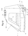
Figur 12- eine perspektivische Darstellung des Werkzeugs zum Verschließen von Umhüllungen beziehungsweise Kabelschläuchen wie flexible Rohrleitungen oder Behälterelemente mit zwei gegenüber liegend angeordneten beweglichen Werkzeugteilen, die die Schließelemente zusammenfügen,
Figur 13- Darstellung eines Kabelschlauchs
ähnlich wie Figur 14, wobei lediglich in dem oberen Raum eine Klebemasse eingebracht ist, Figur 14- ein weiteres Ausführungsbeispiel eines Kabelschlauchs mit Verschließelementen, die zusammengefügt sind und in deren Hohlräume eine Klebemasse einbringbar ist,
Figur 15- ein weiteres Arbeitswerkzeug mit einem Schweißtrafo,
Figur 16- ein weiteres Arbeitswerkzeug mit einem Klebstofftank.
- Figure 1
- 1 shows a schematic representation of the tool with a locking device and a device for securing the assembled closing elements by means of a trigger,
- Figure 2
- 2 shows a top view according to FIG. 1,
- Figure 3
- 2 shows a sectional illustration along the line CD according to FIG. 1,
- Figure 4
- 2 shows a sectional illustration along the line AB according to FIG. 1,
- Figure 5a + 5b
- a partial view of a zipper with the associated slide for closing the individual closing elements,
- Figure 6
- another embodiment of a tool with a pneumatic actuator,
- Figure 7
- various cables, which are put together to form a cable set and are sheathed by means of a cable hose,
- Figure 8 + 9
- two different functional sequences for creating a cable set and its sheathing,
- Figure 10
- a device for securing the assembled locking elements with a cable hose in section before the work of the associated stamp,
- Figure 11
- a fastening element or a clip which was inserted into the zipper by the stamp of the device for securing the assembled closing elements,
- Figure 12
- 1 shows a perspective view of the tool for closing envelopes or cable hoses such as flexible pipelines or container elements with two movable tool parts arranged opposite one another, which join the closing elements,
- Figure 13
- Representation of a cable hose similar to FIG. 14, only an adhesive being introduced in the upper space,
- Figure 14
- another embodiment of a cable hose with closure elements which are joined together and in the cavities of which an adhesive can be introduced,
- Figure 15
- another work tool with a welding transformer,
- Figure 16
- another work tool with an adhesive tank.
In der Zeichnung ist mit 24 ein Werkzeug bezeichnet,
das als Vorrichtung zum Verschließen von Umhüllungen,
wie Kabelschläuche 23, flexiblen Rohrleitungen oder Behälterelementen
dient.In the drawing, 24 denotes a tool,
that as a device for sealing envelopes,
such as
Das Werkzeug 24 besteht aus einem feststehenden Haltegriff
1 und einem mit dem Haltegriff 1 gelenkig verbundenen
Griff 2, der über einen Gelenkbolzen 15 mit dem
Haltegriff 1 schwenkbar verbunden ist. Der Haltegriff 1
weist ein Gehäuseteil 22 zur Aufnahme eines Displays 17
zur Wiedergabe von Zeichnungsteilen beziehungsweise
Dateninformationen, eine Einrichtung 29 zum Sichern zusammengefügter
Schließelemente 26 eines in Figur 5 dargestellten
Reißverschlusses 57 auf. Ferner ist im Gehäuseteil
22 ein Magazin 33 zur Aufnahme der Schließ-elemente
26 vorgesehen. Das Magazin 33 ist Bestandteil
der Einrichtung zum Sichern der zusammengefügten
Schließelemente 26. Die einzelnen Schließelemente beziehungsweise
Klammern 26, die in dem Magazin 33 aufgenommen
sind, werden mittels einer Spanneinrichtung 4
und einer in der Zeichnung nicht dargestellten Feder im
Magazin 33 in Richtung der Auslaßöffnung der Einrichtung
29 gedrückt. Die Einrichtung 29, die auch als
Tackervorrichtung bezeichnet werden kann, ist über
einen Gelenkbolzen 7 in dem Gehäuseteil 22 zwischen
einer Ausgangs- und einer Arbeitsstellung gegen die
Wirkung einer Feder 6 verschwenkbar aufgenommen. Der
Haltegriff 2 weist ferner ein Stellelement 58 auf, das
mit einer Auslösevorrichtung 55 in Wirkverbindung
steht, so daß bei Betätigung des Stellelements 58 die
Einrichtung 29 zum Sichern der zusammengefügten
Schließelemente 26 aktiviert wird und dadurch Befestigungselemente
beziehungsweise Klammern 62 mittels eines
Ambosses beziehungsweise Stempels 54 gemäß Figur 10 und
einer mit dem Stempel zusammenwirkenden Matrize 10 in
den Reißverschluß 57 eingesetzt werden, so daß die bereits
zusammengefügten Schließelemente 26 gegen Lösen
gesichert werden können.The
Die Befestigungselemente 62 können aus U-förmig ausgebildeten
Klammern bestehen, die mit ihren beiden Schenkeln
jeweils an der Rückseite der Schließelemente 26 in
den Kabelschlauch 23 eingedrückt und dann mittels des
Ambosses beziehungsweise der Matrize 10 gemäß Figur 11
umwinkelt werden. Der Amboß 10 kann an seinen beiden
sich gegenüberliegenden Enden mit einer Rundung versehen
sein, wobei die Rundung durch den Radius = R bestimmt
wird, der halb so groß ist wie die Dicke = D des
Ambosses, um dadurch den Kabelschlauch 23 vor Beschädigung
zu schützen. Der Radius R sollte zumindest zwischen
5 und 50 mm groß sein.The
Wie aus Figur 1 hervorgeht, ist an der Unterseite des
Gehäuseteils 22 gemäß Figur 3 und 4 ein Schieber 27
vorgesehen, der aus zwei gegenüberliegenden Wänden 51
gebildet ist und aus einem entsprechenden Mittelteil
besteht, über das die zusammengefügten Schließelemente
26 wieder auseinandergehakt werden können, wenn
der Schieber 27 gemäß Figur 5 nach unten bewegt wird.
Wird der Schieber 27 gemäß Figur 5 nach oben bewegt, so
werden die einander gegenüberliegenden Schließelemente
26 miteinander verhakt.As can be seen from Figure 1, is at the bottom of the
3 and 4, a
Gemäß Figur 1 wird die Einrichtung 29 mittels der Rückstellfeder
6 nach einem Tacker-Arbeitsvorgang in die in
Figur 1 dargestellte Position zurückverstellt und verharrt
in dieser Stellung so lange, bis das Stellelement
58 betätigt wird. Die Einrichtung 29 ist hierzu
über den Gelenkbolzen 7 im Gehäuseteil 22 schwenkbar
aufgenommen. Die Einrichtung 29 steht ferner über einen
Gelenkbolzen 63 mit dem Stellelement 58 in Wirkverbindung.
Sollen beispielsweise die Schließelemente 26 des
Reißverschlusses 57 gemäß Figur 5 zusammengefügt werden,
so wird der Schieber 27 nach oben bewegt. Hierzu
fährt eine Spreizzunge 64 sowie die Wände 51 des Schiebers
27, der am Haltegriff 1 fest angeordnet ist, durch
den Reißverschluß 57, so daß die gegenüberliegenden
Wände 51 des Schiebers 27 die jeweils gegenüberliegenden
Schließelemente 26 zusammenfügen und miteinander
verhaken. Hat beispielsweise der Schieber 27 von einem
Kabelsatz einen der gemäß Figur 7 dargestellten Knotenpunkte
zwischen 100 und 103 beziehungsweise das
Schließende 104 erreicht, so wird das Stellelement 58
betätigt und hierdurch die Einrichtung 29 aktiviert und
das entsprechende Schließelement 26 in den Kabelschlauch
23 eingeführt.According to Figure 1, the
In vorteilhafter Weise liegt der Stempel 54 der Einrichtung
29 dicht vor oder hinter dem Schieber 27 beziehungsweise
der zugehörigen Spreizzunge 64 zum Öffnen
der Schließelemente 26. Mittels der Spreizzunge 64 können,
wie bereits erwähnt, die Schließelemente 26 wieder
auseinandergehakt werden, wenn der Schieber 27 gemäß
Figur 5 nach unten verstellt wird.The
Gemäß Figur 6 kann das Werkzeug 24 beziehungsweise die
Einrichtung 29 zum Sichern der zusammengefügten
Schließ-elemente 26 des Reißverschlusses 57 mit einer
elektrischen, hydraulischen oder pneumatischen Stellvorrichtung
beziehungsweise einem Stellzylinder 21 in
Wirkverbindung stehen. Soll also die Einrichtung 29 aktiviert
werden, so wird hierzu der Stellzylinder 21
über Druckluft beaufschlagt, so daß der pneumatische
Stellzylinder mit der zugehörigen Auslösevorrichtung
aktiviert und der Stempel 54 gemäß Figur 10 nach unten
bewegt wird und dadurch die Befestigungselemente beziehungsweise
die Klammern 62 in den Kabelschlauch eingedrückt
werden. Ferner ist es möglich, daß dem Stellzylinder
oder auch dem Stempel 54 ein elektrischer beziehungsweise
optisch ansprechender Geber 56 (Figur 10)
zugeordnet ist, der nach Zurücklegen einer bestimmten
Wegstrecke des Werkzeugs 24 einen Stellimpuls auslöst,
beispielsweise dann, wenn die Knotenpunktstelle 101 erreicht
ist und dadurch ein Verstellen des Stempels 54
bewirkt wird. According to FIG. 6, the
Es ist auch vorteilhaft, daß der Einrichtung 29 zum
Sichern der zusammengefügten Schließelemente 26 eine
Meßvorrichtung 13 (Figur 1) beziehungsweise gemäß
Figur 8 ein Wegstreckenzähler 40 zugeordnet ist, der
den genauen Abstand zwischen zwei Knotenpunkten 101 und
102 beziehungsweise 102 und 103 erfaßt und nach Detektierung
dieser Knotenpunkte jeweils dann einen Stellimpuls
über den Geber 56 auslöst, wenn eine bestimmte
Wegstrecke zurückgelegt ist beziehungsweise der Geber
56 den Knotenpunkt 103 erreicht oder passiert hat.
Der Auslösevorgang einer Verschlußeinrichtung 25 beziehungsweise
der Einrichtung 29 kann also immer dann angesprochen
werden, wenn eine bestimmte Wegstrecke zurückgelegt
wurde oder, wie bereits erwähnt, der
Geber 56 eine entsprechende Knotenpunktstelle 102 beziehungsweise
103 passiert.It is also advantageous that the
Hierzu ist es besonders vorteilhaft, daß das Werkzeug
24 mit einer Einrichtung zur Erfassung verschiedener
Daten durch einen Kabelsatz 61 ausgestattet ist,
die mittels einer Stromversorgungseinrichtung 18 mit
Energie versorgt wird. Anstelle des in Figur 1 dargestellten
Displays 17 kann auch eine optische Warneinrichtung
oder eine Diode am Werkzeug 24 vorgesehen
sein, die dann anspricht, wenn eine bestimmte
Wegstrecke zurückgelegt ist beziehungsweise einer der
Knotenpunkte 101 beziehungsweise 102 oder 103 passiert
wurde.For this purpose, it is particularly advantageous that the
Eine weitere Verbesserung des Werkzeugs 24 wird auch
dadurch erreicht, daß in einer Datenbank verschiedene
Abmessungen von Kabelschlauchanordnungen 60 und den
verschiedenen Abzweigungen oder separaten Strängen oder
Wegstrecken erfaßt werden, so daß aufgrund dieser Daten
über den Rechner ein Kabelsatz mit seinen einzelnen Abzweigungen
für einen bestimmten Fahrzeugtyp erstellt
werden kann. Dieser Kabelsatz 61 kann dann auch auf
einem Bildschirm sichtbar gemacht oder über einen
Drucker ausgedruckt werden. Durch die erfindungsgemäße
Erfassung aller kabelsatzrelevanten Daten lassen sich
unterschiedliche Kabelsätze 61 erstellen, die gemäß
Kundenwunsch für einen bestimmten Fahrzeugtyp in Form
eines Ausdrucks der Bedienungsperson und dem Werkzeug
24 zugänglich gemacht werden.Another improvement to
In Figur 7 ist der bereits erwähnte Kabelsatz 61 dargestellt,
der aus einem Hauptkabelstrang 110 mit zahlreichen
abgezweigten Kabelsträngen 105, 106, 107, 108 und
109 bestehen kann, die nachstehend als Kabelabzweigungen
bezeichnet werden. Gemäß Figur 7 sind die einzelnen
Kabelabzweigungen 105 bis 109 vormontiert und mit je
einem Kabelschlauch 23 überzogen. Bisher wurden die
vorgefertigten Kabelabzweigungen auf einem mit Markierungselementen
versehenen Montagetisch abgelegt und
dann nach aufwendigen Meßarbeiten mit dem Hauptkabelstrang
110 verbunden. Nachdem diese Montagevorbereitung
getroffen wurde, mußte der Hauptkabelstrang 110 mit dem
Kabelschlauch 23 versehen werden. Hierzu wurde das
Werkzeug 24 eingesetzt. Aufgrund der erfindungsgemäßen
Ausbildung des Werkzeugs 24 ist es nun nicht mehr notwendig,
den Kabelstrang in der beschriebenen Weise zu
vermessen, zu montieren beziehungsweise fertigzustellen.FIG. 7 shows the cable set 61 already mentioned,
the one from a
Der Montageablauf beziehungsweise das Erstellen des
Kabelsatzes 61 ergibt sich aus den beiden Funktionsdarstellungen
gemäß Figur 8 und 9. In einer Datenbank 30
werden zuerst alle Funktionen beziehungsweise Kriterien
eines Kabelstrangs für die zu erstellenden Kraftfahrzeuge
erfaßt, beispielsweise wird in die Datenbank 30
eingegeben, welche Kabelstränge an die Lichtmaschine,
an das Schlußlicht, an die Steuerung oder Regelhydraulik
oder an den Airbag angeschlossen werden sollen.
Jedes Kraftfahrzeug kann zahlreiche Funktionsgruppen
aufweisen, die über die einzelnen Kabelstränge mit der
Stromversorgung 18 und den Steuer- beziehungsweise
Regeleinrichtungen verbunden sind. Sind derartige Daten
beziehungsweise Informationen über den Kabelsatz 61 erfaßt,
so können sie gemäß einer graphischen Aufbereitung
31 als Strukturbild dargestellt werden. Nach Ermittlung
des Kundenwunsches 32 wird der entsprechende
Kabelsatz abgerufen und in eine Produktionsplanung 34
eingebracht. Nun läßt sich anhand der ermittelten Funktionen
und der Kundenwünsche ein ganz spezieller Kabelsatz
gemäß Schaubild 35 zeichnerisch darstellen und im
einzelnen ein Kabelsatz 61 beziehungsweise der Hauptkabelstrang
110 als Grundmodul 36 festlegen. Steht der
Kabelsatz 61 fest, kann der Hauptkabelstrang 110 mit
dem Kabelschlauch 23 versehen werden. Hierzu wird das
Werkzeug 24 in den Kabelschlauch 23 eingesetzt und fügt
die einzelnen Schließelemente 26 zusammen. Hierzu fährt
das Werkzeug 24 den Hauptkabelstrang 110 entlang, bis
es an eine entsprechende Knotenpunktstelle, beispielsweise
101, gelangt. Da das Werkzeug mit einem Geber 56
und der Meßvorrichtung 13 ausgestattet ist, wird die
Bedienungsperson nach Zurücklegen dieser Wegstrecke
entweder optisch oder akustisch über eine Anzeigevorrichtung,
beispielsweise über das Display 17, informiert
und kann jetzt den ersten Kabelstrang 105 mit dem
Hauptkabelstrang 110 verbinden oder aus dem Schlauch 23
herausführen, wenn der Kabelstrang 105 bisher parallel
zum Hauptkabelstrang 110 verlaufend verlegt wurde. Im
Bereich des Knotenpunkts 101 wird gemäß der graphischen
Darstellung (gemäß Figur 8 bei 39) mittels des Werkzeugs
24 und der Einrichtung 29 zum Sichern der zusammengefügten
Schließelemente 26 die Klammer 62 in den
Kabelschlauch 23 eingesetzt, so daß nach diesem Arbeitsvorgang
die Schließelemente 26 nicht mehr auseinandergehakt
werden können. In vorteilhafter Weise wird
vor und nach dem Knotenpunkt 101 ein derartiges Sicherungselement
beziehungsweise eine Klammer 62 eingesetzt.
Sollen derartige Klammern 62 nachträglich wieder
gelöst werden, so können sie durch eine in der Zeichnung
nicht dargestellte Aushebevorrichtung, die am
Werkzeug 24 vorgesehen sein kann, wieder entfernt werden,
ohne daß dabei der Kabelschlauch 23 beschädigt
wird.The assembly process or the creation of the
Cable set 61 results from the two functional representations
according to FIGS. 8 and 9. In a
Das Werkzeug 24 wird nach Ausführung vorstehend beschriebener
Arbeitsvorgänge weiter durch den Kabelschlauch
23 geführt, und die Bedienungsperson erhält
über das Display 17 beziehungsweise gemäß Figur 8 über
eine Wegstreckenanzeige 41 eine weitere Information, um
die gleichen Arbeitsvorgänge wie an der Knotenpunktstelle
101 durchführen zu können.
Hat die Bedienungsperson mit dem Werkzeug 24 ein
Schließende 42 beziehungsweise die Knotenpunktstellen
100 bis 103 erreicht, so wird sie entsprechend informiert
und kann nun den Arbeitsvorgang abschließen
und die Endstücke 43 des Kabelschlauchs 23 ebenfalls
sichern.Has the operator with the
Wurde beispielsweise (Position 43) versehentlich an einer Stelle gemäß den in Figur 9 dargestellten Arbeitspositionen ein Arbeitsvorgang oder Tackervorgang falsch ausgeführt, so läßt sich der Fehler durch einen entsprechenden Verfahrensschritt korrigieren oder rückgängig machen und der Arbeitsvorgang kann wiederholt werden, ohne daß dadurch der gesamte Arbeitsablauf gemäß des erfindungsgemäßen Verfahrens beeinträchtigt wird.For example, (position 43) was accidentally on a position according to the working positions shown in Figure 9 an operation or stapling operation executed incorrectly, the error can be correct or undo the corresponding procedural step make and the operation can be repeated without the entire workflow impaired the inventive method becomes.
Falls ein nachträglicher Einbau (vergl. Öffnen 44 gemäß
Figur 8) eines Kabelstrangs, beispielsweise 106, erforderlich
wird, kann mittels des Werkzeugs 24 der Kabelschlauch
nochmals geöffnet werden und, um danach den
Kabelstrang 106 mit dem Hauptkabelstrang 110 zu verbinden,
können die entsprechenden Klammern 62 entfernt
werden. Nach Abschluß aller Arbeiten wird das Ende 45
aller Arbeitsgänge auf dem Display 17 angegeben, so daß
die Bedienungsperson weiß, daß der Kabelsatz 61 fertiggestellt
ist.If retrofitting (see opening 44 according to
Figure 8) of a cable harness, for example 106, required
is, by means of the
Gemäß Figur 9 kann der Arbeitsablauf zum Erstellen des
Kabelsatzes 61 weiter verbessert werden. Werden gemäß
Figur 8 alle Daten eines Kabelsatzes entsprechend erfaßt,
können diese mittels einer CAD-Anlage 46 aufbereitet
und bei 47 gemäß Figur 9 bereitgestellt werden,
um somit die Produktionsreihenfolge (Server) 48 der
einzelnen Kabelsätze 61 festzulegen. Der Transfer der
Daten 49 aus dem Server 48 an das Werkzeug 24 kann per
Funk, Diskette oder Eprom übermittelt werden. Auf diese
Weise erhält man eine optimale Steuerung des Werkzeugs
24 beim Erstellen eines Kabelsatzes 61. Die einzelnen
Informationen können von der Bedienungsperson
auf dem Display 17 abgelesen werden (vergl. Info
Schließen 50 gemäß Figur 8). Nach Zurücklegen einer bestimmten
Wegstrecke wird die Bedienungsperson mittels
Display 17 (gemäß Wegstreckenanzeige 52 nach Figur 9)
über ein akustisches Signal oder über eine LED-Anzeige
entsprechend informiert, was zu tun ist beziehungsweise
ob eine weitere Sicherung des Reißverschlusses 57 erfolgen
soll beziehungsweise gemäß 45 alle Arbeiten zum
Erstellen des Kabelsatzes 61 durchgeführt sind (vergl.
Ende 45 gemäß Figur 8). Alle nicht erwähnten Arbeitsvorgänge
zum Erstellen eines Kabelsatzes 61 sind in der
Beschreibung der Figur 8 erwähnt.According to Figure 9, the workflow for creating the
Cable set 61 can be further improved. According to
8 shows all the data of a cable set,
can be processed using a
Der in Figur 14 dargestellte Kabelschlauch beziehungsweise
die Umhüllung dient zur Aufnahme von Teilen, wie
z.B. Kabeln, elektrischen Teilen oder anderen elekrischen
Teilen, die vor Feuchtigkeit oder Spritzwasser
geschützt werden sollen. Die Umhüllung beziehungsweise
der Kabelschlauch 23' kann gemäß den Figuren 13 und 14
aus zwei nach außen gewölbt geformten Seitenwänden bestehen,
die über ein mit Bezug auf die Figuren 13 und
14 horizontal verlaufendes Wandteil verbunden sind. In
den seitlichen, gegenüberliegenden Wandteilen der Umhüllung
23' beziehungsweise in dem horizontal verlaufenden
Wandteil befindet sich ein Dehnteil 122, so daß
bei übermäßig starkem Druck der Querschnitt bei Aufnahme
der Kabelteile verändert werden kann und sich somit
besser der Außenkontur der einzelnen Kabelelemente
anpaßt. Das Dehnteil 122 kann beispielsweise ziehharmonika-artig
ausgebildet sein. Es ist jedoch auch möglich,
das Dehnteil 122 in einem bestimmten Bereich Z-förmig
auszubilden, so daß sich dieser Bereich bei
stärkerem Druck soweit dehnt, bis sich eine durchgehende
einteilige, nicht gefaltete Wand bildet.The cable hose shown in Figure 14 or
the envelope serves to hold parts such as
e.g. Cables, electrical parts or other electrical
Share that from moisture or splashing water
should be protected. The wrapping respectively
the cable hose 23 'can be according to FIGS. 13 and 14
consist of two curved side walls,
the one with reference to Figures 13 and
14 horizontally extending wall part are connected. In
the lateral, opposite wall parts of the casing
23 'or in the horizontal
Wall part is an
Anstelle des Kabelschlauchs und des dort dargestellten Dehnteils kann auch der Kabelschlauch selbst aus einem dehnbaren Material hergestellt sein, das sich den Außenkonturen der im Kabelschlauch angeordneten Teile anpaßt.Instead of the cable hose and the one shown there The cable hose itself can also be expanded from one be made of stretchable material that the Outer contours of the parts arranged in the cable hose adjusts.
Gemäß Figur 13 sind die beiden gegenüberliegenden Wandteile
mit ihren entsprechenden Enden 121 an zwei gegenüberliegende
Schließelemente 113 fest angeschlossen.
Das Ende des Wandteils 121 kann beispielsweise über
eine thermische Verbindung oder auch über eine Klebeverbindung
mit dem Schließelement 113 fest verbunden
werden.According to Figure 13, the two opposite wall parts
with their
Gemäß Figur 13 bestehen die beiden zusammenfügbaren
Schließelemente 113 aus einem Paßelement beziehungsweise
hakenförmig ausgebildeten Federelement 115, das
in eine entsprechende, der Kontur des Federelements angepaßte
Nut 116 eingeschoben wird, wenn hierzu das
Werkzeug 24 mit entsprechenden Gleitelementen 112 gegen
die Rückseite der beiden gegenüberliegenden Schließelemente
113 gedrückt wird. Hierzu kann die Rückseite 113
in etwa V-förmig ausgebildet sein, in die die Gleitelemente
112 hineingedrückt werden und die dann an der
Außenkontur der Gleitelemente 112 entlangfahren, so daß
bei diesem Arbeitsvorgang die Schließelemente 113 ineinandergefügt
werden und damit eine feste Verbindung
untereinander herstellen.According to FIG. 13, the two can be joined together
Closing
Oberhalb der zusammengefügten Schließelemente 113 befindet
sich eine Lasche 123, die zumindest beim Arbeitsbeginn
an einem Schließelement, gemäß Figur 3 an
dem linken Schließelement 113, fest angeschlossen ist.
Diese Lasche 123 überlagert die gesamte obere Fläche
der beiden zusammengefügten Schließelemente 113 und
überdeckt dabei eine Nut beziehungsweise einen Zwischenraum
117, der zwischen den Flächen 118 gebildet
wird. Die zusammengefügten gegenüberliegenden Klebeflächen
118 weisen untereinander einen Abstand auf, so daß
in diesen Zwischenraum beziehungsweise in diese Nut 117
eine Klebemasse 119 eingebracht werden kann. Die Klebemasse
119 wird gemäß Figur 14 über ein Spritzwerkzeug
zugeführt. In Figur 14 ist lediglich die Spritzdüse 120
des nicht weiter dargestellten Spritzwerkzeugs abgebildet.
Die Klebemasse 119 wird in die obere Nut 117 eingefügt
und schließt damit den Innenraum des Kabelschlauchs
23' dichtend ab, so daß kein Spritzwasser beziehungsweise
keine Feuchtigkeit in den Innenraum des
Kabelschlauchs 23' eindringen kann. Soll der Kabelschlauch
absolut wasserdicht sein, so muß hierzu die
Wandung des Kabelschlauchs entsprechend ausgelegt werden,
damit sie einem entsprechenden Druck standhalten
kann.Is located above the assembled closing elements 113
a
Anstelle der in Figur 14 dargestellten Klebemasse 119
kann auch nur die Lasche 123 eine feste und dichte Verbindung
zwischen den beiden Schließelementen 113 herstellen.
Die Lasche 123 kann beispielsweise mit der
Schweißfläche 124 des rechten Schließelements 113 über
eine Klebemasse verbunden werden. Es ist jedoch auch
möglich, die Lasche 123 über ein Ultraschweißverfahren
mit der Schweißfläche 124 dichtend zu verbinden. Hierzu
wird ein entsprechendes, in Figur 13 lediglich schematisch
angedeutetes Schweißwerkzeug 111 eingesetzt, das
eine Ultraschweißverbindung zwischen den Klebeflächen
herstellt.Instead of the adhesive 119 shown in FIG. 14
can only the tab 123 a tight and tight connection
produce between the two closing
Anstelle einer Ultraschweißverbindung ist auch eine
thermische Verbindung zwischen den einzelnen Klebeflächen
der Schließelemente 113 möglich. Hierzu wird die
Oberfläche der entsprechenden Teile so weit erhitzt,
bis eine Klebeverbindung zwischen den einzelnen zu verbindenden
Teilen hergestellt wird. Es ist also auch
möglich, das Werkzeug 111 als Heizelement auszubilden,
das die entsprechenden Stellen soweit erhitzt, bis die
gewünschte Klebeverbindung zwischen den zu verbindenden
Teilen hergestellt ist.Instead of an ultrasonic welding connection there is also one
thermal connection between the individual adhesive surfaces
of the
In Figur 13 sind die Wände 112 des Schiebers 51' V-förmig ausgebildet. Es ist jedoch auch möglich, die Wände ballig auszubilden, wobei die entsprechenden Gegenstücke der Wände der Schließelemente 113 eine entsprechend angepaßte Kontur aufweisen.In Figure 13, the walls 112 of the slide 51 'are V-shaped educated. However, it is also possible to use the walls form spherical, the corresponding counterparts the walls of the closing elements 113 a corresponding have an adapted contour.
Gemäß Figur 14 verläuft das Dehnteil 122 zickzackförmig
Verlauf mit entsprechenden Vertiefungen, die einen Winkel
α beziehungsweise β aufweisen, der zwischen 45° und
110° oder in vorteilhafter Weise zwischen 50° und 95°
betragen kann.According to FIG. 14, the
Im Ausführungsbeispiel gemäß Figur 14 sind vier hintereinander
angeordnete Vertiefungen durch den zickzackförmigen
Verlauf des Dehnteils 122 abgebildet. Je nach
Querschnittsgröße kann das Dehnteil auch verlängert
werden und weist dann eine entsprechend größere Anzahl
von Vertiefungen auf.In the exemplary embodiment according to FIG. 14 there are four in a row
arranged depressions through the zigzag
Course of the
Das im unteren Wandteil vorgesehene Dehnteil 122 kann
auch in die Seitenteile der Wandelemente der Umhüllung
integriert werden. Die hierdurch vorteilhaft ausgebildete
Umhüllung beziehungsweise der Kabelschlauch 23'
mit den ohne weiteres zusammenfügbaren Schließelementen
läßt sich durch das entsprechende Werkzeug in kurzer
Zeit ohne großen Kraftaufwand sehr exakt montieren. The
Soll beispielsweise der Kabelschlauch 23, 23' wieder
geöffnet werden, so müssen lediglich die einzelnen Verschlußelemente
oder die Klebeverbindung entfernt werden,
um dann die Schließelemente außeinander zu nehmen.
Das Öffnen des Kabelschlauchs 23 läßt sich insbesondere
dann besonders leicht vornehmen, wenn keine Klebeverbindung
sondern lediglich eine zusammensteckbare beziehungsweise
ineinanderfügbare Verbindung gewählt wird.For example, if the
Gemäß den Figuren 12, 15 und 16 kann das Werkzeug 24
mit Bedienungselementen 129 ausgestattet sein, die im
Griff 2 integriert sind und in Verbindung mit einem
nicht dargestellten Rechner am Werkzeug eine Steuerfunktion
auslösen, so daß - wie eingangs beschrieben -
der Kabelschlauch 23' zusammengefügt wird.According to FIGS. 12, 15 and 16, the
Die einzelnen Verbindungselemente 26 können gemäß
Figur 16 mittels eines in einem Klebstofftank 128 vorgesehenen
Klebers verbunden werden. Ferner ist es möglich,
die Verbindungselemente 26 mittels eines Schweißtrafos
(Figur 15) zu verbinden.The
Claims (34)
- A device to close sheathings, such as cable conduits (23), flexible pipelines or container elements by means of a closure device (25) provided on a tool (24), whereby closure elements (26) at two rim parts of the sheathing located opposite each other can be alternatingly hooked together and unhooked, or separated, when being opened by means of a slider (27) disposed on the tool (24), characterized in that an additional device (29) for securing the connected closure elements or connecting elements (26), which can be activated independently of the respective position of the slider (27), is provided on the tool (24) for receiving the slider (27).
- The device in accordance with claim 1, characterized in that the device (29) for securing the connected closure elements (26) is situated in the area of the slider.
- The device in accordance with claim 1 or 2, characterized in that the device (29) for securing the connected closure elements (26) or the zipper (57) is situated in front of or behind the slider (27) with respect to the direction of movement of the slider (27).
- The device in accordance with claim 1, characterized in that the device (29) is made up of a plunger (54) affixed on the tool (24) or of an anvil or a matrix (10) interacting with it, which can be activated by means of a regulating element (58).
- The device in accordance with one or several of the preceding claims, characterized in that the device (29) for securing the connected closure elements (26) is made up of a plunger (54) affixed on the tool (24) or of an anvil or a matrix (10) interacting with it, whereby the device (29) can be activated by means of a regulating element (58) which interacts with a transmitter (56) that triggers a regulating pulse after the tool (24) has traveled a defined distance and causes a displacement of the plunger (54).
- The device in accordance with one or several of the preceding claims, characterized in that the device (29) for securing the connected closure elements (26) of a zipper (57) is operatively connected to a hydraulic, pneumatic or electric regulating device (21), which is operatively connected to the regulating element (58) and/or with the plunger (54).
- The device in accordance with one or several of the preceding claims, characterized in that the device (29) for securing the connected closure elements (26) consists of a hydraulic or pneumatic regulating cylinder (21), which is operatively connected to a trigger device (55) of the plunger (54).
- The device in accordance with claim 1, characterized in that a measuring device (13) is associated with the closure device (25) and/or with the device (29) for securing the connected closure elements (26), which can be connected to a computer.
- The device in accordance with claim 1, characterized in that the measuring device (13) consists of a measuring wheel or a pulse transmitter which detects a distance traveled by the tool (24) and, at a defined point, forwards regulating information to a transmitter (56), which causes a displacement of the plunger (54).
- The device in accordance with claim 1, characterized in that the measuring device (13), the closure device (25) and the device for securing the connected closure elements (26) are combined in one component.
- The device in accordance with claim 1, characterized in that the measuring device (13), the closure device (25) and the device for securing the connected closure elements (26) are combined in an electrical module.
- The device in accordance with claim 1, characterized in that the measuring device (13), the closure device (25) and the device for securing the connected closure elements (26) are combined in an electrical module, whereby the measuring device (13), the closure device (25) and the device for securing the connected closure elements (26) are operatively connected to an electrical control device (59).
- The device in accordance with claim 1, characterized in that the computer (30) is part of the control device (59), whose control program stored in a database can control the device (29) for securing the connected closure elements (26) as a function of a distance traveled by the tool (24).
- The device in accordance with claim 1, characterized in that the tool (24) is equipped with a device for recording various data about a cable set (61) and is connected to a current supply source (18).
- The device in accordance with claim 1, characterized in that the tool (24) is equipped with an acoustical and/or optical indicator device or display (17).
- The device in accordance with one or several of the preceding claims, characterized in that the tool (24) has an unlocking device which can be controlled via the transmitter (56) and unlocks the closure elements (29) if a further branch (106) is to be added to a produced cable bundle (61) or is to be connected to the main cable branch (110).
- The device in accordance with claim 2, characterized in that the tool (24) is equipped with several devices (29) for securing the clips (62).
- The device in accordance with claim 5, characterized in that the anvil (10) can be provided with a curvature on its two opposite ends.
- The device in accordance with claim 5, characterized in that the curvature is determined by the radius (R) that is half the thickness (D) of the anvil (10).
- The device in accordance with claim 5, characterized in that the radius (R) has a value between 1 mm and 50 mm.
- A sheathing produced with the device of claim 1, characterized in that the sheathing created by means of this device or the cable conduit (23) has, as closure elements (26), a zipper (57) with intermeshing teeth or connectable tongue-and-groove elements (114, 115) or connecting elements, which lie against each other and can be glued or welded together.
- The sheathing produced with the device of claim 1, characterized in that the fitted spring (115) is designed as a hook which can be inserted into the groove (114).
- The sheathing produced with the device of claim 1, characterized in that the connecting elements of the closure element (26) located opposite each other can be connected by means of an adhesive.
- The sheathing produced with the device of claim 1, characterized in that the connecting elements of the closure element (26) located opposite each other can be thermally connected to each other.
- The sheathing produced with the device of claim 1, characterized in that the connecting elements located opposite each other have surfaces which can be brought into contact with each other and to which the adhesive can be applied.
- The sheathing produced with the device of claim 1, characterized in that the connecting elements (26) located opposite each other are treated on their surfaces located opposite each other in such a way that they form a secure connection with each other.
- The sheathing produced with the device of claim 1, characterized in that the sheathing (23) has expansion elements (122) for changing its cross section.
- A process for closing sheathings, such as cable conduits (23), flexible pipelines or container elements, suitable for a device in accordance with claim 1, characterized in that the closure elements (26) are first connected to each other by means of the tool (24) and are securely connected to each other by means of a device (29) for securing the connected closure elements (26), whereby one, two or several closure elements (26) can be inserted into the cable conduit in the area of the cable junction (101).
- The process for closing sheathings, such as cable conduits (23), flexible pipelines or container elements, suitable for a device in accordance with claim 1, characterized in that various dimensions of cable conduit arrangements (60) and various branches (105 to 109) or separate bundles (100 to 103) and/or the distances between two junctions of cable conduit arrangements (60) are stored in a database (30) and can be made available to the control device (59) of the tool (24).
- The process suitable for a device in accordance with claim 1 or 15, characterized by the following process steps:a. Entry of the key number of a defined car type in accordance with customer specifications into the database (30),b. Selection of a cable set (61) in accordance with the car type and customer specifications (32),c. Determination of the sequence of the vehicles (34) to be assembled in a defined sequence from 1 to n,d. Closure of the zipper by means of the tool (24),e. Determination of the distance between two junctions (100 and 101) of the cable set (61),f. Securing the closure elements (26) of the zipper (57) by means of the device (29).
- The process suitable for a device in accordance with claim 1 or 15, characterized by the following process steps:a. Entry of the key number of a defined car type in accordance with customer specifications into the database (30),b. Selection of a cable set (61)in accordance with the car type and customer specifications (32),c. Determination of the sequence of the vehicles (34) to be assembled in a defined sequence from 1 to n,d. Preparation of a drawing (35) of the cable set (61) and reproducing it on a display (38),e. Closure of the zipper by means of the tool (24),f. Determination of the distance between two junctions (100 and 101) of the cable set (61),g. Securing the closure elements (26) of the zipper (57) by means of the device (29).
- The process suitable for a device in accordance with claim 1 or 15, characterized in that the information about a cable set (61) for a defined car type stored in the database (30) is processed graphically (31) and is displayed on a screen and/or printed out as a drawing.
- The process suitable for a device in accordance with claim 1 or 15, characterized in that the information about a cable set (61) for a defined car type stored in the database (30) is processed after the entry of a defined numerical characteristic of a car type along with the determination of the individual distances between two junctions and this information is then processed graphically (31) and made available to production planning (34).
- The process suitable for a device in accordance with claim 1 or 15, characterized in that, in the area of a junction (101) in front of and/or behind the junction and/or in the area of a closure element, the closure elements (26) that are locked together by means of the tool (24) are secured by a fastening element or a clip (62) which is inserted by means of the device (29) between two closure elements (29) located opposite each other.
Applications Claiming Priority (5)
| Application Number | Priority Date | Filing Date | Title |
|---|---|---|---|
| DE4425257 | 1994-07-16 | ||
| DE4425257 | 1994-07-16 | ||
| DE19519849 | 1995-05-31 | ||
| DE19519849A DE19519849C1 (en) | 1994-07-16 | 1995-05-31 | Device for closing envelopes such as cable conduits |
| PCT/EP1995/002368 WO1996002967A1 (en) | 1994-07-16 | 1995-06-19 | Device for closing sheathings such as cable conduits |
Publications (2)
| Publication Number | Publication Date |
|---|---|
| EP0771485A1 EP0771485A1 (en) | 1997-05-07 |
| EP0771485B1 true EP0771485B1 (en) | 1998-02-04 |
Family
ID=25938436
Family Applications (1)
| Application Number | Title | Priority Date | Filing Date |
|---|---|---|---|
| EP95924283A Expired - Lifetime EP0771485B1 (en) | 1994-07-16 | 1995-06-19 | Device for closing sheathings such as cable conduits |
Country Status (9)
| Country | Link |
|---|---|
| US (1) | US6154943A (en) |
| EP (1) | EP0771485B1 (en) |
| JP (1) | JPH10505284A (en) |
| CN (1) | CN1084942C (en) |
| AT (1) | ATE163109T1 (en) |
| BR (1) | BR9506942A (en) |
| ES (1) | ES2112065T3 (en) |
| TR (1) | TR199500839A2 (en) |
| WO (1) | WO1996002967A1 (en) |
Families Citing this family (7)
| Publication number | Priority date | Publication date | Assignee | Title |
|---|---|---|---|---|
| US8960520B2 (en) * | 2007-10-05 | 2015-02-24 | Covidien Lp | Method and apparatus for determining parameters of linear motion in a surgical instrument |
| CN104824925B (en) * | 2015-05-28 | 2017-11-17 | 福建浔兴拉链科技股份有限公司 | A kind of quick zipper hinge of slide fastener |
| AT518545B1 (en) * | 2016-10-17 | 2017-11-15 | Blum Gmbh Julius | furniture drive |
| CN112436443A (en) * | 2020-11-19 | 2021-03-02 | 中建八局轨道交通建设有限公司 | Auxiliary structure for pulling cable and pulling method thereof |
| WO2023237775A1 (en) * | 2022-06-10 | 2023-12-14 | Gustav Klauke Gmbh | Hand tool |
| WO2023237776A1 (en) * | 2022-06-10 | 2023-12-14 | Gustav Klauke Gmbh | Hand tool |
| CN116453751B (en) * | 2023-03-31 | 2024-06-04 | 江苏赛特电气有限公司 | Comprehensive protection B1-level flame-retardant cable for rail transit |
Family Cites Families (7)
| Publication number | Priority date | Publication date | Assignee | Title |
|---|---|---|---|---|
| US2666916A (en) * | 1950-11-02 | 1954-01-26 | Spiegel William | Combined stretching and stapling device |
| DE1046539B (en) * | 1956-09-14 | 1958-12-18 | Opti Werk G M B H & Co | Coil spring zipper made of plastic for closing slits in bed sheets, pillow cases, etc. like |
| US3650009A (en) * | 1968-08-15 | 1972-03-21 | Flexigrip Inc | Zippertubing closing tool |
| US4224731A (en) * | 1978-09-15 | 1980-09-30 | Hartco Company | Method of and apparatus for applying pronged sheet metal spring anchoring clips to furniture rails |
| US4218814A (en) * | 1979-04-09 | 1980-08-26 | Dart Industries Inc. | Method of insulating conduit |
| US4891256A (en) * | 1983-04-26 | 1990-01-02 | The Bentley-Harris Manufacturing Co. | Wraparound closure device and a method of making same |
| US5208962A (en) * | 1992-02-04 | 1993-05-11 | Tag-Matic, Inc. | Method and apparatus for affixing tags on lumber |
-
1995
- 1995-06-19 WO PCT/EP1995/002368 patent/WO1996002967A1/en active IP Right Grant
- 1995-06-19 AT AT95924283T patent/ATE163109T1/en active
- 1995-06-19 US US08/702,662 patent/US6154943A/en not_active Expired - Lifetime
- 1995-06-19 EP EP95924283A patent/EP0771485B1/en not_active Expired - Lifetime
- 1995-06-19 CN CN95192221A patent/CN1084942C/en not_active Expired - Lifetime
- 1995-06-19 BR BR9506942A patent/BR9506942A/en not_active IP Right Cessation
- 1995-06-19 JP JP8504623A patent/JPH10505284A/en active Pending
- 1995-06-19 ES ES95924283T patent/ES2112065T3/en not_active Expired - Lifetime
- 1995-07-10 TR TR95/00839A patent/TR199500839A2/en unknown
Also Published As
| Publication number | Publication date |
|---|---|
| CN1144575A (en) | 1997-03-05 |
| TR199500839A2 (en) | 1996-06-21 |
| WO1996002967A1 (en) | 1996-02-01 |
| US6154943A (en) | 2000-12-05 |
| EP0771485A1 (en) | 1997-05-07 |
| CN1084942C (en) | 2002-05-15 |
| JPH10505284A (en) | 1998-05-26 |
| ATE163109T1 (en) | 1998-02-15 |
| ES2112065T3 (en) | 1998-03-16 |
| BR9506942A (en) | 1997-09-09 |
Similar Documents
| Publication | Publication Date | Title |
|---|---|---|
| DE19633894C2 (en) | Device for actuating a lock installed in a door, a flap or the like, in particular in a vehicle | |
| WO2014186911A1 (en) | Strapping device having a display and operating apparatus | |
| EP0771485B1 (en) | Device for closing sheathings such as cable conduits | |
| EP2640612A1 (en) | Wiper blade arrangement and connecting arrangement having a wiper blade arrangement and a wiper arm | |
| EP1013554A1 (en) | Method and apparatus for the automatic bundling of cable strands | |
| EP1793151A1 (en) | Line-coupling | |
| DE102011102521A1 (en) | Liner part for inner space i.e. passenger side dashboard, of car, has connecting part including loop made of flexible material and provided between mounting portions of connecting part such that airbag coverage area is supported by loop | |
| DE3828595C2 (en) | ||
| DE202008003757U1 (en) | Rotary connection coupling | |
| WO2019206748A1 (en) | Binding device and method for automatically bundling cable strands | |
| CH699404A1 (en) | Energy coupling, and coupling with energy coupling. | |
| DE202005021619U1 (en) | filter bag | |
| DE19519849C1 (en) | Device for closing envelopes such as cable conduits | |
| EP0583618B1 (en) | Sun visor for vehicles | |
| AT393817B (en) | BONNET, ESPECIALLY FOR A COMMERCIAL VEHICLE | |
| EP1285296B1 (en) | Device for actuating the flap of optical waveguide splicers | |
| DE1958989A1 (en) | Continuous welding of edges of plastics films - using hot air to weld and pre heat the edges | |
| DE69710831T2 (en) | Heater for heat sealing container bottom parts | |
| EP2152974B1 (en) | Coupling for machine tools | |
| DE102013107902B4 (en) | Wind deflector for a vehicle and vehicle with a wind deflector | |
| DE2639361B2 (en) | DEVICE FOR TENSIONING A MOBILE SCREENING MACHINE FOR DRIVING UNDERGROUND ROADS | |
| DE10353009B4 (en) | Sliding roof with at least two covers for vehicles | |
| DE19816652B4 (en) | Shopping cart, in particular children shopping cart, with flagpole | |
| DE3311220A1 (en) | Operating device for the parking brake of a motor vehicle | |
| DE10259313B3 (en) | Molded part for holding and stiffening a tab-shaped cutout part in a flat good |
Legal Events
| Date | Code | Title | Description |
|---|---|---|---|
| PUAI | Public reference made under article 153(3) epc to a published international application that has entered the european phase |
Free format text: ORIGINAL CODE: 0009012 |
|
| 17P | Request for examination filed |
Effective date: 19961025 |
|
| AK | Designated contracting states |
Kind code of ref document: A1 Designated state(s): AT ES FR GB IT NL |
|
| GRAG | Despatch of communication of intention to grant |
Free format text: ORIGINAL CODE: EPIDOS AGRA |
|
| 17Q | First examination report despatched |
Effective date: 19970530 |
|
| GRAG | Despatch of communication of intention to grant |
Free format text: ORIGINAL CODE: EPIDOS AGRA |
|
| GRAH | Despatch of communication of intention to grant a patent |
Free format text: ORIGINAL CODE: EPIDOS IGRA |
|
| GRAH | Despatch of communication of intention to grant a patent |
Free format text: ORIGINAL CODE: EPIDOS IGRA |
|
| ITF | It: translation for a ep patent filed | ||
| GRAA | (expected) grant |
Free format text: ORIGINAL CODE: 0009210 |
|
| AK | Designated contracting states |
Kind code of ref document: B1 Designated state(s): AT ES FR GB IT NL |
|
| REF | Corresponds to: |
Ref document number: 163109 Country of ref document: AT Date of ref document: 19980215 Kind code of ref document: T |
|
| GBT | Gb: translation of ep patent filed (gb section 77(6)(a)/1977) |
Effective date: 19980211 |
|
| REG | Reference to a national code |
Ref country code: ES Ref legal event code: FG2A Ref document number: 2112065 Country of ref document: ES Kind code of ref document: T3 |
|
| ET | Fr: translation filed | ||
| PLBE | No opposition filed within time limit |
Free format text: ORIGINAL CODE: 0009261 |
|
| STAA | Information on the status of an ep patent application or granted ep patent |
Free format text: STATUS: NO OPPOSITION FILED WITHIN TIME LIMIT |
|
| 26N | No opposition filed | ||
| REG | Reference to a national code |
Ref country code: GB Ref legal event code: IF02 |
|
| PGFP | Annual fee paid to national office [announced via postgrant information from national office to epo] |
Ref country code: GB Payment date: 20140618 Year of fee payment: 20 |
|
| PGFP | Annual fee paid to national office [announced via postgrant information from national office to epo] |
Ref country code: NL Payment date: 20140618 Year of fee payment: 20 Ref country code: ES Payment date: 20140624 Year of fee payment: 20 Ref country code: AT Payment date: 20140611 Year of fee payment: 20 |
|
| PGFP | Annual fee paid to national office [announced via postgrant information from national office to epo] |
Ref country code: FR Payment date: 20140619 Year of fee payment: 20 |
|
| PGFP | Annual fee paid to national office [announced via postgrant information from national office to epo] |
Ref country code: IT Payment date: 20140630 Year of fee payment: 20 |
|
| REG | Reference to a national code |
Ref country code: NL Ref legal event code: V4 Effective date: 20150619 |
|
| REG | Reference to a national code |
Ref country code: GB Ref legal event code: PE20 Expiry date: 20150618 |
|
| PG25 | Lapsed in a contracting state [announced via postgrant information from national office to epo] |
Ref country code: GB Free format text: LAPSE BECAUSE OF EXPIRATION OF PROTECTION Effective date: 20150618 |
|
| REG | Reference to a national code |
Ref country code: AT Ref legal event code: MK07 Ref document number: 163109 Country of ref document: AT Kind code of ref document: T Effective date: 20150619 |
|
| REG | Reference to a national code |
Ref country code: ES Ref legal event code: FD2A Effective date: 20150925 |
|
| PG25 | Lapsed in a contracting state [announced via postgrant information from national office to epo] |
Ref country code: ES Free format text: LAPSE BECAUSE OF EXPIRATION OF PROTECTION Effective date: 20150620 |