EP0771094B1 - Verfahren und Anordnung zur Herstellung und Erkennung der Authentizität von Befehlssignalen - Google Patents
Verfahren und Anordnung zur Herstellung und Erkennung der Authentizität von Befehlssignalen Download PDFInfo
- Publication number
- EP0771094B1 EP0771094B1 EP96250243A EP96250243A EP0771094B1 EP 0771094 B1 EP0771094 B1 EP 0771094B1 EP 96250243 A EP96250243 A EP 96250243A EP 96250243 A EP96250243 A EP 96250243A EP 0771094 B1 EP0771094 B1 EP 0771094B1
- Authority
- EP
- European Patent Office
- Prior art keywords
- signal
- circuit
- transmission circuit
- automaton
- reception circuit
- Prior art date
- Legal status (The legal status is an assumption and is not a legal conclusion. Google has not performed a legal analysis and makes no representation as to the accuracy of the status listed.)
- Expired - Lifetime
Links
- 238000000034 method Methods 0.000 title claims description 17
- 230000005540 biological transmission Effects 0.000 claims description 45
- 230000008878 coupling Effects 0.000 claims description 20
- 238000010168 coupling process Methods 0.000 claims description 20
- 238000005859 coupling reaction Methods 0.000 claims description 20
- 230000008569 process Effects 0.000 claims description 7
- 230000007704 transition Effects 0.000 claims description 6
- 238000011156 evaluation Methods 0.000 claims description 5
- 238000012986 modification Methods 0.000 claims description 5
- 230000004048 modification Effects 0.000 claims description 5
- 238000003860 storage Methods 0.000 claims description 3
- 230000001360 synchronised effect Effects 0.000 claims description 3
- 230000000694 effects Effects 0.000 claims description 2
- 230000010354 integration Effects 0.000 claims 2
- 230000008014 freezing Effects 0.000 claims 1
- 238000007710 freezing Methods 0.000 claims 1
- 230000006870 function Effects 0.000 description 16
- 238000010586 diagram Methods 0.000 description 11
- 238000012545 processing Methods 0.000 description 8
- 238000001514 detection method Methods 0.000 description 7
- 239000000243 solution Substances 0.000 description 6
- 238000004049 embossing Methods 0.000 description 5
- 238000013475 authorization Methods 0.000 description 4
- 230000006378 damage Effects 0.000 description 3
- 238000012546 transfer Methods 0.000 description 3
- 230000009471 action Effects 0.000 description 2
- 230000004913 activation Effects 0.000 description 2
- 230000008859 change Effects 0.000 description 2
- 238000010276 construction Methods 0.000 description 2
- 230000001960 triggered effect Effects 0.000 description 2
- 241001295925 Gegenes Species 0.000 description 1
- 230000000712 assembly Effects 0.000 description 1
- 238000000429 assembly Methods 0.000 description 1
- 230000006399 behavior Effects 0.000 description 1
- 230000000903 blocking effect Effects 0.000 description 1
- 238000007664 blowing Methods 0.000 description 1
- 239000002775 capsule Substances 0.000 description 1
- 238000006243 chemical reaction Methods 0.000 description 1
- 125000004122 cyclic group Chemical group 0.000 description 1
- 230000003111 delayed effect Effects 0.000 description 1
- 230000001419 dependent effect Effects 0.000 description 1
- 230000007717 exclusion Effects 0.000 description 1
- 238000002347 injection Methods 0.000 description 1
- 239000007924 injection Substances 0.000 description 1
- 238000012423 maintenance Methods 0.000 description 1
- 238000004519 manufacturing process Methods 0.000 description 1
- 238000010295 mobile communication Methods 0.000 description 1
- 238000009420 retrofitting Methods 0.000 description 1
- 238000012552 review Methods 0.000 description 1
- 238000000926 separation method Methods 0.000 description 1
- 238000004904 shortening Methods 0.000 description 1
- 230000008054 signal transmission Effects 0.000 description 1
- 230000009897 systematic effect Effects 0.000 description 1
Images




Classifications
-
- H—ELECTRICITY
- H04—ELECTRIC COMMUNICATION TECHNIQUE
- H04L—TRANSMISSION OF DIGITAL INFORMATION, e.g. TELEGRAPHIC COMMUNICATION
- H04L9/00—Cryptographic mechanisms or cryptographic arrangements for secret or secure communications; Network security protocols
- H04L9/32—Cryptographic mechanisms or cryptographic arrangements for secret or secure communications; Network security protocols including means for verifying the identity or authority of a user of the system or for message authentication, e.g. authorization, entity authentication, data integrity or data verification, non-repudiation, key authentication or verification of credentials
-
- H—ELECTRICITY
- H04—ELECTRIC COMMUNICATION TECHNIQUE
- H04L—TRANSMISSION OF DIGITAL INFORMATION, e.g. TELEGRAPHIC COMMUNICATION
- H04L2209/00—Additional information or applications relating to cryptographic mechanisms or cryptographic arrangements for secret or secure communication H04L9/00
- H04L2209/84—Vehicles
Definitions
- the so-called information sink are the corresponding Bit positions with the output one with the first synchronously operated identical Pseudo-random generator compared.
- the safety of Access authorization is increased here by that at the information source is a random bit generator is provided, in the string, by the Transfer information source to Information sink is inserted at selectable points random bit.
- These Random bits are used in the evaluation of the string then ignored in the information sink.
- One adequate protection against unauthorized access here, however, in contrast to the present invention only then possible if the circuit of random number generators and keep the positions of the bit inserts secret become.
- DE 42 40 458 described that in a key of a Motor vehicle is a transmitter that periodically sends out a code. In single devices or are operationally relevant electrical assemblies then code recipients who do not match Trigger or switch off the alarm.
- DE 43 21 417 treated the unauthorized replacement of the engine electronics Motor vehicle, stored in the identification information is related to the retrieval of the Vehicle by means of mobile communications. This should be vehicle identifier and the most recent state of a Transponders at another location in the vehicle be stored so that when using a new Transponders can be checked for compliance.
- Clock generator C operates on the control unit UB the receiving circuit B.
- the machines AA and AB immediately clocked.
- transmission circuit A is disturbed, without Auxiliary power left, the signal line interrupted, against a Falsifikat or an equivalent circuit exchanged, then locks the detector FB the Command transmission, triggers alarm, switches the system from or the like.
- the machines AA and AB are in the Normal operation the same or similar structured, they have the same output in each clock interval.
- Coupling signal a is the only signal that, by Clock generator C and control units UA and UB with s1 synchronized, via signal line y the formative copy of the machine AA transmits to receiving circuit B and stored there as a machine AB.
- Machine AB Only after the storage of the machine AA as Machine AB are transmission circuit A and receiving circuit B interconnected for normal operation. A Change of the machine AB is not anymore possible because the embossing process also the ligation a subsequent writing access to his now with the machine AA identical state causes.
- this machine AB is for example with known per se electrically permanently separable or closable transfer gates.
- Fig. 2 the machines AA and AB are only once closer explained because their circuits are identical. In the Description of the machines AA and AB are their mathematical premises for the necessary extreme long periods included.
- the signal flow for the Normal operation is by the thick drawn arrows characterized.
- the machines AA and AB consist of the selector S1, the address register R, the Coefficient memory P and a feedback network, which will be described below.
- registers R1 ... Rk interconnected Shift register is at the transition of one period of the shift clock signal t to the following period of the am Input of each register applied signal value while at the output of each register the Signal is present until it is from the following register was acquired.
- the registers R1, ... Rk stored values are each with the Coefficients c (1), ..., c (k) multiplied and netted (both modulo p).
- ⁇ (p k -1) / k of such coefficient constellations (polynomials).
- ⁇ (x) is the number-theoretic Eulerian function, which gives the number of integers 1, ..., x-1, which are non-prime to x.
- the number of digits of a possible binary addressing of as many different such polynomials in the coefficient memory P tabulated.
- the contents of the shift register interpreted as a p-ary number, are used with r (i) as the content of the register Ri through a hash function to an integer from the range 0, ..., h-1. This number is used as the address in the coefficient memory P.
- the selected hash function H (.) Is not essential to the invention. All known methods can be used, the parameter h can be set largely arbitrarily. In particular, in the binary case, a solution to be recommended is determined at the j h as a power of 2, and the necessary bit from selected and permuted taps of the shift register can be obtained. Thus, even with identical occupancy of the coefficient memory on the transmitter and receiver side, the different hash functions make a successful coupling of both impossible.
- Control units UA and UB have an identical structure.
- the According to the invention "coining" signal to the functional inseparable connection of transmission circuit A and Reception circuit B is in these control units educated.
- Fig. 3 for example, a Control unit UB shown.
- the embossing process is controlled by a backward counter Z whose higher value part at a sufficiently high value has been preset. The least significant part results randomly when creating the internal Power supply.
- a comparator block Q compares the Counter output with fixed values, which is the Transition from phase 1 to phase 2 or the earliest Mark transition from phase 2 to phase 3. Of the Zero crossing of the counter ends phase 3 and starts the normal operation of the overall circuit.
- phase 1 begins with the closing of the feedback by the selector S1 by means of the signal s1 and the immediately or shortly thereafter changing the write signal w, whereby a set of coefficients is selected from the coefficient memory P and loaded into the coefficient registers.
- the control signal s2 is set such that at the output of the transmitting circuit A and the receiving circuit B, the signal r emerging from the shift register or the harmless constant u can be observed.
- the assignment of the s2 signal is not changed until phase 3 is completed and normal operation begins.
- the two machines AA and AB now operate autonomously with randomly chosen initial conditions and coefficients. After a random period of time phase 2 is reached in the unit A.
- the detection circuit M observing the non-feedback input of the selector S1 in the reception circuit B and the transmission circuit A can not respond because signals from linear feedback shift registers do not have the characteristics required for detection.
- the clock t1 is stopped so that the shift register in the machine AA is "frozen".
- the coefficient set belonging to the random content of the shift register is loaded from the coefficient memory P by means of the hash function.
- the machine AB is still clocked by t2 and is currently in phase 1. Exactly k clocks after the transition from machine AA to phase 2, the detection circuit M puts the machine AB directly in phase 3. At the same time, this also happens in the machine AA.
- phase 3 the selector S1 is switched. Thereby that will be from the shift register of the machine AA in the transmitting circuit A exiting signal r both there as well as in the receiving circuit B in the Entry point of both shift registers fed. Now the clock signal t1 becomes active again. After expiration of at least k bars are in both Shift registers identical assignments. Now will Activation of the write signal w a current and for both machines AA and AB an identical one Coefficient set loaded and by means of signal s1 the Feedback closed. About the selectors S2 of the Encoder KA or decoder DB are now the coded and decoded signals y and z forwarded.
- the measures 2 to 4 can be conveniently realize by the end of the "coinage” the corresponding signal lines on the circuits to be blown (fuse blowing).
- the corresponding Methods are known.
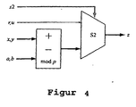
- encoders KA and decoder DB are in one Block diagram shown. Again, the bold apply drawn data flow paths for normal operation.
- the Reconstruction of the signal is correct if that Signal b is a copy of the signal a.
- Especially simple is the binary case where both functions be realized by the logical antivalence.
- both circuits with a selector S2 equipped for switching through the Shift register output or the constants u is provided during the first coupling (Stamping) is switched to the output z and must have a signal value that is safe State of the receiving circuit B establishes.
- the selector S2 is set by the signal s2.
- the illustrated in Fig. 1 detector FB in Reception circuit B consists of a comparator, the the signal z supplied by the decoder DB permanently with a reserved value f.
- This value either does not appear in the signal x to be transmitted or has the meaning that in the binary case a unauthorized signal transmission detected and the corresponding function, e.g. Lock, is triggered. Even if the signal to be transmitted does not have the value f contains, if the signals a and b (i.e., unauthorized coupling) the signal z sometime accept the value f and from the comparator be recognized.
- the likelihood of it growing with the length of the observation period; the on average required number of bars is linear of kp dependent.
- the further evaluation of the error signal and the output signal z is not the subject of Invention. It is possible, for example, a to connect the connected error register only if the error signal is longer than a certain one Time interval is applied or the clock signal with to evaluate any relative shifts in the Equalize edges of the signals a and b.
- a central Unprotected clock supply has the disadvantage that by illegally extending or shortening the clock period, the time to error detection extended or the necessary observation time for an unjustified imitation can be shortened.
- the value store of the signals comprises the values 0,1,2.
- the possible in a binary implementation of the circuit also signal value 3 could be for an additional backup, for.
- the table contains nine entries with the indices 0, 1, ... 8. It is therefore expected that the hash function does not exceed this range and if possible completes completely.
- a corresponding special solution is shown in the following Figure 5.
- the Shift register is connected to two outputs (at the cells 2 and 6) and tapped this pair as double digits Ternary number interpreted, with the higher-order part associated with cell 2. This is the value of Cell 2 multiplied by the number 3 and the value from cell 6 added.
- each possible ordered pair of values at cells 2 and 6 occur with equal frequency. This means that the address values calculated by the hash function are equally distributed.
- Phase 3 will be completed by Restarting the feedback network and the Commissioning of the encoder KA or the decoder KB.
- the diagram shown in Fig. 6 relates to Signal curve at the output of the feedback coupling network (1) as well as after the modification by values which the Column 0 of the memory has been taken a.
- the Recording begins after the end of phase 3 and includes 50 clock periods.
- FIG. 7 shows the same period of time at the output of the encoder KA visible signal y when a control pulse x the Amplitude I in the time interval of clock 10 to 25 acts. You realize that it's not just big trouble prepares a desired signal through replica but also without knowing the signal a from the signal y to reconstruct the input x.
- the clock signals in the two involved circuits, transmission circuit A and Reception circuit B to be generated separately and during phase 1 of the "coinage" one Initial synchronization by means of the signal r done.
- the further maintenance synchronization can then from the Signal y are derived. That can be with you happen known phase locked loop.
- the present Invention allows the use of any Synchronization method in which signal r never and signal y very rarely episodes of more than (k-1) contains identical values.
- the receiving circuit B is structurally designed so and with the aggregate to be controlled (e.g. Machine, control and the like.) To couple that Attempt to penetrate their circuit with high time and technical effort and the possible Damage or destruction of the unit connected is. This is necessary to include the injection a false signal z in the unit bypassing to prevent the invention. It may not be possible be, the concealed in receiving circuit B machine table and to read the state of the machine directly or the exit of the machine AB for a sufficiently long time observe. It may be from the reactions of the connected aggregates to the output of the Decoder DB closed, but because of Output b of the machine AB can not be predicted can, is the correct generation one of one unauthorized user desired signal y highest unlikely, unless he has sufficient Knowledge about the machine AA.
- the aggregate to be controlled e.g. Machine, control and the like.
- Transmission circuit A that they only very is difficult to access and for the purpose of exclusion from unauthorized manipulation of the control variable x must be with a corresponding sensor (e.g., emergency switch, card reader, Break detector, radio reception channel) inseparable be coupled.
- a corresponding sensor e.g., emergency switch, card reader, Break detector, radio reception channel
- control signal x is also routed to the automaton AA and in unit B the signal z is also routed to the automaton AB in comparison to the representation in FIG.
- the automaton AA shown in FIG. 9 (which is identical to the automaton AB) is widened compared to the illustration in FIG. 2 by the selector S3, the circuit G and a D flip-flop for processing the signal x and z, respectively.
Landscapes
- Engineering & Computer Science (AREA)
- Computer Security & Cryptography (AREA)
- Computer Networks & Wireless Communication (AREA)
- Signal Processing (AREA)
- Storage Device Security (AREA)
- Burglar Alarm Systems (AREA)
Description
Es zeigen:
- Fig. 1
- ein Blockschaltbild der Sendeschaltung A und der Empfangsschaltung B mit gemeinsamer Taktversorgung
- Fig.2
- die identischen Automaten AA, AB der Sendeschaltung A und der Empfangsschaltung B,
- Fig.3
- die Steuereinheit UB in Empfangsschaltung B, die mit Steuerschaltung UA in Sendeschaltung A identisch ist,
- Fig.4
- den Codierer KA in der Sendeschaltung A und Decodierer DB in der Empfangsschaltung B,
- Fig.5
- ein Signalflußplan der Automaten AA bzw. AB,
- Fig.6
- ein Diagramm des Signalverlaufes am Ausgang eines Automaten,
- Fig.7
- ein Diagramm des Signalverlaufes des Signals y.
- Fig.8
- ein Blockschaltbild der Sendeschaltung A und der Empfangsschaltung B mit Verzweigung des Signals x zum Automaten AA und des Signals z zum Automaten AB,
- Fig.9
- die identischen Automaten AA, AB der Sendeschaltung A und der Empfangsschaltung B mit Schaltungsteilen zur Verarbeitung des Signals x bzw. z
Diese besteht aus dem Automaten AB, dem Decodierer DB und dem Detektor FB.
| k | ℓ=2k-1 | m= (ℓ)/k | m/l %] | └log2m┘ |
| 17 | 131071 | 7710 | 5,88 | 12 |
| 19 | 524287 | 27594 | 5,26 | 14 |
| 23 | 8388607 | 356960 | 4,26 | 18 |
| 25 | 33554431 | 1296000 | 3,86 | 20 |
| 29 | 536870911 | 18407808 | 3,43 | 24 |
| 31 | 2147483647 | 69273666 | 3,23 | 26 |
| 35 | 34359738367 | 929275200 | 2,70 | 29 |
| 37 | 137438953471 | 3697909056 | 2,69 | 31 |
| 41 | 2199023255551 | 53630700752 | 2,44 | 35 |
| 43 | 8796093022207 | 204064589160 | 2,32 | 37 |
| 47 | 140737488355327 | 2992477516800 | 2,13 | 41 |
| 49 | 562949953421311 | 11389311767808 | 2,02 | 43 |
| 53 | 9007199254740991 | 169917983040000 | 1,89 | 47 |
| 55 | 36028797018963967 | 598690870272000 | 1,66 | 49 |

Phase 1 beginnt mit dem Schließen der Rückkopplung durch den Selektor S1 mittels des Signals s1 und dem sofort oder kurz darauf folgenden Wechseln des Schreibsignals w, wodurch aus dem Koeffizientenspeicher P ein Koeffizientensatz ausgewählt und in die Koeffizientenregister geladen wird. Gleichzeitig wird das Steuersignal s2 derart gestellt, daß am Ausgang der Sendeschaltung A und der Empfangsschaltung B das aus dem Schieberegister austretende Signal r bzw. die unschädliche Konstante u beobachtet werden können. Die Belegung des Signals s2 wird erst geändert, wenn die Phase 3 abgeschlossen wird und der Normalbetrieb beginnt. Die beiden Automaten AA und AB arbeiten nunmehr autonom mit zufällig gewählten Anfangsbedingungen und Koeffizienten. Nach Ablauf einer zufälligen Zeitspanne wird Phase 2 in der Baueinheit A erreicht. Die den nicht rückgekoppelten Eingang des Selektors S1 in der Empfangsschaltung B und der Sendeschaltung A beobachtende Erkennungsschaltung M kann nicht ansprechen, weil Signale aus linearen rückgekoppelten Schieberegistern, die zur Erkennung erforderlichen Eigenschaften nicht haben.
In Phase 2 wird der Takt t1 derart angehalten, daß das Schieberegister im Automaten AA "eingefroren" wird. Durch abermaliges Setzen des Schreibsignals w wird mittels der Hashfunktion der zum zufälligen Inhalt des Schieberegisters gehörende Koeffizientensatz aus dem Koeffizientenspeicher P geladen. Der Automat AB wird weiter durch t2 getaktet und befindet sich vorläufig weiter in Phase 1. Genau k Takte nach dem Übergang von Automat AA in Phase 2 versetzt die Erkennungsschaltung M den Automaten AB direkt in die Phase 3. Gleichzeitig passiert das auch im Automaten AA.
| d(i,j) | 0 | 1 | 2 | 3 | 4 | 5 | 6 | 7 | 8 |
| 0 | 0 | 0 | 0 | 0 | 0 | 2 | 0 | 0 | 1 |
| 1 | 0 | 0 | 2 | 0 | 0 | 0 | 1 | 1 | 1 |
| 2 | 2 | 0 | 1 | 0 | 1 | 0 | 1 | 1 | 1 |
| 3 | 0 | 2 | 0 | 2 | 0 | 2 | 2 | 0 | 1 |
| 4 | 0 | 2 | 2 | 2 | 1 | 2 | 2 | 0 | 1 |
| 5 | 0 | 2 | 1 | 2 | 1 | 0 | 2 | 2 | 1 |
| 6 | 1 | 1 | 0 | 1 | 0 | 1 | 2 | 0 | 1 |
| 7 | 0 | 1 | 2 | 1 | 1 | 2 | 1 | 2 | 1 |
| 8 | 0 | 1 | 1 | 1 | 1 | 1 | 1 | 2 | 1 |
| Stufe | 1 | 2 | 3 | 4 | 5 | 6 | 7 | 8 |
| Inhalt | 1 | 1 | 0 | 2 | 2 | 1 | 0 | 0 |
| Stufe | 1 | 2 | 3 | 4 | 5 | 6 | 7 | 8 |
| Inhalt | 0 | 1 | 1 | 0 | 2 | 2 | 1 | 0 |
In dem in Figur 8 dargestellten Blockschaltbild wird gegenüber der Darstellung in Figur 1 in Einheit A das Steuersignal x auch zum Automaten AA und in Einheit B das Signal z auch zum Automaten AB geführt. Der in Figur 9 dargestellte Automat AA (der zum Automaten AB identisch ist) ist gegenüber der Darstellung in Figur 2 um den Selektor S3, die Schaltung G und ein D-Flip-Flop zur Verarbeitung des Signals x bzw. z erweitert.
Claims (10)
- Verfahren zur Herstellung und Erkennung der Authentizität von Befehlssignalen, die, in einem Sender erzeugt, drahtgebunden oder drahtlos zu einer diese Signale verarbeitenden Empfangsschaltung, übertragen werden,
dadurch gekennzeichnet, dass bei erstmaliger Inbetriebnahme einer Sendeschaltung (A) diese mit einer gleichzeitig oder verzögert eingeschalteten Empfangsschaltung (B) gekoppelt wird, wobei eine Steuereinheit (UA) der Sendeschaltung (A) aus einem in einem Automaten (AA) der Sendeschaltung (A) gespeicherten, erst nach Ablauf einer Beobachtungs- und Auswertzeit reproduzierbaren Signal ein Koppelsignal a erzeugt, dessen Charakteristik mittels einer gleichgetakteten Steuereinheit (UB) der Empfangsschaltung (B) dort in einem Automaten (AB) einmalig, nicht löschbar und nicht wiederholbar gespeichert wird und die Sendeschaltung (A) und Empfangsschaltung (B) funktionell untrennbar zusammenschließt. - Verfahren nach Anspruch 1,
dadurch gekennzeichnet, dass zur pseudozufälligen Modifikation das Koppelsignal a durch eine Addition des aus dem aktuellen Zustand des Automaten (AA) der Sendeschaltung (A) abgeleiteten Wertes mit dem rückgekoppelten Wert aus einem jeweiligen Rückführungssignal gebildet wird. - Verfahren nach Anspruch 1,
dadurch gekennzeichnet, dass ein "prägendes" Koppelsignal a in drei Phasen erzeugt und verarbeitet wird, derart,
dass in Phase 1 ein aus einem Koeffizientenspeicher (P) ausgewählter Koeffizientensatz in Koeffizientenregister geladen und gleichzeitig die Belegung eines Steuersignals s bis zur Beendigung von Phase 3 unverändert bleibt,
daß in Phase 2 der Takt t1 angehalten, dadurch der in Phase 1 erreichte Zustand des Automaten (AA) der Sendeschaltung (A) "eingefroren" wird, während sich Automat (AB) in der Empfangsschaltung (B) noch in Phase 1 befindet, bis er mindestens k Takte nach Übergang des Automaten (AA) der Sendeschaltung (A) in Phase 2 von einer Erkennungsschaltung (M) der Steuereinheit (UB) der Empfangsschaltung (B) gleichzeitig mit Automat (AA) der Sendeschaltung (A) in Phase 3 versetzt wird,
dass in Phase 3 durch Umschaltung eines Selektors (S1) ein Signal r aus einer Schiebezelle (Rk) des Automaten (AA) der Sendeschaltung (A) sowohl in diese als auch die des Automaten (AB) der Empfangsschaltung (B) einspeist, so dass aufgrund des wieder im Automat (AA) der Sendeschaltung (A) anliegenden Taktsignals t1 nach Ablauf von mindestens k Takten die Zustände der beiden Automaten (AA) und (AB) identisch sind, wobei wiederum ein aus dem Koeffizientenspeicher (P) ausgewählter Koeffizientensatz in die Automaten (AA) und (AB) geladen wird. - Verfahren nach Anspruch 3,
dadurch gekennzeichnet, dass das "prägende" Koppelsignal a nur ein einziges Mal erzeugt und übertragen wird. - Anordnung mit einer Sendeschaltung und einer Empfangsschaltung zur Herstellung und Erkennung der Authentizität von Befehlssignalen, welche in der Sendeschaltung erzeugt und drahtgebunden oder drahtlos zu der diese Signale verarbeitenden Empfangsschaltung übertragen werden, wobei die Sendeschaltung und die Empfängerschaltung identisch ausgebildete, mit einem Taktsignal beaufschlagte Steuereinheiten, Automaten, einen Detektor, Kodierer und Dekodierer aufweisen, wobei der Detektor zur Erkennung nicht authentischer Befehlssignale und/oder Unterbrechung des Übertragungskanals und/oder der internen Stromversorgung dient und die Senderschaltung (A) und die Empfangsschaltung (B) bei erstmaliger Inbetriebnahme mittels eines Koppelsignals a koppelbar ausgebildet sind,
dadurch gekennzeichnet, dass die Steuereinheit (UA) der Sendeschaltung (A) so ausgelegt ist, dass sie aus einem in dem Automaten (AA) der Sendeschaltung (A) gespeicherten, erst nach Ablauf einer Beobachtungs- und Auswertzeit reproduzierbaren Signal ein Koppelsignal a erzeugt, dass die gleichgetaktete Steuereinheit (UB) der Empfangsschaltung (B) so ausgelegt ist, dass sie in dem Automaten (AB) der Empfangsschaltung (B) die Charakteristik des Koppelsignals a einmalig, nicht löschbar und nicht wiederholbar speichert und die Sendeschaltung (A) und Empfangsschaltung (B) funktionell untrennbar zusammenschließt, dass der Kodierer (KA) der Sendeschaltung (A) derart ausgelegt ist, dass er aus einem Eingangssignal x und dem Koppelsignal a am Ausgang des Automaten (AA) der Sendeschaltung (A) ein Ausgangssignal y=x+a erzeugt und dass der Dekodierer (DB) der Empfangsschaltung (B) so ausgelegt ist, dass er aus dem Signal y und einem zum Koppelsignal a identischen Signal b am Ausgang des Automaten (AB) der Empfangsschaltung (B) ein Endsignal z=y-a erzeugt. - Anordnung nach Anspruch 5,
gekennzeichnet durch,
Mittel, die das Eingangssignal x zum Automaten (AA) der Sendeschaltung (A) und das Endsignal z zum Automaten (AB) zur Empfangsschaltung (B) führen. - Anordnung nach Anspruch 5,
dadurch gekennzeichnet, dass für die Sendeschaltung (A) und die Empfangsschaltung (B) ein gemeinsamer Taktgenerator (C) angeordnet ist. - Anordnung nach Anspruch 7,
dadurch gekennzeichnet, dass der Taktgenerator (C) in der Sendeschaltung (A) angeordnet ist. - Anordnung nach Anspruch 5,
dadurch gekennzeichnet, dass sowohl die Sendeschaltung (A) als auch die Empfangsschaltung (B) jeweils mit Taktgeneratoren ausgerüstet sind, die durch das übertragene Signal y phasenrichtig synchronisiert sind. - Anordnung nach Anspruch 5,
dadurch gekennzeichnet, dass die Empfangsschaltung (B) ein Stellglied ist.
Applications Claiming Priority (2)
| Application Number | Priority Date | Filing Date | Title |
|---|---|---|---|
| DE19541116A DE19541116A1 (de) | 1995-10-26 | 1995-10-26 | Verfahren und Anordnung zur Herstellung und Erkennung der Authentizität von Befehlssignalen |
| DE19541116 | 1995-10-26 |
Publications (3)
| Publication Number | Publication Date |
|---|---|
| EP0771094A2 EP0771094A2 (de) | 1997-05-02 |
| EP0771094A3 EP0771094A3 (de) | 2000-02-23 |
| EP0771094B1 true EP0771094B1 (de) | 2005-08-24 |
Family
ID=7776607
Family Applications (1)
| Application Number | Title | Priority Date | Filing Date |
|---|---|---|---|
| EP96250243A Expired - Lifetime EP0771094B1 (de) | 1995-10-26 | 1996-10-24 | Verfahren und Anordnung zur Herstellung und Erkennung der Authentizität von Befehlssignalen |
Country Status (2)
| Country | Link |
|---|---|
| EP (1) | EP0771094B1 (de) |
| DE (2) | DE19541116A1 (de) |
Family Cites Families (12)
| Publication number | Priority date | Publication date | Assignee | Title |
|---|---|---|---|---|
| DE2322037A1 (de) * | 1973-05-02 | 1974-11-21 | Max Rhodius Weissenburger Meta | Berieselungs-rueckkuehlanlage |
| FR2568040B1 (fr) * | 1984-07-18 | 1989-12-01 | Lewiner Jacques | Installation de commande et de controle des differentes serrures codees d'un ensemble |
| WO1989002507A1 (en) * | 1987-09-18 | 1989-03-23 | Innovation Marketing Limited | Security lock arrangement |
| DE3905651A1 (de) * | 1989-02-24 | 1990-08-30 | Daimler Benz Ag | Verfahren zur sicherung von codeworten eines fernwirksystems und fernwirksystem mit durch codeworte uebertragbarem code |
| JP3145112B2 (ja) * | 1990-04-06 | 2001-03-12 | シーメンス アクチエンゲゼルシヤフト | 車両用リモートロック装置 |
| US5144667A (en) * | 1990-12-20 | 1992-09-01 | Delco Electronics Corporation | Method of secure remote access |
| DE4240458C1 (de) * | 1992-12-02 | 1993-12-23 | Grundig Emv | Vorrichtung zum Schutz von Kraftfahrzeugen und darin befindlichen elektronischen Geräten vor Diebstahl |
| DE9301684U1 (de) * | 1993-02-06 | 1993-07-08 | Haggert, Horst-Jürgen, 6084 Gernsheim | KFZ-Batterie-Kompakt-Abdeckhaube |
| DE4318596A1 (de) * | 1993-06-04 | 1994-12-08 | Kizler Peter Dr | Diebstahlsicherung für Kraftfahrzeuge |
| DE4321417A1 (de) * | 1993-06-26 | 1995-01-05 | Deutsche Aerospace | Ortungsverfahren zum Wiederauffinden gestohlener oder nicht auffindbarer Fahrzeuge und Anordnung zum Durchführen des Verfahrens |
| DE4328781A1 (de) * | 1993-08-26 | 1995-03-02 | Siemens Ag | Anordnung zur Überprüfung der Zugangsberechtigung einer Informationssenke zu einer Informationsquelle |
| DE4342641A1 (de) * | 1993-12-14 | 1995-06-22 | Siemens Ag | Verfahren zur Authentifikation zwischen einem mobilen Datenträger und einer stationären Datenstation |
-
1995
- 1995-10-26 DE DE19541116A patent/DE19541116A1/de not_active Withdrawn
-
1996
- 1996-10-24 DE DE59611261T patent/DE59611261D1/de not_active Expired - Fee Related
- 1996-10-24 EP EP96250243A patent/EP0771094B1/de not_active Expired - Lifetime
Also Published As
| Publication number | Publication date |
|---|---|
| DE19541116A1 (de) | 1997-04-30 |
| DE59611261D1 (de) | 2005-09-29 |
| EP0771094A2 (de) | 1997-05-02 |
| EP0771094A3 (de) | 2000-02-23 |
Similar Documents
| Publication | Publication Date | Title |
|---|---|---|
| DE4411450C1 (de) | Fahrzeugsicherungseinrichtung mit elektronischer Nutzungsberechtigungscodierung | |
| DE4411451C1 (de) | Fahrzeugsicherungseinrichtung mit elektronischer Nutzungsberechtigungscodierung | |
| DE4418069C1 (de) | Sicherungseinrichtung mit elektronisch codierter Zugangsberechtigung für ein Fahrzeug | |
| DE4411449C1 (de) | Fahrzeugsicherungseinrichtung mit elektronischer Nutzungsberechtigungscodierung | |
| EP0212046B1 (de) | System zum Ver- und/oder Entriegeln einer Sicherheitseinrichtung | |
| DE3905651C2 (de) | ||
| DE102011014688B3 (de) | Kraftwagen-Steuergerät mit kryptographischer Einrichtung | |
| EP0942856B1 (de) | Verfahren zur sicherung der datenübertragung | |
| DE3836026C2 (de) | ||
| EP0631408A2 (de) | Verfahren zur Authentifikation zwischen zwei elektronischen Einrichtungen | |
| EP0723896A2 (de) | Verfahren zur Diebstahlsicherung motorangetriebener Kraftfahrzeuge | |
| EP0937845B1 (de) | Freigabesystem für die Freigabe von Funktionen einer Einrichtung | |
| DE3641230C1 (de) | Verfahren und Schaltungsanordnung zur Diebstahlsicherung von Geraeten,insbesondere Autoradiogeraeten | |
| DE4433499C2 (de) | Elektronisches Diebstahlschutzsystem für ein Kraftfahrzeug | |
| EP0377128A1 (de) | Zündanlage für Kraftfahrzeuge | |
| DE19600556A1 (de) | Verfahren zum Betreiben eines Diebstahlschutzsystems und Diebstahlschutzsystem | |
| DE10015307B4 (de) | Verfahren und Vorrichtung zum Schutz eines Gerätes vor Diebstahl | |
| DE19960958B4 (de) | Vorrichtung zum Diebstahlschutz | |
| DE69421923T2 (de) | Antidiebstahlverfahren, und korrespondierende Schaltkreise und elektrische Systeme | |
| EP0830273B1 (de) | Wegfahrsperre | |
| DE10354517B4 (de) | Verfahren zum Betreiben eines Sicherheits-Schließsystems | |
| DE19960959A1 (de) | Vorrichtung zum manipulationssicheren Datenaustausch in einem Kraftfahrzeug | |
| DE19541116A1 (de) | Verfahren und Anordnung zur Herstellung und Erkennung der Authentizität von Befehlssignalen | |
| DE102007005068B3 (de) | Diebstahlsicherungssystem | |
| DE69524832T2 (de) | Fahrzeugdiebstahlsicherung |
Legal Events
| Date | Code | Title | Description |
|---|---|---|---|
| PUAI | Public reference made under article 153(3) epc to a published international application that has entered the european phase |
Free format text: ORIGINAL CODE: 0009012 |
|
| AK | Designated contracting states |
Kind code of ref document: A2 Designated state(s): DE ES FR GB IT SE |
|
| PUAL | Search report despatched |
Free format text: ORIGINAL CODE: 0009013 |
|
| AK | Designated contracting states |
Kind code of ref document: A3 Designated state(s): DE ES FR GB IT SE |
|
| RIC1 | Information provided on ipc code assigned before grant |
Free format text: 7H 04L 9/32 A, 7B 60R 25/00 B, 7E 05B 49/00 B |
|
| 17P | Request for examination filed |
Effective date: 20000823 |
|
| 17Q | First examination report despatched |
Effective date: 20020709 |
|
| RAP1 | Party data changed (applicant data changed or rights of an application transferred) |
Owner name: 4TECH GESELLSCHAFT FUER TECHNOLOGIE- UND KNOW-HOW- |
|
| GRAP | Despatch of communication of intention to grant a patent |
Free format text: ORIGINAL CODE: EPIDOSNIGR1 |
|
| GRAS | Grant fee paid |
Free format text: ORIGINAL CODE: EPIDOSNIGR3 |
|
| GRAA | (expected) grant |
Free format text: ORIGINAL CODE: 0009210 |
|
| AK | Designated contracting states |
Kind code of ref document: B1 Designated state(s): DE ES FR GB IT SE |
|
| PG25 | Lapsed in a contracting state [announced via postgrant information from national office to epo] |
Ref country code: IT Free format text: LAPSE BECAUSE OF FAILURE TO SUBMIT A TRANSLATION OF THE DESCRIPTION OR TO PAY THE FEE WITHIN THE PRESCRIBED TIME-LIMIT;WARNING: LAPSES OF ITALIAN PATENTS WITH EFFECTIVE DATE BEFORE 2007 MAY HAVE OCCURRED AT ANY TIME BEFORE 2007. THE CORRECT EFFECTIVE DATE MAY BE DIFFERENT FROM THE ONE RECORDED. Effective date: 20050824 Ref country code: ES Free format text: LAPSE BECAUSE OF FAILURE TO SUBMIT A TRANSLATION OF THE DESCRIPTION OR TO PAY THE FEE WITHIN THE PRESCRIBED TIME-LIMIT Effective date: 20050824 |
|
| REG | Reference to a national code |
Ref country code: GB Ref legal event code: FG4D Free format text: NOT ENGLISH |
|
| RIN2 | Information on inventor provided after grant (corrected) |
Inventor name: TARNICK, STEFFEN DR. Inventor name: WILHELMI, WOLFGANG, PROF. DR. |
|
| REF | Corresponds to: |
Ref document number: 59611261 Country of ref document: DE Date of ref document: 20050929 Kind code of ref document: P |
|
| PG25 | Lapsed in a contracting state [announced via postgrant information from national office to epo] |
Ref country code: SE Free format text: LAPSE BECAUSE OF FAILURE TO SUBMIT A TRANSLATION OF THE DESCRIPTION OR TO PAY THE FEE WITHIN THE PRESCRIBED TIME-LIMIT Effective date: 20051124 |
|
| GBT | Gb: translation of ep patent filed (gb section 77(6)(a)/1977) |
Effective date: 20051220 |
|
| PLBE | No opposition filed within time limit |
Free format text: ORIGINAL CODE: 0009261 |
|
| STAA | Information on the status of an ep patent application or granted ep patent |
Free format text: STATUS: NO OPPOSITION FILED WITHIN TIME LIMIT |
|
| 26N | No opposition filed |
Effective date: 20060526 |
|
| EN | Fr: translation not filed | ||
| PG25 | Lapsed in a contracting state [announced via postgrant information from national office to epo] |
Ref country code: FR Free format text: LAPSE BECAUSE OF FAILURE TO SUBMIT A TRANSLATION OF THE DESCRIPTION OR TO PAY THE FEE WITHIN THE PRESCRIBED TIME-LIMIT Effective date: 20061020 |
|
| PGFP | Annual fee paid to national office [announced via postgrant information from national office to epo] |
Ref country code: DE Payment date: 20070430 Year of fee payment: 11 |
|
| PGFP | Annual fee paid to national office [announced via postgrant information from national office to epo] |
Ref country code: GB Payment date: 20071011 Year of fee payment: 12 |
|
| PG25 | Lapsed in a contracting state [announced via postgrant information from national office to epo] |
Ref country code: DE Free format text: LAPSE BECAUSE OF NON-PAYMENT OF DUE FEES Effective date: 20080501 |
|
| PG25 | Lapsed in a contracting state [announced via postgrant information from national office to epo] |
Ref country code: FR Free format text: LAPSE BECAUSE OF FAILURE TO SUBMIT A TRANSLATION OF THE DESCRIPTION OR TO PAY THE FEE WITHIN THE PRESCRIBED TIME-LIMIT Effective date: 20051031 |
|
| PG25 | Lapsed in a contracting state [announced via postgrant information from national office to epo] |
Ref country code: FR Free format text: LAPSE BECAUSE OF FAILURE TO SUBMIT A TRANSLATION OF THE DESCRIPTION OR TO PAY THE FEE WITHIN THE PRESCRIBED TIME-LIMIT Effective date: 20050824 |
|
| GBPC | Gb: european patent ceased through non-payment of renewal fee |
Effective date: 20081024 |
|
| PG25 | Lapsed in a contracting state [announced via postgrant information from national office to epo] |
Ref country code: GB Free format text: LAPSE BECAUSE OF NON-PAYMENT OF DUE FEES Effective date: 20081024 |