EP0771010A2 - Câble amélioré de soudage à résistance primaire et ensemble - Google Patents
Câble amélioré de soudage à résistance primaire et ensemble Download PDFInfo
- Publication number
- EP0771010A2 EP0771010A2 EP96117099A EP96117099A EP0771010A2 EP 0771010 A2 EP0771010 A2 EP 0771010A2 EP 96117099 A EP96117099 A EP 96117099A EP 96117099 A EP96117099 A EP 96117099A EP 0771010 A2 EP0771010 A2 EP 0771010A2
- Authority
- EP
- European Patent Office
- Prior art keywords
- cable
- strain relief
- disposed
- resistance welding
- jacket
- Prior art date
- Legal status (The legal status is an assumption and is not a legal conclusion. Google has not performed a legal analysis and makes no representation as to the accuracy of the status listed.)
- Withdrawn
Links
Images


Classifications
-
- H—ELECTRICITY
- H01—ELECTRIC ELEMENTS
- H01B—CABLES; CONDUCTORS; INSULATORS; SELECTION OF MATERIALS FOR THEIR CONDUCTIVE, INSULATING OR DIELECTRIC PROPERTIES
- H01B7/00—Insulated conductors or cables characterised by their form
- H01B7/17—Protection against damage caused by external factors, e.g. sheaths or armouring
- H01B7/18—Protection against damage caused by wear, mechanical force or pressure; Sheaths; Armouring
- H01B7/24—Devices affording localised protection against mechanical force or pressure
-
- H—ELECTRICITY
- H01—ELECTRIC ELEMENTS
- H01B—CABLES; CONDUCTORS; INSULATORS; SELECTION OF MATERIALS FOR THEIR CONDUCTIVE, INSULATING OR DIELECTRIC PROPERTIES
- H01B7/00—Insulated conductors or cables characterised by their form
- H01B7/04—Flexible cables, conductors, or cords, e.g. trailing cables
- H01B7/041—Flexible cables, conductors, or cords, e.g. trailing cables attached to mobile objects, e.g. portable tools, elevators, mining equipment, hoisting cables
Definitions
- the present invention relates to an improved primary resistance welding cable assembly for robotic resistance welding and assembly equipment, or other suitable mechanically automated manufacturing equipment.
- electrical current e.g. 480 volts (V) and 110 amps (A)
- V voltage
- A higher amperage
- This current then passes through welding tips, and through resistive heat and pressure at the faying surface between two pieces of metal, a weld joint is formed.
- the high amperage current causes fusion of parts to be welded at the joint.
- a flexible primary electrical cable formed of two or more stranded conductors is typically connected between a power source and a transformer/welding gun.
- the welding gun includes welding tips which may be closed on opposite sides of the joint to be welded.
- the operation of the welding gun results in a continuous movement and flexing of the primary welding cable. Over time, this flexing causes the copper conductors within the cable to work harden which results in the breakage of the fine strands of the conductors. This results in the copper conductors within the primary welding cable to gradually increase in resistance over a period of time. As the resistance increases, the amount of heat generated in the cable increases, and the amount of current available for the welding tips of the welding gun reduces significantly. A drop in current eventually will produce an inferior weld. Also, increased heat generated at the conductors accelerates work hardening of the copper which leads to embrittlement and premature breakage.
- manufacturers replace welding cables at predetermined time intervals.
- the general practice is to shut down the welding line, disconnect the cable, and test the resistance of the cable. If the cable is satisfactory based on the resistivity limits defined by the manufacturer, the cable is reconnected and used until the next test period. If the resistance of the cable is found to be more than the predetermined percentage higher than the original cable resistance measured, the cable is replaced.
- the increase in cable resistance is dependent upon a number of factors, including temperature, the amount of flexing the cable has encountered, and the amount of use placed on the cable in the welding operation. Because of this, it is not possible to predict exactly when a cable is due for replacement.
- Conventional resistance welding cables include a termination which incorporates a stainless steel "Cord Grip” which is used to limit the twist or bend angle at the connector termination.
- Conventional resistance welding cables suffer from shortcomings which detract from their usefulness.
- the "Cord Grip" type strain relief and termination does not effectively reduce torsional strain, or fully protect the cable termination from failure due to the abrasion of the metal grip on the cable insulation which is inherent in the design.
- a resistance welding cable which comprises a plurality of electrical conductors, an insulation material which is disposed about each electrical conductor, and a jacket material which is disposed about the insulated conductors.
- the jacket material defines a predetermined diameter for the resistance welding cable.
- At least one connector or termination interface may be electrically terminated to at least a first end of the resistance welding cable.
- At least one strain relief may be made integral with the jacket material and the connector or termination interface.
- the at least one strain relief has at least a first frusto-conically shaped first portion defined by opposed first and second ends. The first end is defined by a diameter which is substantially equal to the diameter of the cable jacket.
- the second end is defined by a diameter which is greater than the diameter of the first end.
- the at least one strain relief provides a smooth continuous transition from the second end of the strain relief to the cable jacket.
- a wrapping of porous polytetrafluoroethylene may be disposed about each electrical conductor, wherein the insulation material is disposed about said wrapping of each electrical conductor.
- a wrapping of porous polytetrafluoroethylene may be disposed about the insulation material of each electrical conductor.
- a wrapping of porous polytetrafluoroethylene may be disposed about the plurality of electrical conductors to form a bundle of electrical conductors, wherein the jacket material is formed about said wrapping.
- the durometer hardness of the strain relief may be substantially equal to the durometer hardness of the cable jacket.
- the strain relief may additionally include a second portion which is molded with the first portion to form a unitary strain relief; the second portion encapsulating a predetermined portion of the at least one connector.
- the strain relief may be comprised of a two-part, castable polyurethane which chemically bonds to the cable jacket.
- the resistance welding apparatus comprises a robotic assembly 12, a trans-gun unit 14, a junction box 16, an improved resistance welding cable 18, made in accordance with the teachings of the present invention, and a power source (not shown).
- the trans-gun unit 14 includes a pair of welding tips 20 which may be closed on opposite sides of a joint to be welded (not shown).
- the trans-gun unit 14 is a combination of a transformer and a resistance weld gun.
- the resistance weld gun uses high current and pressure to produce a weld. Heat for the weld is generated by the resistance of the two pieces of metal being welded. Electrical power is provided to the trans-gun unit 14 through the resistance welding cable 18, which is electrically connected with the junction box 16, which may be located on an arm or hip of the robot.
- the transformer of the trans-gun unit 14 takes primary power at high voltage and transforms it into secondary power at high current. Typically, primary voltage may come in at 480 volts, which is transformed into secondary current, which may be as high as 13,000 to 15,000 amps, depending on the size of the trans-gun unit.
- the gun of the trans-gun unit 14 may typically have a kilo volt-amps (KVA) rating of between 45-150 KVA.
- KVA kilo volt-amps
- the primary resistance welding cable 18 of the present invention is not limited to the use illustrated herein. Instead, the primary resistance welding cable 18 may be used in any resistance welding operation, including but not limited to other robotic resistance welding operations or manual mechanical primary resistance welding operations.
- the conventional resistance welding cable includes a cable 25, a connector 24 and a strain relief 26.
- the strain relief 26 is typically referred to in the art as a "Cord Grip" type strain relief which comprises a stiff steel braid.
- the strain relief 26 does not adhere to a jacket of the cable 25 which causes significant abrasion of the cable 25 which results in an early failure of the cable.
- the strain relief 26 does not effectively reduce torsional strain upon the cable 22, which also may cause premature failure of the cable.
- the conventional resistance welding cable 22 does not provide a smooth transition from the strain relief 26 to the cable 25 which creates a pinch point on the cable jacket.
- the stiffness of the steel braid of the "Cord Grip" type strain relief does not allow bending flex near the connector. In minor bending, the cable 25 only flexes at the end of the braid.
- the resistance welding cable 18 of the present invention is best understood by reference to Figures 1-4.
- the resistance welding cable 18 includes a plurality of electrical conductors 30, at least one strain relief 32, and may include at least one electrical connector or anchoring device 34.
- the anchoring device may include, but is not limited to, threaded type inserts, or other suitable mechanical termination members.
- the plurality of electrical conductors 30 may be defined by 2/0 to 10 AWG (American Wire Gauge) bare copper.
- a tape 36 of porous polytetrafluoroethylene may be helically wrapped around each electrical conductor 30.
- the tape 36 may have a total wrap thickness of about 0.0045 thickness inches.
- a primary insulation 38 which may comprise polyurethane.
- the primary insulation may be applied in any suitable fashion, such as but not limited to extruding the material or polyurethane over each wrapped electrical conductor 30.
- An overall voltage rating of from about 300V to 2000V, and an overall temperature rating of from about 90°C to 105°C can be obtained by varying the wall thickness and formulations of insulation materials of the primary insulation.
- the primary insulation may have a thickness ranging from, but not limited to 0.030 to 0.110 inches.
- a tape 40 of porous polytetrafluoroethylene may be helically wrapped around each insulated electrical conductor 30. The tape 40 may have a total wrap thickness of about 0.0045 inches.
- the electrical conductors 30 are cabled, at which time a filler material 42 such as but not limited to, nylon, cotton, polyester rope or strands, or a wrapped, extruded polyurethane or other suitable cylindrical material, may be arranged in an intermingled fashion with the prepared electrical conductors 30.
- a binder tape 44 of porous polytetrafluoroethylene.
- the tape 44 may have a total wrap thickness of about 0.0045 inches.
- an overall cable jacket 46 which may comprise polyurethane of the same type used for the primary insulation 38.
- the cable jacket 46 may be applied in any suitable fashion, such as but not limited to extruding the polyurethane over the binder tape 44.
- the total wrap thickness of the cable jacket 46 may range from about 0.0045 inches to about 0.120 inches.
- porous polytetrafluoroethylene shall mean a membrane which may be prepared by any number of known processes, for example, by stretching or drawing processes, by papermaking processes, by processes in which filler materials are incorporated with the PTFE resin and which are subsequently removed to leave a porous structure, or by powder sintering processes.
- the porous polytetrafluoroethylene film is porous expanded polytetrafluoroethylene film having a microstructure of interconnected nodes and fibrils, as described in U.S. Patent Nos. 3,953,566 and 4,187,390, which are incorporated herein by reference, and which fully describe the preferred material and processes for making them.
- the porous polytetrafluoroethylene membrane may have a pore volume in a range from about 20 to about 98 percent.
- the above described design of the resistance welding cable 18 provides electrical conductors 30 that are isolated from the primary insulation 38. Also, the primary insulation 38 is isolated from the overall cable jacket 46. Such a design provides a construction in which the insulated electrical conductors 30 are constrained within a cable jacket 46, yet are moveable independent of each other and the cable jacket 46 when the cable experiences a bending flex. Accordingly, by reducing friction at the interfaces of the cable jacket 46 and the primary insulation 38, and the interfaces of the primary insulations 38 and the electrical conductors 30, stresses on the electrical conductors 30, can be reduced which causes flex life of the cable 18 to be increased.
- the strain relief 32 incorporates a two part polyurethane cast mold that is mechanically and chemically bonded to the cable jacket 46.
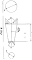
- the strain relief 32 is a frusto-conically shaped part that is molded directly to the cable assembly.
- frusto-conically means a part of a solid cone between two parallel planes cutting the solid cone, especially the section between the base and a plane parallel to the base of the cone.
- the shape of the strain relief 32 is important in that as the cross section of the strain relief increases, the moment of inertia increases. Since the maximum normal stresses are inversely proportional to the moment of inertia, the maximum normal stresses decrease as the moment of inertia increases. Therefore, as the bending moment increases along the cable 18 to the connector 34, the diameter of the strain relief increases along the cable to the connector 34, increasing the moment of inertia, resulting in the decreasing of the maximum normal stresses in the cable 18 and connector 34.
- the strain relief 32 may be molded or formed by any suitable material which may be made integral with, or may be affixed to, the cable jacket 46.
- the strain relief is molded from a two-part castable polyurethane to form a strain relief which bonds to the cable jacket 46. Because the strain relief 32 is made integral with the cable jacket 46, abrasion of the cable 18 is eliminated. Also, the strain relief 32 provides a smooth continuous transition from the strain relief to the cable 18, which eliminates pinch points. More particularly, and as best seen by reference to Figure 1, the strain relief is defined by a first portion 50 having a first end 52 and a second end 54. The first end 52 is defined by a diameter which is substantially equal to the diameter of the cable jacket 46.
- the second end 54 is defined by a diameter which is greater than the diameter of the first end 52.
- the first portion 50 of the strain relief 32 provides a smooth, continuous transition from the strain relief 32 to the cable 18, at the first end 52.
- the strain relief 32 also includes a second portion 56 which is molded with the first portion 50 to form the unitary strain relief 32.
- the second portion 56 of the strain relief 32 encapsulates a portion of the connector or anchoring device 34 thereby providing strain relief at the interface of the connector 34 and the cable 18.
- the durometer hardness of the strain relief 32 is substantially equal to the durometer hardness of the cable jacket 46 to permit bending flex near the connector 34.
- the strain relief 32 may be made in accordance with the teachings of U.S. Patent 4,814,412 which is incorporated herein by reference. In a preferred embodiment of the present invention, the strain relief 32 is formed in accordance with the following example, which is provided for purposes of illustration only, and is in no way intended to limit the teachings of the present invention.
- Component I consists of 100 parts of a mixture of aromatic polyisocyanates derived from methylene diphenyl diisocyanate having an isocyanate functionality of 2.2 and a free isocyanate content of 27.3%.
- Component P was prepared by mixing 88.3 parts of an ethylene oxide capped trio with a molecular weight of 4,500; 6.1 parts of 1,4 butanediol; 4.7 parts of an inorganic desiccant; 0.9 parts of carbon black powder; and 0.00005 parts of an organic tin catalyst, and then degassing the mixture under ambient conditions at 31.6 in. water for 1 hour.
- Components I and P were mixed at a 0.306:1 weight ratio for about two minutes in a desiccator.
- the mixture was de-gassed under vacuum for about 4-5 minutes, while the mixture was agitated.
- the mixture was removed from vacuum and gently shaken to remove any excess air bubbles. Thereafter, the mixture was poured into a mold.
- the mold was pretreated by coating the mold with a dry film mold release spray. Necessary inserts were added to the mold. The mold was heated to about 80°C. The interconnected cable 18, with connector 32, was then positioned within the mold.
- the mixture was allowed to cure in the heated mold at 80°C, for about 40 minutes.
- the gel time of the mixture was about 20 minutes.
- the reaction mixture had a ratio of molar equivalents of isocyanate to hydroxyl of 1.2.
- the polyurethane When cured, the polyurethane was an opaque black solid with a Shore A hardness of 60.
Applications Claiming Priority (2)
| Application Number | Priority Date | Filing Date | Title |
|---|---|---|---|
| US54822195A | 1995-10-25 | 1995-10-25 | |
| US548221 | 1995-10-25 |
Publications (2)
| Publication Number | Publication Date |
|---|---|
| EP0771010A2 true EP0771010A2 (fr) | 1997-05-02 |
| EP0771010A3 EP0771010A3 (fr) | 1998-06-10 |
Family
ID=24187896
Family Applications (1)
| Application Number | Title | Priority Date | Filing Date |
|---|---|---|---|
| EP96117099A Withdrawn EP0771010A3 (fr) | 1995-10-25 | 1996-10-24 | Câble amélioré de soudage à résistance primaire et ensemble |
Country Status (2)
| Country | Link |
|---|---|
| EP (1) | EP0771010A3 (fr) |
| JP (1) | JPH09191546A (fr) |
Cited By (2)
| Publication number | Priority date | Publication date | Assignee | Title |
|---|---|---|---|---|
| CN102685632A (zh) * | 2011-03-15 | 2012-09-19 | 美律电子(深圳)有限公司 | 无断差设计的耳机结构及其制造方法 |
| EP3226254A1 (fr) * | 2016-03-31 | 2017-10-04 | Omron Corporation | Câble en résine fluorée et dispositif électronique |
Citations (1)
| Publication number | Priority date | Publication date | Assignee | Title |
|---|---|---|---|---|
| US4814412A (en) | 1987-12-17 | 1989-03-21 | W. L. Gore & Associates, Inc. | Two component polyurethane system for casting expanded polytetrafluoroethylene |
Family Cites Families (2)
| Publication number | Priority date | Publication date | Assignee | Title |
|---|---|---|---|---|
| FR1231855A (fr) * | 1959-04-17 | 1960-10-04 | Perfectionnement apporté aux câbles électriques à conducteurs multiples et ses applications | |
| DE7146711U (de) * | 1971-12-11 | 1972-03-16 | Goldschmidt Th Ag | Kabel mit in Form eines Kabelbaumes freigelegten Kabelenden |
-
1996
- 1996-10-24 EP EP96117099A patent/EP0771010A3/fr not_active Withdrawn
- 1996-10-24 JP JP28240196A patent/JPH09191546A/ja active Pending
Patent Citations (1)
| Publication number | Priority date | Publication date | Assignee | Title |
|---|---|---|---|---|
| US4814412A (en) | 1987-12-17 | 1989-03-21 | W. L. Gore & Associates, Inc. | Two component polyurethane system for casting expanded polytetrafluoroethylene |
Cited By (3)
| Publication number | Priority date | Publication date | Assignee | Title |
|---|---|---|---|---|
| CN102685632A (zh) * | 2011-03-15 | 2012-09-19 | 美律电子(深圳)有限公司 | 无断差设计的耳机结构及其制造方法 |
| EP3226254A1 (fr) * | 2016-03-31 | 2017-10-04 | Omron Corporation | Câble en résine fluorée et dispositif électronique |
| US20170290180A1 (en) * | 2016-03-31 | 2017-10-05 | Omron Corporation | Fluororesin cable and electronic device |
Also Published As
| Publication number | Publication date |
|---|---|
| JPH09191546A (ja) | 1997-07-22 |
| EP0771010A3 (fr) | 1998-06-10 |
Similar Documents
| Publication | Publication Date | Title |
|---|---|---|
| EP2192601B1 (fr) | Faisceau de câbles et son procédé de fabrication | |
| JPH0475604B2 (fr) | ||
| WO2006008982A1 (fr) | Cordon électrique pour automobile | |
| CN101313372A (zh) | 汽车电线 | |
| US7696430B2 (en) | Metallic conductor and process of manufacturing same | |
| US9340924B2 (en) | Cable with electrical conductor included therein | |
| US20070017691A1 (en) | Covered wire and automobile-use wire harness | |
| EP3576104A1 (fr) | Câble d'isolation | |
| EP0771010A2 (fr) | Câble amélioré de soudage à résistance primaire et ensemble | |
| JP3454981B2 (ja) | ロボット用電線及びそれを用いたロボット用ケ−ブル | |
| JPH03207210A (ja) | 電気ケーブル継手用の格納可能な被覆要素 | |
| US2787653A (en) | Electric cables | |
| DE3144743A1 (de) | Elektrische, flexible leitung mit besonderer widerstandsfaehigkeit gegen torsionsbeanspruchung | |
| US2882333A (en) | Electric cable joints | |
| US5089666A (en) | Cable and method of manufacturing thereof | |
| Chu | A method to characterize the mechanical properties of undersea cables | |
| JPH0750567B2 (ja) | 機器配線用導体 | |
| US11699538B1 (en) | High-voltage electrical cable with mixed conductors | |
| JPH0743866Y2 (ja) | プローブケーブル | |
| EP3339231A1 (fr) | Connecteur pour câble de levage d'un appareil de levage | |
| JP2984879B2 (ja) | 高強度低伸度繊維を用いた複合ケーブルの端末定着部形成方法 | |
| JP2006032076A (ja) | 自動車用電線 | |
| CA1269424A (fr) | Conducteur sous isolant pour faisceau de cablage | |
| JP2024503163A (ja) | 引張歪みシースを備えている架空電気ケーブルの終端配列 | |
| JP2023152377A (ja) | 圧着構造の製造方法 |
Legal Events
| Date | Code | Title | Description |
|---|---|---|---|
| PUAI | Public reference made under article 153(3) epc to a published international application that has entered the european phase |
Free format text: ORIGINAL CODE: 0009012 |
|
| AK | Designated contracting states |
Kind code of ref document: A2 Designated state(s): DE ES FR GB IT NL SE |
|
| PUAL | Search report despatched |
Free format text: ORIGINAL CODE: 0009013 |
|
| AK | Designated contracting states |
Kind code of ref document: A3 Designated state(s): DE ES FR GB IT NL SE |
|
| STAA | Information on the status of an ep patent application or granted ep patent |
Free format text: STATUS: THE APPLICATION IS DEEMED TO BE WITHDRAWN |
|
| 18D | Application deemed to be withdrawn |
Effective date: 19981211 |