EP0770832B1 - Modular grid - Google Patents
Modular grid Download PDFInfo
- Publication number
- EP0770832B1 EP0770832B1 EP19960402260 EP96402260A EP0770832B1 EP 0770832 B1 EP0770832 B1 EP 0770832B1 EP 19960402260 EP19960402260 EP 19960402260 EP 96402260 A EP96402260 A EP 96402260A EP 0770832 B1 EP0770832 B1 EP 0770832B1
- Authority
- EP
- European Patent Office
- Prior art keywords
- blades
- grid
- support
- blade
- receiving
- Prior art date
- Legal status (The legal status is an assumption and is not a legal conclusion. Google has not performed a legal analysis and makes no representation as to the accuracy of the status listed.)
- Expired - Lifetime
Links
Images


Classifications
-
- F—MECHANICAL ENGINEERING; LIGHTING; HEATING; WEAPONS; BLASTING
- F24—HEATING; RANGES; VENTILATING
- F24F—AIR-CONDITIONING; AIR-HUMIDIFICATION; VENTILATION; USE OF AIR CURRENTS FOR SCREENING
- F24F13/00—Details common to, or for air-conditioning, air-humidification, ventilation or use of air currents for screening
- F24F13/08—Air-flow control members, e.g. louvres, grilles, flaps or guide plates
Definitions
- Patent FR-A-2,669,408 describes, for its part, a grid in wood made from blades kept spaced between them, two by two, by means of pairs of pieces bracing, the bracing parts being formed by a cylinder, each end of which is extended by a stud capable of being housed inside a recess in said blades. All the ventilation grilles described above have the same disadvantages, namely reduced modularity and inability to adapt to any format using identical standard items.
- the scales are therefore formed by a number of support modules inserted by sliding into each internal groove of the uprights. Depending on the size of the grid to be produced, a determined number of modules support must be introduced into the grooves of the uprights. It should also be noted that the skeleton positioning blades do not require successive stacking of the blades and scales. Indeed, the scales have receiving housings in which the blades are received by engagement.
- the blade support means comprise axis housings to receive axes on which swivel blades are mounted.
- the blades are reversible by rotation of a turn around along their longitudinal direction.
- the blades are not symmetrical about their axis longitudinal, they are however reversible. So with one and the same blade, it is possible to build two different grids by simply inverting the blades.
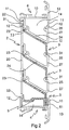
- FIG 2 we see a scale 2 fitted with 3 blades arranged in a lateral upright (not visible) at the ends of which are fixed two crosspieces horizontal 4. Although the side upright is not visible, we must imagine that the scale 2 equipped with these blades 3 is mounted captive on the upright 1 as shown in Figure 1. We see in Figure 2 that the scale 2 is locked in position by the horizontal crosspieces 4. As previously mentioned, the horizontal crosspieces 4 are formed with the same profile as the side uprights 2. Their structure is therefore completely identical and includes flaps 12 which partially close the inner groove 14.
- the grid illustrated in Figure 2 includes three blades 3, therefore, the ladder should have three pairs of reception housings 22, 25.
Description
La présente invention concerne une grille d'aération réalisée à partir d'éléments modulaires et destinée à être montée sur une ouverture formée dans un mur ou plus généralement une paroi. Ce genre de grille sert généralement de grille d'aération.The present invention relates to a ventilation grille made from modular elements and intended to be mounted on an opening formed in one or more walls usually a wall. This kind of grid is generally used ventilation grille.
De nombreuses grilles d'aération sont connues à ce jour. Les grilles d'aération les plus classiques sont constituées par des lames fixées à un cadre par agrafage au moyen de pattes que l'on replie. Il est également connu, par le brevet FR-A-2 328 164, une grille d'aération composée d'éléments modulaires fixés sur des montants, chaque élément modulaire se composant d'une lame solidarisée à une lame contiguë par un support de lame, chaque lame présentant, dans ce cas, sur sa face arrière, une gouttière à l'intérieur de laquelle le support de lame est susceptible de s'encliqueter de manière à rigidifier l'ensemble. Le brevet FR-A-2 669 408 décrit, quant à lui, une grille en bois réalisée à partir de lames maintenues espacées entre elles, deux à deux, au moyen de paires de pièces d'entretroisement, les pièces d'entretoisement étant constituées par un cylindre dont chaque extrémité est prolongée par un tenon susceptible de se loger à l'intérieur d'un évidement ménagé dans lesdites lames. Toutes les grilles d'aération décrites ci-dessus présentent les mêmes inconvénients, à savoir une modularité réduite et une incapacité d'adaptation à un format quelconque au moyen d'éléments identiques standards.Many ventilation grilles are known to date. The most classic ventilation grilles are made by blades fixed to a frame by stapling by means of legs that are folded. It is also known, by the patent FR-A-2 328 164, a ventilation grille composed modular elements fixed on uprights, each element modular consisting of a blade secured to a blade contiguous by a blade support, each blade having, in this case, on its rear side, a gutter to the interior of which the blade support is susceptible to snap so as to stiffen the assembly. The Patent FR-A-2,669,408 describes, for its part, a grid in wood made from blades kept spaced between them, two by two, by means of pairs of pieces bracing, the bracing parts being formed by a cylinder, each end of which is extended by a stud capable of being housed inside a recess in said blades. All the ventilation grilles described above have the same disadvantages, namely reduced modularity and inability to adapt to any format using identical standard items.
Le but de la présente invention est de pallier ces inconvénients en proposant une grille d'aération réalisée à partir d'éléments modulaires tous identiques indépendamment du format du châssis de la grille devant être fixé à l'ossature de bâtiment.The purpose of the present invention is to overcome these disadvantages by proposing a ventilation grille made at from modular elements all identical independently the format of the grid frame to be attached to the building framework.
Un autre but de la présente invention est de proposer une grille d'aération susceptible d'être montée de manière très rapide sans nécessiter l'utilisation d'outils spécifiques, toutes les liaisons des éléments constitutifs entre eux s'effectuant par encliquetage ou emboítement.Another object of the present invention is to provide a ventilation grille capable of being mounted so very fast without requiring the use of tools specific, all the connections of the constituent elements between them by snap-fitting or interlocking.
D'autre part, le document FR-A-2 713 319 divulgue une grille d'aération comprenant un cadre constitué de montants latéraux munis d'une rainure intérieure et reliés par des traverses, et des éléments modulaires composés de lames maintenues assemblées à claire-voie à l'intérieur dudit châssis. Le châssis est garni intérieurement par un empilement successif des lames maintenues à l'intérieur du cadre par des entretoises fixées par encliquetage aux extrémités de chaque lame. Les entretoises empilables sont maintenues entre le bord antérieur et le bord postérieur des rainures ménagées dans les montants latéraux du châssis. Dans cette grille d'aération, il est nécessaire d'empiler alternativement une lame et une entretoise, car les entretoises reposent sur les lames. Il n'est donc pas possible d'empiler successivement deux entretoises. En outre, il est possible d'extraire les entretoises de leurs rainures simplement par coulissement le long des lames. Etant donné que chaque entretoise n'est maintenue qu'entre les bords antérieur et postérieur des rainures formées dans le cadre, une fois l'entretoise extraite de ces rainures, il est possible de l'enlever de sorte que la grille peut être littéralement démontée. D'un point de vue sécuritaire, cette conception de grille d'aération n'offre pas toutes les garanties. Etant donné qu'il est extrêmement aisé de la démonter, et ceci sans utilisation d'aucun outil, n'importe quelle personne malveillante pourrait s'introduire dans le local équipé d'une telle grille. De plus, la modularité d'une telle grille se limite uniquement au nombre de lames qu'il faut disposer dans le cadre.On the other hand, document FR-A-2 713 319 discloses a ventilation grille comprising a frame made up of uprights side with an internal groove and connected by sleepers, and modular elements composed of blades kept assembled in skeleton inside said frame. The chassis is lined internally with a successive stacking of the blades held inside the frame by spacers fixed by snap to ends of each blade. The stackable spacers are maintained between the anterior edge and the posterior edge of the grooves in the side uprights of the chassis. In this ventilation grille, it is necessary to stack alternatively a blade and a spacer, because the spacers rest on the blades. It is therefore not it is possible to stack two spacers successively. In in addition, it is possible to extract the spacers from their grooves simply by sliding along the blades. Since each spacer is only held between the anterior and posterior edges of the grooves formed in the frame, once the spacer has been extracted from these grooves, it is possible to remove it so that the grid can be literally disassembled. From a security point of view, this ventilation grille design does not provide all guarantees. Since it is extremely easy to disassemble, and this without the use of any tool, which malicious person could break into the room equipped with such a grid. In addition, modularity of such a grid is limited only to the number of blades that you have to have in the frame.
Le document GB-2 178 159 décrit une grille de ventilation dans laquelle les extrémités de chaque lame sont emboítées dans des supports de lame individuels. Chaque support de lame est pourvu d'un seul logement de réception pour une extrémité de lame. Les supports de lame sont montés coulissants dans des rainures formées dans les montants du cadre de la grille. Les supports de lame sont ainsi empilés dans les rainures des montants. Les supports de lame sont réalisés par injection de matière plastique et non en métal.GB-2 178 159 describes a grid of ventilation in which the ends of each blade are nested in individual blade supports. Each blade holder has only one receiving housing for one blade end. Blade supports are mounted sliding in grooves formed in the uprights of the grid frame. The blade supports are thus stacked in the grooves of the uprights. The blade supports are made by injecting plastic and not metal.
D'autre part, on connaít du document FR-2 355 238 une grille dans laquelle les lames sont maintenues espacées par un fil à ressort qui forme les boucles dans lesquelles les lamelles sont introduites. Le fil à ressort est monté dans un étrier qui est ensuite vissé sur un bâti. Les extrémités des lames peuvent être reçues dans des boítiers de finition qui sont également vissés au bâti. Le fil à ressort n'est pas prévu pour être monté aux extrémités des lames auxquelles sont placés les boítiers. Cette grille présente donc les inconvénients suivants. D'une part, le fil à ressort n'offre aucune solidité, d'où il en résulte que la grille n'est pas inviolable, et d'autre part, la longueur définie de l'étrier élimine toute possibilité de modularité.On the other hand, we know from document FR-2 355 238 a grid in which the blades are kept spaced apart by a spring wire which forms the loops in which the coverslips are introduced. The spring wire is mounted in a stirrup which is then screwed onto a frame. The extremities blades can be received in finishing boxes which are also screwed to the frame. The spring wire is not not intended to be mounted at the ends of the blades to which the boxes are placed. This grid presents therefore the following disadvantages. On the one hand, the thread to spring offers no solidity, from which it follows that the grid is not inviolable, and on the other hand, the length defined bracket eliminates any possibility of modularity.
Le but de la présente invention est de pallier les inconvénients de l'art antérieur précité en définissant une grille qui offre une grande modularité aussi bien au niveau de sa taille que du type de lames utilisées, une grande facilité de montage, ainsi qu'une sécurité maximale, en ce sens qu'elle ne peut pas être démontée une fois installée, excepté par destruction.The purpose of the present invention is to overcome the disadvantages of the aforementioned prior art by defining a grid which offers great modularity both in terms of of its size than of the type of blades used, a large ease of assembly, as well as maximum safety, sense that it cannot be disassembled once installed, except by destruction.
Pour ce faire, la présente invention a pour objet une grille métallique comprenant :
- un cadre constitué de montants latéraux reliés par des traverses, au moins lesdits montants latéraux formant des rainures intérieures,
- des lames s'étendant entre les montants latéraux,
- des moyens de support de lame disposés dans les rainures intérieures pour maintenir les lames à claire-voie, les rainures intérieures étant pourvues de moyens de maintien pour maintenir les moyens de support de lame dans les rainures intérieures, lorsque le cadre est formé,
- a frame made up of lateral uprights connected by crosspieces, at least said lateral uprights forming internal grooves,
- blades extending between the lateral uprights,
- blade support means arranged in the interior grooves to hold the slatted blades, the interior grooves being provided with holding means for holding the blade support means in the interior grooves, when the frame is formed,
Une échelle est donc introduite par coulissement dans chaque rainure intérieure. Une fois les traverses assujetties aux montants, les échelles sont définitivement prisonnières des rainures.A ladder is therefore introduced by sliding into each interior groove. Once the sleepers subject to the amounts, the scales are definitively trapped in the grooves.
Selon une forme de réalisation pratique, chaque échelle comprend un ou plusieurs modules de support comprenant chacun une pluralité de logements de réception.According to a practical embodiment, each scale includes one or more support modules including each a plurality of reception housings.
Avantageusement, chaque module de support comprend trois logements de réception.Advantageously, each support module comprises three reception accommodation.
Les échelles sont donc formées par un certain nombre de modules de support introduits par coulissement dans chaque rainure intérieure des montants. En fonction de la taille de la grille à réaliser, un nombre déterminé de modules de support devra être introduit dans les rainures des montants. Il est également à noter que le positionnement à claire-voie des lames ne nécessite pas un empilement successif des lames et des échelles. En effet, les échelles sont dotées de logements de réception dans lesquels les lames sont reçues par engagement.The scales are therefore formed by a number of support modules inserted by sliding into each internal groove of the uprights. Depending on the size of the grid to be produced, a determined number of modules support must be introduced into the grooves of the uprights. It should also be noted that the skeleton positioning blades do not require successive stacking of the blades and scales. Indeed, the scales have receiving housings in which the blades are received by engagement.
Selon une forme de réalisation, les moyens de maintien comprennent des rabats qui referment partiellement les rainures intérieures pour former des rails de coulissement pour les moyens de support de lame. Les moyens de support de lame sont donc prisonniers des rainures intérieures par les rabats et il est donc impossible de les extraire une fois que le cadre est formé. Cela offre une sécurité accrue à la grille.According to one embodiment, the holding means include flaps that partially close the interior grooves to form sliding rails for the blade support means. Support means blade are therefore trapped in the interior grooves by the flaps and therefore cannot be removed once that the frame is formed. This provides added security to the wire rack.
Selon une autre caractéristique intéressante de l'invention, les moyens de support de lame comprennent des logements d'axe pour recevoir des axes sur lesquels des lames pivotantes sont montées. According to another interesting characteristic of the invention, the blade support means comprise axis housings to receive axes on which swivel blades are mounted.
Ainsi, en variante des lames fixes introduites par emboítement dans les logements de réception des échelles, il est possible de monter des lames pivotantes sur des axes de rotation montés dans les logements d'axe formés dans les moyens de support de lames. Ce genre de lames pivotantes agit tel un volet ou un clapet en fonction du courant d'air qui passe à travers la grille.Thus, as a variant, fixed blades introduced by nesting in the housing for receiving ladders, it is possible to mount swivel blades on axes of rotation mounted in the axis housings formed in the blade support means. This kind of swivel blades acts like a flap or a flap depending on the air flow which passes through the grid.
Selon encore une autre caractéristique de l'invention, les traverses forment également des rainures intérieures dotées de rabats, un élément de base étant monté coulissant dans la traverse inférieure, ledit élément de base comprenant un logement de réception pour recevoir l'arête inférieure d'une lame inférieure et des moyens d'appui pour recevoir l'arête inférieure d'une lame pivotante inférieure.According to yet another characteristic of the invention, the sleepers also form internal grooves provided with flaps, a basic element being slidably mounted in the lower cross member, said basic element including a receiving housing for receiving the edge lower of a lower blade and support means for receive the lower edge of a lower pivoting blade.
Cet élément de base est donc commun aux deux modes de mise en oeuvre de la grille, c'est-à-dire avec des lames fixes reçues par emboítement ou des lames pivotantes montées sur les axes de pivotement.This basic element is therefore common to the two modes of implementation of the grid, that is to say with blades fixed received by socket or mounted swivel blades on the pivot axes.
En outre, les lames sont réversibles par rotation d'un demi-tour le long de leur direction longitudinale. Bien que les lames ne soient pas symétriques par rapport à leur axe longitudinal, elles sont cependant réversibles. Ainsi, avec une seule et même lame, il est possible de construire deux grilles différentes en inversant simplement les lames.In addition, the blades are reversible by rotation of a turn around along their longitudinal direction. Although the blades are not symmetrical about their axis longitudinal, they are however reversible. So with one and the same blade, it is possible to build two different grids by simply inverting the blades.
L'invention sera maintenant plus amplement décrite en référence aux dessins joints donnant à titre d'exemple non limitatif, plusieurs formes de réalisation de la présente invention.The invention will now be described more fully in reference to the accompanying drawings giving by way of example no limiting, several embodiments of the present invention.
Sur les dessins :
- la figure 1 est une vue en perspective montrant un tronçon de montant d'un cadre d'une grille selon la présente invention,
- la figure 2 est une vue en coupe à travers un montant équipé d'une échelle et de lames selon une variante de réalisation de la présente invention,
- la figure 3 est une vue en section d'une échelle selon l'invention, et
- la figure 4 est une vue en coupe à travers un montant équipé d'une échelle et de lames pivotantes.
- FIG. 1 is a perspective view showing an upright section of a frame of a grid according to the present invention,
- FIG. 2 is a sectional view through an upright equipped with a ladder and blades according to an alternative embodiment of the present invention,
- FIG. 3 is a section view of a ladder according to the invention, and
- Figure 4 is a sectional view through an upright equipped with a ladder and pivoting blades.
Il sera maintenant fait référence aux figures 1 à 3 pour décrire de manière détaillée la conception d'une grille de la présente invention selon une première forme de réalisation.Reference will now be made to FIGS. 1 to 3 for describe in detail the design of a the present invention according to a first form of production.
La figure 4 illustre une seconde forme de réalisation d'une grille selon l'invention.Figure 4 illustrates a second embodiment of a grid according to the invention.
Sur la vue en perspective de la figure 1, on voit une
section de montant latéral désignée par la référence
numérique 1, faisant partie d'un cadre de préférence
rectangulaire ou carré constitué de deux montants latéraux
1, de préférence verticaux, et de deux traverses, de
préférence horizontales, désignées par la référence
numérique 4 sur les figures 2 et 4. Dans un but d'économie
et de simplicité, les montants latéraux et les traverses
horizontales 4 sont formées à partir d'un même profilé, de
préférence en aluminium. Comme visible sur les figures 1, 2
et 4, ce profilé comprend une âme 10 aux extrémités
longitudinales de laquelle s'étendent perpendiculairement
deux branches 11. Une des deux branches 11 se prolonge par
un listel 13 qui forme un encadrement pour la grille
destinée à masquer la maçonnerie de fixation de la grille.
La branche 11 prolongée par le listel 13 constitue donc le
côté extérieur visible de la grille. L'âme 10 et les deux
branches latérales 11 forment une rainure intérieure qui
s'étend sur tout le pourtour intérieur du cadre de la
grille. Selon l'invention, les branches latérales 11 sont
pourvues de rabats latéraux 12 qui referment partiellement
la rainure intérieure formée par l'âme 10 et les branches
latérales 11. Sur les figures, les rabats longitudinaux 12
s'étendent sur toute la longueur des branches latérales 11,
mais on peut également imaginer des rabats localisés à
distance les uns des autres. La fonction des rabats ou de
tous autres moyens similaires est de refermer partiellement
la rainure intérieure formée par l'âme 10 et les branches
latérales 11 de manière à réaliser un rail de maintien et de
coulissement.In the perspective view of Figure 1, we see a
lateral upright section designated by the reference
digital 1, preferably part of a frame
rectangular or square made up of two
Des moyens de support de lame désignés par la référence
numérique 2 pour disposer et maintenir les lames à claire-voie
se présentent sous la forme d'une échelle introduite
par coulissement dans la rainure intérieure du montant
latéral 1. L'échelle 2, plus visible sur la figure 3, est
donc prisonnière de la rainure intérieure du montant latéral
1. On peut aisément comprendre en se référant à la figure 1,
que l'échelle 2 peut librement coulisser dans la rainure
intérieure 14 du montant 1, sans qu'il soit possible de
l'extraire directement. Par conséquent, une fois le cadre
assemblé, l'échelle 2 est définitivement prisonnière de la
rainure intérieure 14 du montant 1. Un mode de montage d'une
grille selon l'invention sera donné ci-après.Blade support means designated by the reference
digital 2 to arrange and maintain the louvres
are in the form of an introduced scale
by sliding in the internal groove of the
L'échelle 2 comprend plusieurs logements de réception
pour recevoir les extrémités des lames 3 ou engagement
latéral par emboítement, le nombre de logements de réception
étant dépendant de la hauteur de la grille à réaliser. Les
échelles des figures 1 et 3, bien que présentant certaines
différences de conception, comprennent toutes deux une
barrette latérale longitudinale 20 à partir de laquelle
s'étendent à intervalles réguliers des branches de support
24. La barrette longitudinale 20 et les branches de support
24 forment au niveau de leur connexion une première série de
logements 22 qui sert à la réception de l'extrémité d'un
bord longitudinal d'une lame 3. Chaque branche de support 24
est également pourvu d'un logement d'axe 23 qui sert à la
réception d'un axe de réception pour des lames pivotantes
qui constitue un second mode de réalisation illustré sur la
figure 4. Chaque branche de support 24 comprend une partie
d'extrémité 27 qui s'étend parallèlement à la barrette
longitudinale 20. L'écartement entre les parties 27 et la
barrette longitudinale 20 correspond environ à la cote
intérieure de la rainure intérieure 14, correspondant à la
distance séparant les deux branches latérales 11. En outre,
l'épaisseur de l'échelle 2 correspond environ à la distance
séparant le rabat 12 de l'âme 10. Ainsi, l'échelle 2 peut
parfaitement coulisser sensiblement sans jeu dans la rainure
intérieure 14 du montant 1. Les parties d'extrémité 27
parallèles à la barrette longitudinale 20 se terminent par
des crochets 25 qui forment une seconde série de logements
de réception pour l'extrémité du bord inférieur 31 d'une
barrette 30. Les figures 1 et 3 représentent des échelles
avec des seconds logements de réception 25 de conception
différente. En effet, l'échelle de la figure 1 est pourvue
d'un crochet 25 sous la forme d'une partie coudée dans le
prolongement de la partie d'extrémité 27 parallèle à la
barrette 20. En revanche, l'échelle des figures 2, 3 et 4,
est pourvue d'un crochet 25 coopérant avec le rabat 12 pour
former ledit second logement de réception. Comme on peut le
voir sur la figure 2, une lame 3 est reçue par emboítement
dans l'échelle 2 avec ses extrémités, le bord supérieur 31
de la lame 3 étant reçu dans un logement de réception 22
formé à la jonction de la barrette 20 et d'une branche de
support 24, alors que l'extrémité inférieure 1 de la lame 3
est reçue dans le logement de réception 25 formé par la
branche de support 24 directement inférieure, dans le cas
d'une échelle réalisée selon les figures 2, 3 et 4. Dans le
cas d'une échelle réalisée selon la figure 1, les logements
de réception 22 et 25 pour une lame 3 sont formés par la
même branche de support 24. Hormis cette petite variante,
les formes de réalisation des figures 1 et 3 sont totalement
équivalentes.
En se référant à la figure 2, on voit une échelle 2
équipée de lames 3 disposées dans un montant latéral (non
visible) aux extrémités duquel sont fixées deux traverses
horizontales 4. Bien que le montant latéral ne soit pas
visible, on doit imaginer que l'échelle 2 équipée de ces
lames 3 est montée prisonnière du montant 1 comme représenté
sur la figure 1. On voit sur la figure 2 que l'échelle 2 est
bloquée en position par les traverses horizontales 4. Comme
précédemment mentionné, les traverses horizontales 4 sont
formées avec le même profilé que les montants latéraux 2.
Leur structure est donc totalement identique et comprend des
rabats 12 qui referment partiellement la rainure intérieure
14. La grille illustrée sur la figure 2 comprend trois lames
3, par conséquent, l'échelle doit comporter trois paires de
logements de réception 22, 25. Etant donné qu'avec le modèle
d'échelle des figures 2, 3 et 4, le second logement de
réception 25 est prévu en coopération avec le premier
logement de réception 22 formé par la branche de support 24
directement supérieure, l'échelle 2 ne comporte pas de
moyens de logements de réception 25 pour l'extrémité
inférieure 31 de la lame 3 située la plus en bas. Par
conséquent, selon l'invention, il est prévu un élément de
base 5 qui est introduit par coulissement dans la rainure
intérieure 14 de la traverse horizontale 4 située en bas.
Tout comme l'échelle 2, l'élément de base 5 présente des
cotes qui permettent son coulissement sensiblement sans jeu
dans la rainure intérieure 14. Pour la réception de
l'extrémité inférieure de la lame 3, l'élément de base 5
comporte un logement de réception 51 qui remplit le même
rôle qu'un logement de réception 25 de l'échelle. En outre,
l'élément de base 5 comprend une languette 53 dont la
fonction sera explicitée ci-après en référence à la figure
4.Referring to Figure 2, we see a
L'échelle de la grille représentée sur la figure 2
comprend trois branches de support 24 et est donc destinée
aux support de trois lames 3. Pour une grille de dimensions
supérieures, on prévoit une échelle comportant davantage de
branches de support 24. Ainsi, on peut imaginer de produire
les échelles avec un nombre défini de branches de support 24
qui seront ensuite coupées à la longueur voulue en fonction
du nombre de lames que comporte la grille à réaliser. Selon
un mode de réalisation pratique, une échelle peut être
divisée en un certain nombre de modules de support
comportant chacun une pluralité de branches de support 24 et
donc de logements de réception 22, 25. Par exemple, chaque
module de support peut comporter trois branches de support
24 comme représenté sur la figure 3. Donc par exemple, pour
la réalisation d'une grille comportant dix lames, il faudra
disposer dans chaque montant latéral trois modules de
support pour les neuf premières lames. Pour la dixième lame,
il faudra couper ou sectionner un élément de module de
support correspondant à une branche de support 24. Pour
faciliter cette section, la barrette longitudinale 20
comporte des lignes de rupture 28. Ainsi, avec des modules
de support destiné à trois lames, il est possible de
réaliser une échelle pour un nombre quelconque de lames.The scale of the grid shown in Figure 2
includes three
Les lames 3 peuvent présenter un profil en S comme sur
la figure 1, ou plutôt en Z comme sur la figure 2 avec un
angle arrondi 33 et un angle cassé 32. Bien que cette lame
ne soit pas totalement symétrique en raison de la différence
qui existe au niveau des angles 32 et 33, il est à noter
qu'elles sont parfaitement réversibles par rotation d'un
demi-tour le long de leur direction longitudinale. D'une
part, cela facilite grandement le montage, et d'autre part,
cela permet de varier l'esthétique de la grille en
retournant simplement les lames.The
Il sera maintenant décrit une opération complète de
montage d'une grille selon l'invention. On commence par
mesurer les dimensions de la baie que l'on veut équiper
d'une grille selon l'invention. On découpe ensuite le
profilé aux dimensions recueillies pour former les montants
latéraux et les traverses horizontales. Si cela est
nécessaire, on introduit dans la traverse horizontale
inférieure un élément de base 5 coupé à la longueur de la
traverse. Les deux montants latéraux 1 sont ensuite
assemblées sur la traverse inférieure à l'aide d'équerres
non représentées. Par le montage de deux montants latéraux,
l'élément de base 5 est définitivement prisonnier de la
rainure intérieure 14 de la traverse. Il n'est plus possible
d'extraire l'élément de base qui est maintenu dans la
rainure grâce au rabat 12.There will now be described a complete operation of
mounting of a grid according to the invention. We start with
measure the dimensions of the rack that we want to equip
of a grid according to the invention. We then cut the
profiled to the dimensions collected to form the uprights
lateral and horizontal crosspieces. If this is
necessary, we introduce in the horizontal crosspiece
lower a
Supposons que la grille adaptée à la baie en question
comporte sept lames. Sept lames sont donc découpées avec une
longueur sensiblement égale à la distance séparant les âmes
10 des deux montants latéraux 1. Une fois la découpe des
lames terminée, on commence par monter trois lames sur deux
modules de support. Les lames peuvent être emboítées par
leurs extrémités, mais de préférence, grâce à la
configuration des modules de support, les lames peuvent être
engagées latéralement dans leurs logements respectifs. En
effet, en se référant à la figure 2 par exemple, on voit que
la lame 3 peut être montée dans son logement en introduisant
la lame latéralement, c'est-à-dire en l'amenant par un bord
longitudinal dans le logement. Cette possibilité
d'engagement latéral des lames est très avantageux, car il
est souvent difficile d'emboíter l'extrémité d'une lame en
aluminium préalablement découpée dans un logement
correspondant en raison de la présence de barbes provenant
de la découpe des lames. En les engageant latéralement par
un bord non découpé, on évite ces difficultés. Une fois, les
trois lames ainsi montées sur leurs modules respectifs, on
introduit l'ensemble dans les rainures du cadre. Il est à
noter que l'ensemble présente déjà une bonne rigidité, ce
qui assure que les lames sont déjà parfaitement disposées à
l'équerre par rapport aux modules. Cela facilite grandement
l'introduction et le glissement des modules dans leurs
rainures respectives. Une fois cet ensemble de trois lames
et deux modules en place dans le cadre encore incomplet, on
recommence la même opération avec trois autres lames. On
introduit ensuite ce nouvel ensemble dans le cadre. Six
lames sont ainsi déjà en place.Suppose that the grid adapted to the bay in question
has seven blades. Seven blades are therefore cut with a
length substantially equal to the distance between the
Pour le montage de la septième lame, il suffit de couper
au niveau de la ligne de rupture 28 d'un module de support
un élément comprenant une seule branche de support 24. Une
fois cet élément de module pour une seule lame introduite
dans les rainures intérieures 14 avec sa lame
correspondante, toutes les lames sont disposées à claire-voie
dans la grille. La dernière opération consiste à
assembler la traverse horizontale supérieure 4 aux deux
montants latéraux 1 à l'aide d'équerres comme précédemment
décrit. L'assemblage de la traverse horizontale supérieure 4
permet de bloquer définitivement les échelles introduites
par glissement dans les rainures intérieures 14 des montants
latéraux 1.For mounting the seventh blade, just cut
at the breaking
On obtient ainsi une grille entièrement modulable et
parfaitement inviolable, du fait qu'il est impossible de
démonter les lames ou d'extraire les échelles de support des
rainures intérieures 14 des montants sans détruire au moins
partiellement la grille. Une protection accrue est ainsi
obtenue grâce à la grille selon la présente invention.We thus obtain a fully modular grid and
perfectly inviolable, since it is impossible to
disassemble the blades or extract the support scales from
En se référant maintenant à la figure 4, il sera décrit
un deuxième mode de réalisation dans lequel les lames
classiques utilisées dans la première forme de réalisation
des figures 1 à 3 ont été remplacées par des lames
pivotantes 6 montées sur des axes 63 reçus dans les
logements d'axe 23 prévus sur les branches de support 24 de
l'échelle 2. Les lames s'étendent verticalement dans le même
plan que celui défini par les barrettes longitudinales 20 de
l'échelle 2 et reposent avec leurs extrémités inférieures 60
contre une lamelle d'étanchéité 61 solidaire de la lame
inférieure. Quant à la lame inférieure, son extrémité
inférieure 60 repose contre la languette 53 formée par
l'élément de base 5 prisonnier de la traverse inférieure 4.
En outre, de préférence, un élément de base 5 est également
introduit dans la traverse supérieure de manière que sa
languette 53 s'étende vers le bas pour compléter la paroi
formée par les lames 6 s'étendant verticalement. Comme les
lames 6 peuvent pivoter autour de leur axe 60, au moindre
courant d'air traversant la grille, elles pivoteront autour
de leur axe avec un angle proportionnel à la vitesse du flux
d'air. Du fait de leur disposition sur le côté extérieur de
la grille, les lames ne jouent le rôle de clapet que pour
les flux d'air sortant de la grille.Referring now to Figure 4, it will be described
a second embodiment in which the blades
classics used in the first embodiment
Figures 1 to 3 have been replaced by blades
pivoting 6 mounted on
Le montage de cette grille se fait de manière totalement
similaire à celui de la grille selon la première forme de
réalisation représentée sur les figures 1 à 3. La sécurité
de cette grille est également totale, du fait que tous les
éléments de support des lames sont prisonniers des montants
latéraux 1 et des traverses horizontales 4.The mounting of this grid is done completely
similar to that of the grid according to the first form of
embodiment shown in Figures 1 to 3. Safety
of this grid is also total, since all the
blade support elements are trapped in the
Claims (8)
- A metal grille comprising:· a frame constituted by side uprights (1) interconnected by cross-members (4), at least said side uprights (1) forming inside channels (14);· slats (3) extending between the side uprights (1); and· slat support means (2) disposed in the inside channels (14) to hold the slats (3) in an open configuration, the inside channels (14) being provided with holding means (12) for holding the slat support means (2) in the inside channels (14) when the frame is made;the grille being characterized in that the slat support means in each inside channel (14) comprise a ladder (2) slidably mounted in said channel (14) and provided with a plurality of reception housings (22, 25) for receiving the ends of the slats (3).
- A grille according to claim 1, in which each ladder (2) comprises one or more stacked support modules each including a plurality of reception housings.
- A grille according to claim 2, in which each support module includes three reception housings.
- A grille according to claim 2 or claim 3, in which the support modules include lines of weakness (28) to enable the module to be sectioned to a desired length.
- A grille according to claim 1, in which the support means comprise rims (12) partially overlying the inside channels (14) to form sliding rails for the slat support means (2).
- A grille according to any preceding claim, in which the slat support means (3) include pin-receiving housings (23) for receiving pins on which pivoting slats (6) are mounted.
- A grille according to any preceding claim, in which the cross-members (4) also form inside channels (14) provided with rims (12), a base element (5) being slidably mounted in the bottom cross-member (4), said base element (5) having a reception housing (51) for receiving the bottom edge (31) of a bottom slat (3) and stop means (53) for receiving the bottom edge (60) of a bottom pivoting slat (6).
- A grille according to any preceding claim, in which the slats (3) are reversible by being turned through half a turn about their longitudinal direction.
Applications Claiming Priority (2)
| Application Number | Priority Date | Filing Date | Title |
|---|---|---|---|
| FR9512624 | 1995-10-26 | ||
| FR9512624A FR2740541B1 (en) | 1995-10-26 | 1995-10-26 | MODULAR GRID |
Publications (2)
| Publication Number | Publication Date |
|---|---|
| EP0770832A1 EP0770832A1 (en) | 1997-05-02 |
| EP0770832B1 true EP0770832B1 (en) | 2002-01-09 |
Family
ID=9483930
Family Applications (1)
| Application Number | Title | Priority Date | Filing Date |
|---|---|---|---|
| EP19960402260 Expired - Lifetime EP0770832B1 (en) | 1995-10-26 | 1996-10-24 | Modular grid |
Country Status (4)
| Country | Link |
|---|---|
| EP (1) | EP0770832B1 (en) |
| DE (1) | DE69618421T2 (en) |
| ES (1) | ES2171631T3 (en) |
| FR (1) | FR2740541B1 (en) |
Cited By (1)
| Publication number | Priority date | Publication date | Assignee | Title |
|---|---|---|---|---|
| RU186165U1 (en) * | 2018-05-03 | 2019-01-11 | Общество с ограниченной ответственностью "РЕМСТРОЙКОМПАНИ" | Device for creating gratings for air ducts |
Families Citing this family (7)
| Publication number | Priority date | Publication date | Assignee | Title |
|---|---|---|---|---|
| GB2355303A (en) * | 1999-09-21 | 2001-04-18 | Gilberts | Louvre supports |
| FR2802278B1 (en) * | 1999-12-08 | 2002-07-19 | Autogyre | BLADE FIXING SYSTEM |
| FR2836510B1 (en) | 2002-02-22 | 2004-05-28 | Claude Gamain | WIRE RACK |
| FR2872889B1 (en) | 2004-07-12 | 2006-10-27 | Autogyre Sa | VENTILATION GRID INTENDED TO BE INSTALLED IN A BAY |
| EA029689B1 (en) * | 2016-01-20 | 2018-04-30 | Совместное Общество С Ограниченной Ответственностью "Алюминтехно" | Ventilation grill |
| RU2681682C1 (en) * | 2018-04-25 | 2019-03-12 | Общество с ограниченной ответственностью "РЕМСТРОЙКОМПАНИ" | Air ducts grille |
| RU186171U1 (en) * | 2018-04-25 | 2019-01-11 | Общество с ограниченной ответственностью "РЕМСТРОЙКОМПАНИ" | Device for creating gratings for air ducts |
Family Cites Families (5)
| Publication number | Priority date | Publication date | Assignee | Title |
|---|---|---|---|---|
| FR2328164A1 (en) * | 1975-10-13 | 1977-05-13 | Panol | Metal grille for ventilation and air conditioning - has frame formed by U-section vertical bars with slots and lips to locate blades |
| BE842909A (en) * | 1976-06-14 | 1976-12-14 | Acec | PARALLEL LAMELLA GRILLS |
| GB2178159B (en) * | 1985-07-25 | 1989-08-16 | Beta Naco Limited | Improvements in or relating to fixed louvre ventilators |
| FR2669408B1 (en) | 1990-11-20 | 1993-04-02 | Houles Robert | WOODEN VENTILATION GRID AND METHOD FOR MANUFACTURING SUCH A GRID. |
| FR2713319B1 (en) * | 1993-11-30 | 1996-01-05 | Philippe Poudre | Aeration grid. |
-
1995
- 1995-10-26 FR FR9512624A patent/FR2740541B1/en not_active Expired - Fee Related
-
1996
- 1996-10-24 ES ES96402260T patent/ES2171631T3/en not_active Expired - Lifetime
- 1996-10-24 EP EP19960402260 patent/EP0770832B1/en not_active Expired - Lifetime
- 1996-10-24 DE DE1996618421 patent/DE69618421T2/en not_active Expired - Fee Related
Cited By (1)
| Publication number | Priority date | Publication date | Assignee | Title |
|---|---|---|---|---|
| RU186165U1 (en) * | 2018-05-03 | 2019-01-11 | Общество с ограниченной ответственностью "РЕМСТРОЙКОМПАНИ" | Device for creating gratings for air ducts |
Also Published As
| Publication number | Publication date |
|---|---|
| EP0770832A1 (en) | 1997-05-02 |
| FR2740541B1 (en) | 1997-12-26 |
| DE69618421T2 (en) | 2002-09-26 |
| DE69618421D1 (en) | 2002-02-14 |
| FR2740541A1 (en) | 1997-04-30 |
| ES2171631T3 (en) | 2002-09-16 |
Similar Documents
| Publication | Publication Date | Title |
|---|---|---|
| EP0106734A1 (en) | Device constituting a framework for stacking, for example shelving | |
| EP0770832B1 (en) | Modular grid | |
| EP2725171A1 (en) | Fence panel assembled without welding and fence as well as kit comprising such a panel | |
| EP0261008B1 (en) | Removable hinge, especially for a fishermen's seat box | |
| FR2888271A1 (en) | Fence formed from panels and supporting posts, has panels connected to posts by ends, forming hooking units which cooperate with slits of posts for being longitudinally engaged in slits and for opposing withdrawal of units | |
| FR2546209A1 (en) | Profiled member for the construction of partitions, method of using this profiled member and partitions obtained by its use | |
| EP1617155B1 (en) | Ventilation grill | |
| EP0762586B1 (en) | Casing for electrical apparatus | |
| EP0655586A1 (en) | Aeration grid | |
| FR2714803A1 (en) | Shelf with stiffening pillars. | |
| FR2669408A1 (en) | Ventilation grille made of wood and method of manufacturing such a grille | |
| FR2789562A1 (en) | BOTTLE RACK AND METAL COMPONENT | |
| FR2519243A1 (en) | Frame for sectional shelving - has rectangular hollow sections with rails with tongues entering trapezoidal window slit post to notch onto post wall | |
| WO2018115754A1 (en) | Metal shelf configured to equip a device for displaying merchandise items, such as a gondola | |
| EP0914790B1 (en) | Corner connection element and multiple letter box cabinet comprising such an element | |
| EP0917268B1 (en) | Upright for support chassis, in particular for electrical apparatus | |
| FR3132116A1 (en) | Screening or screening device for rigid lattice fences and associated panel | |
| FR2880905A1 (en) | BUILDING ELEMENTS AND SUPPORT WALL COMPLETED WITH SUCH ELEMENTS | |
| WO1995018286A1 (en) | Stepladder having foldable steps | |
| FR2734339A1 (en) | Structure in form of network of links for construction of raised podium | |
| FR2648687A1 (en) | METAL SHELVING COMPRISING ASSEMBLED ELEMENTS USING HOOKS | |
| FR2604874A1 (en) | Furniture system with dismantleable shelves | |
| FR2620605A1 (en) | ASSEMBLY OF PERFORATED PROFILE ELEMENTS FOR THE CONSTRUCTION OF SHELVING AND FURNITURE, AND PERFORATED PROFILE ELEMENT, SHELVING SHELF TABLE AND FOB FOR THE PRODUCTION OF SUCH AN ASSEMBLY | |
| EP0248468A1 (en) | Shelving unit with shelves with tensile hooking and counter-bracing flanges provided with anti-sliding and anti-release projections | |
| EP1544404A1 (en) | Bar grating with removable locked bars |
Legal Events
| Date | Code | Title | Description |
|---|---|---|---|
| PUAI | Public reference made under article 153(3) epc to a published international application that has entered the european phase |
Free format text: ORIGINAL CODE: 0009012 |
|
| AK | Designated contracting states |
Kind code of ref document: A1 Designated state(s): BE CH DE ES FR GB IT LI NL |
|
| 17P | Request for examination filed |
Effective date: 19971023 |
|
| GRAG | Despatch of communication of intention to grant |
Free format text: ORIGINAL CODE: EPIDOS AGRA |
|
| GRAG | Despatch of communication of intention to grant |
Free format text: ORIGINAL CODE: EPIDOS AGRA |
|
| GRAH | Despatch of communication of intention to grant a patent |
Free format text: ORIGINAL CODE: EPIDOS IGRA |
|
| 17Q | First examination report despatched |
Effective date: 20010423 |
|
| GRAH | Despatch of communication of intention to grant a patent |
Free format text: ORIGINAL CODE: EPIDOS IGRA |
|
| GRAA | (expected) grant |
Free format text: ORIGINAL CODE: 0009210 |
|
| REG | Reference to a national code |
Ref country code: GB Ref legal event code: IF02 |
|
| AK | Designated contracting states |
Kind code of ref document: B1 Designated state(s): BE CH DE ES FR GB IT LI NL |
|
| PG25 | Lapsed in a contracting state [announced via postgrant information from national office to epo] |
Ref country code: NL Free format text: LAPSE BECAUSE OF FAILURE TO SUBMIT A TRANSLATION OF THE DESCRIPTION OR TO PAY THE FEE WITHIN THE PRESCRIBED TIME-LIMIT Effective date: 20020109 Ref country code: GB Free format text: LAPSE BECAUSE OF FAILURE TO SUBMIT A TRANSLATION OF THE DESCRIPTION OR TO PAY THE FEE WITHIN THE PRESCRIBED TIME-LIMIT Effective date: 20020109 |
|
| REG | Reference to a national code |
Ref country code: CH Ref legal event code: EP |
|
| REF | Corresponds to: |
Ref document number: 69618421 Country of ref document: DE Date of ref document: 20020214 |
|
| NLV1 | Nl: lapsed or annulled due to failure to fulfill the requirements of art. 29p and 29m of the patents act | ||
| GBV | Gb: ep patent (uk) treated as always having been void in accordance with gb section 77(7)/1977 [no translation filed] |
Effective date: 20020109 |
|
| REG | Reference to a national code |
Ref country code: ES Ref legal event code: FG2A Ref document number: 2171631 Country of ref document: ES Kind code of ref document: T3 |
|
| PGFP | Annual fee paid to national office [announced via postgrant information from national office to epo] |
Ref country code: DE Payment date: 20021024 Year of fee payment: 7 |
|
| PGFP | Annual fee paid to national office [announced via postgrant information from national office to epo] |
Ref country code: ES Payment date: 20021029 Year of fee payment: 7 |
|
| PGFP | Annual fee paid to national office [announced via postgrant information from national office to epo] |
Ref country code: FR Payment date: 20021030 Year of fee payment: 7 |
|
| PG25 | Lapsed in a contracting state [announced via postgrant information from national office to epo] |
Ref country code: LI Free format text: LAPSE BECAUSE OF NON-PAYMENT OF DUE FEES Effective date: 20021031 Ref country code: CH Free format text: LAPSE BECAUSE OF NON-PAYMENT OF DUE FEES Effective date: 20021031 |
|
| PLBE | No opposition filed within time limit |
Free format text: ORIGINAL CODE: 0009261 |
|
| STAA | Information on the status of an ep patent application or granted ep patent |
Free format text: STATUS: NO OPPOSITION FILED WITHIN TIME LIMIT |
|
| PGFP | Annual fee paid to national office [announced via postgrant information from national office to epo] |
Ref country code: BE Payment date: 20021129 Year of fee payment: 7 |
|
| 26N | No opposition filed | ||
| NLV1 | Nl: lapsed or annulled due to failure to fulfill the requirements of art. 29p and 29m of the patents act | ||
| REG | Reference to a national code |
Ref country code: CH Ref legal event code: PL |
|
| PG25 | Lapsed in a contracting state [announced via postgrant information from national office to epo] |
Ref country code: ES Free format text: LAPSE BECAUSE OF NON-PAYMENT OF DUE FEES Effective date: 20031025 |
|
| PG25 | Lapsed in a contracting state [announced via postgrant information from national office to epo] |
Ref country code: BE Free format text: LAPSE BECAUSE OF NON-PAYMENT OF DUE FEES Effective date: 20031031 |
|
| BERE | Be: lapsed |
Owner name: *AUTOGYRE Effective date: 20031031 |
|
| PG25 | Lapsed in a contracting state [announced via postgrant information from national office to epo] |
Ref country code: DE Free format text: LAPSE BECAUSE OF NON-PAYMENT OF DUE FEES Effective date: 20040501 |
|
| PG25 | Lapsed in a contracting state [announced via postgrant information from national office to epo] |
Ref country code: FR Free format text: LAPSE BECAUSE OF NON-PAYMENT OF DUE FEES Effective date: 20040630 |
|
| REG | Reference to a national code |
Ref country code: FR Ref legal event code: ST |
|
| REG | Reference to a national code |
Ref country code: ES Ref legal event code: FD2A Effective date: 20031025 |
|
| PG25 | Lapsed in a contracting state [announced via postgrant information from national office to epo] |
Ref country code: IT Free format text: LAPSE BECAUSE OF NON-PAYMENT OF DUE FEES Effective date: 20051024 |