EP0770805B1 - Rupture disk apparatus and methods - Google Patents
Rupture disk apparatus and methods Download PDFInfo
- Publication number
- EP0770805B1 EP0770805B1 EP96117017A EP96117017A EP0770805B1 EP 0770805 B1 EP0770805 B1 EP 0770805B1 EP 96117017 A EP96117017 A EP 96117017A EP 96117017 A EP96117017 A EP 96117017A EP 0770805 B1 EP0770805 B1 EP 0770805B1
- Authority
- EP
- European Patent Office
- Prior art keywords
- flange
- rupture disk
- rupturable member
- area
- disk
- Prior art date
- Legal status (The legal status is an assumption and is not a legal conclusion. Google has not performed a legal analysis and makes no representation as to the accuracy of the status listed.)
- Expired - Lifetime
Links
- 238000000034 method Methods 0.000 title claims description 26
- 239000000463 material Substances 0.000 claims description 38
- 230000002093 peripheral effect Effects 0.000 claims description 32
- 239000012530 fluid Substances 0.000 claims description 28
- 238000010008 shearing Methods 0.000 claims description 14
- 238000006073 displacement reaction Methods 0.000 claims description 7
- 238000007789 sealing Methods 0.000 claims 1
- 238000013461 design Methods 0.000 description 6
- 238000013467 fragmentation Methods 0.000 description 5
- 238000006062 fragmentation reaction Methods 0.000 description 5
- 230000000977 initiatory effect Effects 0.000 description 5
- 238000004519 manufacturing process Methods 0.000 description 5
- 230000009471 action Effects 0.000 description 4
- 238000005452 bending Methods 0.000 description 4
- 230000001351 cycling effect Effects 0.000 description 4
- 238000000429 assembly Methods 0.000 description 3
- 230000000712 assembly Effects 0.000 description 3
- 230000006835 compression Effects 0.000 description 2
- 238000007906 compression Methods 0.000 description 2
- 230000006872 improvement Effects 0.000 description 2
- 230000002028 premature Effects 0.000 description 2
- 238000013459 approach Methods 0.000 description 1
- 238000002485 combustion reaction Methods 0.000 description 1
- 238000011161 development Methods 0.000 description 1
- 230000000694 effects Effects 0.000 description 1
- 230000008569 process Effects 0.000 description 1
- 230000008439 repair process Effects 0.000 description 1
- 238000013077 scoring method Methods 0.000 description 1
- 239000013598 vector Substances 0.000 description 1
Images


Classifications
-
- F—MECHANICAL ENGINEERING; LIGHTING; HEATING; WEAPONS; BLASTING
- F16—ENGINEERING ELEMENTS AND UNITS; GENERAL MEASURES FOR PRODUCING AND MAINTAINING EFFECTIVE FUNCTIONING OF MACHINES OR INSTALLATIONS; THERMAL INSULATION IN GENERAL
- F16K—VALVES; TAPS; COCKS; ACTUATING-FLOATS; DEVICES FOR VENTING OR AERATING
- F16K17/00—Safety valves; Equalising valves, e.g. pressure relief valves
- F16K17/02—Safety valves; Equalising valves, e.g. pressure relief valves opening on surplus pressure on one side; closing on insufficient pressure on one side
- F16K17/14—Safety valves; Equalising valves, e.g. pressure relief valves opening on surplus pressure on one side; closing on insufficient pressure on one side with fracturing member
- F16K17/16—Safety valves; Equalising valves, e.g. pressure relief valves opening on surplus pressure on one side; closing on insufficient pressure on one side with fracturing member with fracturing diaphragm ; Rupture discs
- F16K17/1606—Safety valves; Equalising valves, e.g. pressure relief valves opening on surplus pressure on one side; closing on insufficient pressure on one side with fracturing member with fracturing diaphragm ; Rupture discs of the reverse-buckling-type
- F16K17/1613—Safety valves; Equalising valves, e.g. pressure relief valves opening on surplus pressure on one side; closing on insufficient pressure on one side with fracturing member with fracturing diaphragm ; Rupture discs of the reverse-buckling-type with additional cutting means
-
- F—MECHANICAL ENGINEERING; LIGHTING; HEATING; WEAPONS; BLASTING
- F16—ENGINEERING ELEMENTS AND UNITS; GENERAL MEASURES FOR PRODUCING AND MAINTAINING EFFECTIVE FUNCTIONING OF MACHINES OR INSTALLATIONS; THERMAL INSULATION IN GENERAL
- F16K—VALVES; TAPS; COCKS; ACTUATING-FLOATS; DEVICES FOR VENTING OR AERATING
- F16K17/00—Safety valves; Equalising valves, e.g. pressure relief valves
- F16K17/02—Safety valves; Equalising valves, e.g. pressure relief valves opening on surplus pressure on one side; closing on insufficient pressure on one side
- F16K17/14—Safety valves; Equalising valves, e.g. pressure relief valves opening on surplus pressure on one side; closing on insufficient pressure on one side with fracturing member
- F16K17/16—Safety valves; Equalising valves, e.g. pressure relief valves opening on surplus pressure on one side; closing on insufficient pressure on one side with fracturing member with fracturing diaphragm ; Rupture discs
- F16K17/1606—Safety valves; Equalising valves, e.g. pressure relief valves opening on surplus pressure on one side; closing on insufficient pressure on one side with fracturing member with fracturing diaphragm ; Rupture discs of the reverse-buckling-type
-
- F—MECHANICAL ENGINEERING; LIGHTING; HEATING; WEAPONS; BLASTING
- F16—ENGINEERING ELEMENTS AND UNITS; GENERAL MEASURES FOR PRODUCING AND MAINTAINING EFFECTIVE FUNCTIONING OF MACHINES OR INSTALLATIONS; THERMAL INSULATION IN GENERAL
- F16K—VALVES; TAPS; COCKS; ACTUATING-FLOATS; DEVICES FOR VENTING OR AERATING
- F16K17/00—Safety valves; Equalising valves, e.g. pressure relief valves
- F16K17/02—Safety valves; Equalising valves, e.g. pressure relief valves opening on surplus pressure on one side; closing on insufficient pressure on one side
- F16K17/14—Safety valves; Equalising valves, e.g. pressure relief valves opening on surplus pressure on one side; closing on insufficient pressure on one side with fracturing member
- F16K17/16—Safety valves; Equalising valves, e.g. pressure relief valves opening on surplus pressure on one side; closing on insufficient pressure on one side with fracturing member with fracturing diaphragm ; Rupture discs
- F16K17/162—Safety valves; Equalising valves, e.g. pressure relief valves opening on surplus pressure on one side; closing on insufficient pressure on one side with fracturing member with fracturing diaphragm ; Rupture discs of the non reverse-buckling-type
- F16K17/1626—Safety valves; Equalising valves, e.g. pressure relief valves opening on surplus pressure on one side; closing on insufficient pressure on one side with fracturing member with fracturing diaphragm ; Rupture discs of the non reverse-buckling-type with additional cutting means
-
- Y—GENERAL TAGGING OF NEW TECHNOLOGICAL DEVELOPMENTS; GENERAL TAGGING OF CROSS-SECTIONAL TECHNOLOGIES SPANNING OVER SEVERAL SECTIONS OF THE IPC; TECHNICAL SUBJECTS COVERED BY FORMER USPC CROSS-REFERENCE ART COLLECTIONS [XRACs] AND DIGESTS
- Y10—TECHNICAL SUBJECTS COVERED BY FORMER USPC
- Y10T—TECHNICAL SUBJECTS COVERED BY FORMER US CLASSIFICATION
- Y10T137/00—Fluid handling
- Y10T137/1624—Destructible or deformable element controlled
- Y10T137/1632—Destructible element
- Y10T137/1692—Rupture disc
- Y10T137/1699—Means for holding entire disc after rupture
-
- Y—GENERAL TAGGING OF NEW TECHNOLOGICAL DEVELOPMENTS; GENERAL TAGGING OF CROSS-SECTIONAL TECHNOLOGIES SPANNING OVER SEVERAL SECTIONS OF THE IPC; TECHNICAL SUBJECTS COVERED BY FORMER USPC CROSS-REFERENCE ART COLLECTIONS [XRACs] AND DIGESTS
- Y10—TECHNICAL SUBJECTS COVERED BY FORMER USPC
- Y10T—TECHNICAL SUBJECTS COVERED BY FORMER US CLASSIFICATION
- Y10T137/00—Fluid handling
- Y10T137/1624—Destructible or deformable element controlled
- Y10T137/1632—Destructible element
- Y10T137/1692—Rupture disc
- Y10T137/1714—Direct pressure causes disc to burst
- Y10T137/1729—Dome shape
- Y10T137/1737—Reverse buckling
-
- Y—GENERAL TAGGING OF NEW TECHNOLOGICAL DEVELOPMENTS; GENERAL TAGGING OF CROSS-SECTIONAL TECHNOLOGIES SPANNING OVER SEVERAL SECTIONS OF THE IPC; TECHNICAL SUBJECTS COVERED BY FORMER USPC CROSS-REFERENCE ART COLLECTIONS [XRACs] AND DIGESTS
- Y10—TECHNICAL SUBJECTS COVERED BY FORMER USPC
- Y10T—TECHNICAL SUBJECTS COVERED BY FORMER US CLASSIFICATION
- Y10T137/00—Fluid handling
- Y10T137/1624—Destructible or deformable element controlled
- Y10T137/1632—Destructible element
- Y10T137/1692—Rupture disc
- Y10T137/1744—Specific weakening point
-
- Y—GENERAL TAGGING OF NEW TECHNOLOGICAL DEVELOPMENTS; GENERAL TAGGING OF CROSS-SECTIONAL TECHNOLOGIES SPANNING OVER SEVERAL SECTIONS OF THE IPC; TECHNICAL SUBJECTS COVERED BY FORMER USPC CROSS-REFERENCE ART COLLECTIONS [XRACs] AND DIGESTS
- Y10—TECHNICAL SUBJECTS COVERED BY FORMER USPC
- Y10T—TECHNICAL SUBJECTS COVERED BY FORMER US CLASSIFICATION
- Y10T137/00—Fluid handling
- Y10T137/1624—Destructible or deformable element controlled
- Y10T137/1632—Destructible element
- Y10T137/1692—Rupture disc
- Y10T137/1759—Knife or cutter causes disc to break
Definitions
- the present invention relates generally to rupture disk apparatus and manufacturing methods, and more particularly, to rupture disks, assemblies, and manufacturing methods wherein the rupture disks have an area or areas of weakness to facilitate opening of the disk.
- a pressure relief plate which is intended to replace a rupture disk, is known from GB 2 126 281.
- This pressure relief plate which is preferably used in the wall of a combustion chamber in order to relieve excess pressure, has a flat central portion.
- Another pressure relief device is known from GB 2 080 436. This pressure relief device is integrally formed with the wall of a pressurized container in order to release fluid from the container if an overpressure situation is encountered.
- a great many pressure relief devices of the rupture disk type have been developed and used.
- such devices include a rupture disk supported between a pair of support members or flanges, which are in turn connected to a relief connection in a vessel or system containing pressurized fluid.
- the pressurized fluid within the vessel or system exceeds the design rupture pressure of the rupture disk, the disk ruptures causing pressurized fluid to be relieved from the vessel or system.
- Rupture disks fall into the general categories of forward acting tension type disks and reverse acting disks. Certain forward acting tension type disks have been developed using a score line in the surface of the disk to ensure opening at a specific area. More recently, reverse buckling rupture disks have also included scores formed on a surface to define an area or areas of weakness such that upon reversal, the disk tears in such area or areas of weakness. Scored reverse buckling rupture disk manufacturing methods are described in U.S. Patent No. 4,441,350 to Short et al. issued on April 10, 1984 and U.S. Patent No. 4,458,516 issued to Naumann on July 10, 1984.
- Such disks include, but are not limited to, an area or areas of weakness formed by one or more scores which define a circular or similar blow-out portion hinged to the reminder of the disk by an unweakened hinge area.
- rupture disk assemblies have been developed that include a support member to contact the disk as it reverses and thereby lessen the chance of tearing away.
- U.S. Patent No. 5,167,337 which represents the closest prior art, describes a C-scored reverse buckling rupture disk assembly that includes an inwardly extending support member for preventing the blow-out portion of the disk from fragmenting or tearing away at the hinge upon rupture.
- a general problem in the manufacture of scored rupture disks that has continued to exist is that the tooling used to form the scores can be and often is damaged when the disk material is scored too deeply.
- score dies of the type described in U.S. Patent Nos. 4,441,350 and 4,458,516 cited above can be and often are collided together which dulls or breaks the score blades requiring their repair or replacement.
- Yet another problem with conventional scoring techniques is that the material directly under the score blade becomes work hardened such that it may be difficult to score the disk to a desired thinness.
- Another problem that has existed in scored rupture disks prior to the present invention is the premature failure of the disks due to pressure cycling.
- Pressure cycling occurs in many rupture disk applications and includes positive pressure variations, as well as going from a positive to a negative pressure. Fluctuation in the pressure of the pressurized fluid exerted on the rupture disks may cause them to flex, which in turn may cause the material forming the disks to fatigue and fail at the score or scores in the disks. This in turn results in the development of leaks and/or the premature failure of the disks.
- the industry has attempted to minimize this fatiguing problem by supporting the scored region with, for example, the rupture disk head. However, this approach has not completely relieved the problem.
- the present invention solves the above-described problems of the prior art by a reverse buckling rupture disk according to claim 1, and by a method of producing such a rupture disk according to claim 8.
- the improved rupture disks of this invention have an area or areas of weakness therein at which the disks rupture or open.
- the invention is comprised of a rupturable member formed of a material, preferably malleable, adapted to be sealingly engaged in a pressurized fluid passageway.
- the disk includes at least one weakened region comprised of material displaced by a partial shearing movement to thereby form a thinner cross section than the remainder of the disk, with the material being displaced in a shear direction.
- the weakened region is formed in or adjacent to the rupturable member such that it defines an area of weakness for opening, yet does not result in a region that is susceptible to fatigue failure.
- the flange of the disk can act to support the weakened region and avoid the need to utilize a separate support member.
- the rupture disk of the present invention may include a flange having an inner and outer peripheral edge, the flange being offset from the rupturable member of the disk to expose the peripheral edge of the rupturable member and the inner peripheral edge of the flange.
- the peripheral edge of the rupturable member and the inner peripheral edge of the flange will be exposed on opposite sides of the fluid passageway, i.e. , on the inlet side of the disk and on the outlet side of the disk.
- the weakened area includes a thinner cross section than the flange and rupturable member.
- a method of producing improved rupture disks having an area or areas of weakness along which the disks rupture comprises the steps of forming a rupturable member, preferably of malleable material, adapted to be sealingly engaged in a pressurized fluid passageway, and forming an area or areas of weakness in or adjacent to the rupturable member, by displacing material with a partial shearing motion.
- the weakened area or areas is/are preferably formed using dies which are offset and are incapable of colliding.
- the weakened area may be formed such that the flange of the rupture disk acts as a support for the weakened area. As such, the fatigue life of the disk is improved when subjected to pressure variations in the fluid passageway.
- a method of ensuring that a reverse buckling rupture disk having an area or areas of weakness formed therein ruptures after reverse buckling comprises placing a safety member adjacent to the rupture disk on the outlet side of the rupture disk, the safety member having at least one rupture initiating, stress concentrating point positioned to contact the rupture disk at the area of weakness when the rupture disk reverse buckles.
- a rupture disk assembly of the present invention including a reverse buckling rupture disk having an area of weakness defined therein is illustrated and generally designated by the numeral 10.
- the area of weakness is in the form of a continuous C-shaped curve.
- the assembly 10 is comprised of an inlet rupture disk support member 12 and an outlet rupture disk support member 14.
- a reverse buckling rupture disk and safety member assembly generally designated by the numeral 11 is shown clamped between the support members 12 and 14 by a plurality of bolts 16.
- the support member 12 is sealingly connected to a conduit 18 which is in turn connected to a vessel or system (not shown) containing pressurized fluid to be protected.
- the support member 14 is sealingly connected to a conduit 20 which leads pressurized fluid relieved through the rupture disk assembly 11 to a point of disposal, storage or the like.
- support members 12 and 14 can be connected to corresponding pipe flanges.
- the rupture disk and safety member assembly 11 is clamped between the support members 12 and 14.
- a pair of gaskets 24 and 26 can be utilized, although in many instances such gaskets are unnecessary.
- the rupture disk assembly 11 of the present invention is comprised of a rupture disk 28, such as the illustrated reverse buckling disk, and an annular safety member 36.
- the rupture disk 28 is preferably formed of a malleable material and has an area of weakness 30 defined therein by an area or areas of material displaced by a partial shearing motion. As shown in FIG. 5(a) and as described more fully below, this partial shearing motion causes material displacement, but does not cut the disk.
- the area of weakness 30 shown in FIGS. 1-4 in effect creates a continuous curved line of weakness along which the disk will tear, when subjected to a predetermined pressure differential.
- the rupture disk 28 is positioned adjacent to the gasket 24, which is in turn positioned adjacent to the inlet support member 12.
- the safety member 36 is positioned adjacent to the rupture disk 28, and the gasket 26 is positioned between the safety member 36 and the outlet support member 14. If gaskets 24 and 26 are omitted from the assembly of Fig. 1, the rupture disk 28 will contact the inlet support member and the safety member 36 will contact the outlet support member.
- the rupture disk 28 includes a convex-concave portion 25 connected to an annular flange portion 27.
- the convex-concave portion forms a convex surface in the side of the rupture disk 28 adjacent the inlet support member 12 and a corresponding concave surface in the side adjacent the outlet support member 14.
- the area of weakness 30 formed by an area or areas of material displaced by a partial shearing movement in the reverse buckling rupture disk 28 defines a substantially circular blow-out portion 48, which is connected to the rupture disk 28 by an unweakened hinge area 50 between the opposite ends of the line of weakness 30, i.e. , the hinge area 50 corresponds to a chord of the substantially circular blow-out portion 48.
- the safety member 36 is comprised of an annular ring 40.
- this annular ring is in immediate face-to-face contact with the flange portion 27 of the rupture disk.
- the inner diameter of the annular ring 40 preferably has a diameter that is just slightly less than the diameter of the C-shaped, curved line or area of weakness 30, so that the disk upon rupture can freely open without interference.
- three rupture initiating, stress concentrating points 44 are provided on the inside edge of the annular ring 40 for contacting the rupture disk 28 when it reverse buckles, but does not rupture.
- the points 44 are formed by pairs of adjacent arcuate cut-outs 46 in the ring 40.
- at least the reverse buckling rupture disk 28 and the safety member 36 are preferably attached together such as by means of spot welds 38.
- the annular ring 40, the stress concentrating points, and the arcuate cut-outs 46 are configured in combination so that the stress concentrating points 44 will contact a portion of the area 30 of weakness, should the disk reverse buckle but not immediately tear open.
- the reverse buckling disk 28 reverses but does not immediately tear along the areas 30 of weakness and the disk is subjected to increased pressure, the disk adjacent the concentrating points 44 will move or deform into the arcuate cut-out areas 46 and effectively force the intermediate portion into contact with the points, initiating tearing along the weakened area 30.
- the safety member 36 includes a member to contact the disk upon reversal.
- catcher bar 42 is positioned adjacent the hinge area 50 and extends at least partially across the open interior of the outlet support member 14.
- the hinge area 50 of the rupture disk 28 is supported and the blow-out portion 48 thereof is contacted and slowed down as it and the blow-out portion 48 bend into the open interior of the support member 14 as shown in FIG. 4.
- the support of the hinge area 50 and slowing down of the blow-out portion 48 of the rupture disk 28 by the catcher bar 42 prevent the blow-out portion 48 from fragmenting or tearing away from the remaining portion of the rupture disk 28.
- FIG. 5 provides a comparison of the prior art with the present invention.
- FIG. 5(b) represents a rupture disk having a rupturable member 200 and a flange 202.
- FIG. 5(a) represents a disk formed according to the present invention.
- FIG. 5(c) represents a disk formed by prior art scoring techniques.
- the improved reverse buckling rupture disk of the present invention has an area or areas of weakness defined therein by an area or areas of material displaced in a shear direction.
- the area is preferably formed by two die members which are slightly offset from each other, but have two edges which are almost aligned with each other, as shown in FIG. 7 and described in more detail below.
- the rupture disk of the present invention can include a central rupturable member 200 that will tear away from the rest of the disk at a predetermined pressure, the rupturable member including a peripheral edge 201.
- the disk further includes a flange 202 having an inner and outer peripheral edge 204 and 203, respectively.
- the flange is offset from the rupturable member to expose the peripheral edge of the rupturable member and the inner peripheral edge of the flange. This offset results in a weakened area 205 formed between these peripheral edges and having a thickness less than the thickness of the flange and rupturable member.
- the edges of the flange and rupturable member may be radiused. As shown in FIG. 7, bulges may be formed in areas adjacent to the weakened area as a result of material displacement.
- the peripheral edge of the rupturable member will be substantially parallel to and substantially aligned with the inner peripheral edge of the flange.
- the inner peripheral edge of the flange 204 and the peripheral edge of the rupturable member 201 are formed on opposite sides of the fluid passageway and are substantially aligned.
- the peripheral edge of the rupturable member may be formed on the inlet side and the inner peripheral edge of the flange is formed on the outlet side.
- the peripheral edge of the rupturable member may be formed on the outlet side, and the inner peripheral edge of the flange may be formed on the inlet side.
- the conventional, prior art scored rupture disk wherein a v-shaped notch is cut into the disk is illustrated in FIGS. 5(c), 6(b) and 6(c).
- the term "score” is used herein to mean a groove or notch formed in one side of a rupture disk by a knife blade or similar tool to produce a line of weakness in the rupture disk whereby upon failure of the rupture disk, it tears along the line of weakness.
- the prior art scored reverse buckling rupture disk 52 includes a score 54 which is essentially a groove formed in one side of the disk. The remaining thin portion 56 of the disk material beneath the score 54 connects the central blow-out portion 58 of the disk to the peripheral flange portion 60. The score 54 thus forms a line of weakness in the disk, and heretofore, one or more such scores have been utilized to form circular and other shaped blow-out portions connected by unweakened hinge portions in reverse buckling rupture disks.
- the present invention substantially minimizes or avoids the bending action seen in prior art disks as a result of the scoring method.
- one or more areas of weakness are defined in a reverse buckling rupture disk by an area or areas of material displaced by a partial shearing motion.
- the area(s) of weakness can be formed at the periphery of the rupturable member or in the main body of the member in a manner similar to cross scoring. These areas are capable of linearly accepting compression forces and carrying the forces or force vectors directly along a line from the rupturable member to the supporting flange of the disk.
- FIGS. 7-9 illustrate the method and dies used for forming an area or areas of material displaced by the partial shearing motion in a rupture disk of this invention.
- FIG. 7 illustrates the die 66 in the process of forming the weakened area.
- the weakened area includes a thinner cross section than the remainder of the disk as a result of having material displaced in a shear direction.
- the degree of displacement can vary depending on the desired cross section in the weakened area.
- the method of the present invention is believed to be capable of providing a weakened area of thinner cross section than conventional scoring techniques because it does not have the problem of work-hardened material forming under the score blade.
- an area of weakness can be formed in a rupture disk 62 by a pair of dies 66 and 68 connected to appropriate tooling (not shown).
- the die 66 is an annular ring utilized to stamp the area or areas of material displaced by the partial shearing movement into the rupture disk 62.
- the die 68 is a second annular ring having an inside diameter slightly larger than the outside diameter of die 66. In this embodiment, the faces of the dies are parallel and almost in alignment with each other.
- the die 68 holds the rupture disk in place during the stamping operation.
- the dies 66 and 68 are preferably offset whereby they do not collide if the weakened region 64 is formed too deeply.
- the method of the present invention for forming an area or areas of weakness in a rupture disk along which the disk ruptures is an improvement over prior art methods whereby the dies used can and do collide.
- the tooling utilized for forming the score 54 in the rupture disk 52 illustrated in FIG. 5(c) includes dies which oppose each other similar to the dies illustrated in U.S. Patents Nos. 4,441,350 and 4,458,516 cited above. If the score 54 is formed too deeply, the dies collide causing damage to the dies and sometimes to the tooling connected to the dies.
- pressurized fluid pressure from a vessel or system being protected is conducted to the rupture disk 28 by the inlet support member 12, but it is contained and prevented from entering the open interior of the outlet support member 14 by the rupture disk 28 so long as the pressure does not exceed the design rupture pressure of the rupture disk 28.
- design rupture pressure is used herein to mean that fluid pressure exerted on the convex side of the rupture disk at which the rupture disk 28 is designed to reverse buckling and rupture.
- the disk When the fluid pressure exerted on the rupture exceeds the design rupture pressure of the rupture disk 28, the disk reverse buckles and then tears in the area or areas of weakness 30 defined by the area or areas of material displaced in a shear direction.
- the blow-out portion 48 opens as a result of the rupture of the disk 28, it is forced downward by the pressurized fluid being relieved through the disk 28 into contact with the catcher bar 42 of the safety member 36.
- the catcher bar reinforces the hinge area 50 so that as the hinge area 50 bends, the blow-out portion 48 does not tear away at the hinge area.
- the extended portion of the catcher bar 42 contacts and "catches" the blow-out portion whereby its movement downward is slowed down and fragmentation of the blow-out portion 50 does not result. It is contemplated that members other than the catcher bar can form a part of safety member 36 to perform the same function.
- the rupture disk 28 has a longer service life than comparable prior art reverse buckling rupture disks.
- the rupture of the disk 28 is assured by the safety member 36. That is, the rupture initiating, stress concentrating points 44 provided on the interior edge of the safety member 36 will contact a portion of the weakened area 30 and cause the rupture disk 28 to rupture in the area or areas of weakness 30 when the concave-convex portion of the disk 28 reverses and is bent over the points 44 by fluid pressure.
- a reverse buckling rupture disk when a reverse buckling rupture disk reverses without rupturing, it can resist rupture up to dangerous high fluid pressures because of having high tensile strength.
- a reverse buckling rupture disk must be designed to rupture in tension after reversal at a fluid pressure no greater than 1.5 times the design rupture pressure of the disk to assure the safe operation of the disk.
- the safety member 36 with its cut outs and stress concentration points, is designed to assure that the rupture disk 28 ruptures in tension at such a safe pressure level, if it reverses without rupture.
- the area or areas of weakness formed by an area or areas of material displaced in a shear direction in the rupture disk of this invention can define blow-out portions of various geometric shapes as dictated by design criteria.
- a male/female die set is used to form the area of displaced material.
- a die block is moved in a stamping or equivalent operation into contact with the disk. As shown in FIG.
- the displacement of material by die block 66 is done in a partial shearing motion caused by the motion of the rupture disk dome relative to the disk flange.
- the resulting area includes a thinner cross-sectional area that will facilitate opening of the disk.
- the thinned area is capable of withstanding pressure variations because of an arch-like connection of the dome, weakened area, and flange.
- the area or areas of material displaced by the partial shearing movement are formed in the rupture disk in a configuration which forms an area or areas of weakness defining a blow-out portion in the rupture disk.
- the rupture disk preferably also includes an unweakened hinge area connected to the blow-out portion.
- the blow-out portion defined by the area of weakness can take a variety of shapes, but is preferably circular.
- the method of the present invention for assuring that a reverse buckling rupture disk having an area or areas of weakness formed therein ruptures after reverse buckling comprises placing an annular safety member adjacent to the rupture disk on the outlet side thereof which has at least one rupture initiating, stress concentrating point positioned to contact the rupture disk at the weakened region.
Landscapes
- Engineering & Computer Science (AREA)
- General Engineering & Computer Science (AREA)
- Mechanical Engineering (AREA)
- Safety Valves (AREA)
- Pressure Vessels And Lids Thereof (AREA)
- Fluid-Pressure Circuits (AREA)
Description
- The present invention relates generally to rupture disk apparatus and manufacturing methods, and more particularly, to rupture disks, assemblies, and manufacturing methods wherein the rupture disks have an area or areas of weakness to facilitate opening of the disk.
- A pressure relief plate, which is intended to replace a rupture disk, is known from
GB 2 126 281. This pressure relief plate, which is preferably used in the wall of a combustion chamber in order to relieve excess pressure, has a flat central portion. - Another pressure relief device is known from
GB 2 080 436. This pressure relief device is integrally formed with the wall of a pressurized container in order to release fluid from the container if an overpressure situation is encountered. - A great many pressure relief devices of the rupture disk type have been developed and used. Generally, such devices include a rupture disk supported between a pair of support members or flanges, which are in turn connected to a relief connection in a vessel or system containing pressurized fluid. When the pressurized fluid within the vessel or system exceeds the design rupture pressure of the rupture disk, the disk ruptures causing pressurized fluid to be relieved from the vessel or system.
- Rupture disks fall into the general categories of forward acting tension type disks and reverse acting disks. Certain forward acting tension type disks have been developed using a score line in the surface of the disk to ensure opening at a specific area. More recently, reverse buckling rupture disks have also included scores formed on a surface to define an area or areas of weakness such that upon reversal, the disk tears in such area or areas of weakness. Scored reverse buckling rupture disk manufacturing methods are described in U.S. Patent No. 4,441,350 to Short et al. issued on April 10, 1984 and U.S. Patent No. 4,458,516 issued to Naumann on July 10, 1984.
- While scored reverse buckling rupture disks have been used successfully and have obviated the need for knife blades in a number of applications, fragmentation and/or tearing away of portions of the disks can still be a problem. That is, upon the reversal and rupture of the scored reverse buckling rupture disk in the area or areas of weakness defined by the scores, fragmentation and tearing away of parts from the disk can occur. These same fragmentation and tearing away problems may also occur in tension loaded rupture disks.
- To reduce the chances of fragmentation upon rupture, C-scored techniques have been developed. Such disks include, but are not limited to, an area or areas of weakness formed by one or more scores which define a circular or similar blow-out portion hinged to the reminder of the disk by an unweakened hinge area. Also, with respect to reverse acting disks, rupture disk assemblies have been developed that include a support member to contact the disk as it reverses and thereby lessen the chance of tearing away. For example, U.S. Patent No. 5,167,337 ,which represents the closest prior art, describes a C-scored reverse buckling rupture disk assembly that includes an inwardly extending support member for preventing the blow-out portion of the disk from fragmenting or tearing away at the hinge upon rupture.
- A general problem in the manufacture of scored rupture disks that has continued to exist is that the tooling used to form the scores can be and often is damaged when the disk material is scored too deeply. For example, score dies of the type described in U.S. Patent Nos. 4,441,350 and 4,458,516 cited above can be and often are collided together which dulls or breaks the score blades requiring their repair or replacement. Yet another problem with conventional scoring techniques is that the material directly under the score blade becomes work hardened such that it may be difficult to score the disk to a desired thinness.
- Another problem that has existed in scored rupture disks prior to the present invention is the premature failure of the disks due to pressure cycling. Pressure cycling occurs in many rupture disk applications and includes positive pressure variations, as well as going from a positive to a negative pressure. Fluctuation in the pressure of the pressurized fluid exerted on the rupture disks may cause them to flex, which in turn may cause the material forming the disks to fatigue and fail at the score or scores in the disks. This in turn results in the development of leaks and/or the premature failure of the disks. The industry has attempted to minimize this fatiguing problem by supporting the scored region with, for example, the rupture disk head. However, this approach has not completely relieved the problem.
- Thus, there is a continuing need for improved rupture disks, assemblies and methods which obviate the above mentioned problems.
- The present invention solves the above-described problems of the prior art by a reverse buckling rupture disk according to claim 1, and by a method of producing such a rupture disk according to
claim 8. - Improved rupture disks and manufacturing methods are provided which meet the needs described above and overcome the shortcomings of the prior art. The improved rupture disks of this invention have an area or areas of weakness therein at which the disks rupture or open. The invention is comprised of a rupturable member formed of a material, preferably malleable, adapted to be sealingly engaged in a pressurized fluid passageway. The disk includes at least one weakened region comprised of material displaced by a partial shearing movement to thereby form a thinner cross section than the remainder of the disk, with the material being displaced in a shear direction. The weakened region is formed in or adjacent to the rupturable member such that it defines an area of weakness for opening, yet does not result in a region that is susceptible to fatigue failure. In this regard, the flange of the disk can act to support the weakened region and avoid the need to utilize a separate support member.
- The rupture disk of the present invention may include a flange having an inner and outer peripheral edge, the flange being offset from the rupturable member of the disk to expose the peripheral edge of the rupturable member and the inner peripheral edge of the flange. The peripheral edge of the rupturable member and the inner peripheral edge of the flange will be exposed on opposite sides of the fluid passageway, i.e., on the inlet side of the disk and on the outlet side of the disk. The weakened area includes a thinner cross section than the flange and rupturable member.
- According to
claim 8, a method of producing improved rupture disks having an area or areas of weakness along which the disks rupture is also provided. The method comprises the steps of forming a rupturable member, preferably of malleable material, adapted to be sealingly engaged in a pressurized fluid passageway, and forming an area or areas of weakness in or adjacent to the rupturable member, by displacing material with a partial shearing motion. The weakened area or areas is/are preferably formed using dies which are offset and are incapable of colliding. The weakened area may be formed such that the flange of the rupture disk acts as a support for the weakened area. As such, the fatigue life of the disk is improved when subjected to pressure variations in the fluid passageway. - Finally, a method of ensuring that a reverse buckling rupture disk having an area or areas of weakness formed therein ruptures after reverse buckling. The method comprises placing a safety member adjacent to the rupture disk on the outlet side of the rupture disk, the safety member having at least one rupture initiating, stress concentrating point positioned to contact the rupture disk at the area of weakness when the rupture disk reverse buckles.
- It is an object of the present invention to provide an improved weakened region in a rupture disk to facilitate opening of the disk at the predetermined pressure rating, the improvement consisting of the weakened region having a longer fatigue life and not needing a separate support member.
- It is yet another object of the present invention to provide a rupture disk assembly that ensures opening of a reverse buckling rupture disk upon reversal.
- It is still another object of the present invention to provide a method of forming a weakened region in a rupture disk that is reliable, not prone to the tooling being damaged, and superior to conventional scoring techniques.
- Other and further objects, features, and advantages of the present invention will be readily apparent to those skilled in the art upon a reading of the description of preferred embodiments which follows when taken in conjunction with the accompanying drawings.
-
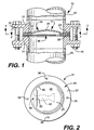
- FIGURE 1 is a side cross-sectional view of a reverse buckling rupture disk assembly of the present invention clamped between a pair of conventional pipe flanges.
- FIGURE 2 is a partial view taken along line 2-2 of FIG. 1.
- FIGURE 3 is a partial view taken along line 3-3 of FIG. 1.
- FIGURE 4 is a side cross-sectional view of the assembly of FIG. 1 illustrating the assembly after the rupture disk has reversed and ruptured.
- FIGURE 5(a) is a cross-sectional view of a rupture disk of the present invention, illustrating a cross section of the disk at the weakened area.
- FIGURE 5(b) is a cross-sectional view of a rupture disk before a weakened area is formed in the disk.
- FIGURE 5(c) is a cross-sectional view of a rupture disk having a prior art weakened area.
- FIGURE 6(a) is a cross-sectional view of a rupture disk of the present invention illustrating the support of the weakened area provided by the flange.
- FIGURE 6(b) is a cross-sectional view of a prior art rupture disk illustrating the unsupported weakened area.
- FIGURE 6(c) is a cross-sectional view of a prior art rupture disk illustrating a bending action that tends to occur at the weakened area.
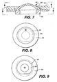
- FIGURE 7 is a side cross-sectional view of the improved reverse buckling rupture disk of this invention, including the tooling dies used to form the weakened area.
- FIGURE 8 is a top view taken along line 8-8 of FIG. 7.
- FIGURE 9 is a bottom view taken along line 9-9 of FIG 7.
-
- Referring now to the drawings, and particularly to FIGS. 1-4, a rupture disk assembly of the present invention including a reverse buckling rupture disk having an area of weakness defined therein is illustrated and generally designated by the numeral 10. As shown in FIG. 7, in this embodiment the area of weakness is in the form of a continuous C-shaped curve. The
assembly 10 is comprised of an inlet rupturedisk support member 12 and an outlet rupturedisk support member 14. A reverse buckling rupture disk and safety member assembly generally designated by the numeral 11 is shown clamped between thesupport members bolts 16. Thesupport member 12 is sealingly connected to aconduit 18 which is in turn connected to a vessel or system (not shown) containing pressurized fluid to be protected. Thesupport member 14 is sealingly connected to aconduit 20 which leads pressurized fluid relieved through therupture disk assembly 11 to a point of disposal, storage or the like. Although not shown,support members safety member assembly 11 is clamped between thesupport members gaskets - The
rupture disk assembly 11 of the present invention is comprised of arupture disk 28, such as the illustrated reverse buckling disk, and anannular safety member 36. Therupture disk 28 is preferably formed of a malleable material and has an area ofweakness 30 defined therein by an area or areas of material displaced by a partial shearing motion. As shown in FIG. 5(a) and as described more fully below, this partial shearing motion causes material displacement, but does not cut the disk. The area ofweakness 30 shown in FIGS. 1-4 in effect creates a continuous curved line of weakness along which the disk will tear, when subjected to a predetermined pressure differential. Therupture disk 28 is positioned adjacent to thegasket 24, which is in turn positioned adjacent to theinlet support member 12. Thesafety member 36 is positioned adjacent to therupture disk 28, and thegasket 26 is positioned between thesafety member 36 and theoutlet support member 14. Ifgaskets rupture disk 28 will contact the inlet support member and thesafety member 36 will contact the outlet support member. - As shown best in FIGS. 1 and 2, the
rupture disk 28 includes a convex-concave portion 25 connected to anannular flange portion 27. The convex-concave portion forms a convex surface in the side of therupture disk 28 adjacent theinlet support member 12 and a corresponding concave surface in the side adjacent theoutlet support member 14. The area ofweakness 30 formed by an area or areas of material displaced by a partial shearing movement in the reverse bucklingrupture disk 28 defines a substantially circular blow-outportion 48, which is connected to therupture disk 28 by anunweakened hinge area 50 between the opposite ends of the line ofweakness 30, i.e., thehinge area 50 corresponds to a chord of the substantially circular blow-outportion 48. - As shown in FIG. 3, the
safety member 36 is comprised of anannular ring 40. In the preferred embodiment, this annular ring is in immediate face-to-face contact with theflange portion 27 of the rupture disk. The inner diameter of theannular ring 40 preferably has a diameter that is just slightly less than the diameter of the C-shaped, curved line or area ofweakness 30, so that the disk upon rupture can freely open without interference. - In the presently preferred embodiment, three rupture initiating,
stress concentrating points 44 are provided on the inside edge of theannular ring 40 for contacting therupture disk 28 when it reverse buckles, but does not rupture. Thepoints 44 are formed by pairs of adjacent arcuate cut-outs 46 in thering 40. As shown in FIGS. 2 and 3, at least the reverse bucklingrupture disk 28 and thesafety member 36 are preferably attached together such as by means of spot welds 38. Theannular ring 40, the stress concentrating points, and the arcuate cut-outs 46 are configured in combination so that thestress concentrating points 44 will contact a portion of thearea 30 of weakness, should the disk reverse buckle but not immediately tear open. For example, if thereverse buckling disk 28 reverses but does not immediately tear along theareas 30 of weakness and the disk is subjected to increased pressure, the disk adjacent the concentratingpoints 44 will move or deform into the arcuate cut-outareas 46 and effectively force the intermediate portion into contact with the points, initiating tearing along the weakenedarea 30. - Preferably, the
safety member 36 includes a member to contact the disk upon reversal. In the presently preferred embodiment,catcher bar 42 is positioned adjacent thehinge area 50 and extends at least partially across the open interior of theoutlet support member 14. Upon reversal and rupture, thehinge area 50 of therupture disk 28 is supported and the blow-outportion 48 thereof is contacted and slowed down as it and the blow-outportion 48 bend into the open interior of thesupport member 14 as shown in FIG. 4. The support of thehinge area 50 and slowing down of the blow-outportion 48 of therupture disk 28 by thecatcher bar 42 prevent the blow-outportion 48 from fragmenting or tearing away from the remaining portion of therupture disk 28. - FIG. 5 provides a comparison of the prior art with the present invention. FIG. 5(b) represents a rupture disk having a
rupturable member 200 and aflange 202. FIG. 5(a) represents a disk formed according to the present invention. FIG. 5(c) represents a disk formed by prior art scoring techniques. - The improved reverse buckling rupture disk of the present invention has an area or areas of weakness defined therein by an area or areas of material displaced in a shear direction. The area is preferably formed by two die members which are slightly offset from each other, but have two edges which are almost aligned with each other, as shown in FIG. 7 and described in more detail below. As shown in FIG. 5(a), the rupture disk of the present invention can include a central
rupturable member 200 that will tear away from the rest of the disk at a predetermined pressure, the rupturable member including aperipheral edge 201. The disk further includes aflange 202 having an inner and outerperipheral edge area 205 formed between these peripheral edges and having a thickness less than the thickness of the flange and rupturable member. Depending upon the tooling used, the edges of the flange and rupturable member may be radiused. As shown in FIG. 7, bulges may be formed in areas adjacent to the weakened area as a result of material displacement. - In certain instances, the peripheral edge of the rupturable member will be substantially parallel to and substantially aligned with the inner peripheral edge of the flange. As shown in FIG. 5(a), the inner peripheral edge of the
flange 204 and the peripheral edge of therupturable member 201 are formed on opposite sides of the fluid passageway and are substantially aligned. The peripheral edge of the rupturable member may be formed on the inlet side and the inner peripheral edge of the flange is formed on the outlet side. Alternatively, the peripheral edge of the rupturable member may be formed on the outlet side, and the inner peripheral edge of the flange may be formed on the inlet side. - When a reverse buckling rupture disk is placed in operation, i.e., clamped between support members with pressurized fluid pressure exerted on the inlet side and atmospheric or a lower pressurized fluid pressure exerted on the outlet side, the rupture disk is placed in compression. Because the area of
weakness 205 in the rupture disk moved the disk material upwardly as shown in FIG. 6(a), the compressive forces are transmitted to theperipheral flange portion 202 of the disk, whereby the shear stress placed on the area or areas of material displaced by the partial shearing movement is relatively low. Thus, although the material of weakenedregion 205 is thinner than the remainder of the disk and hence will constitute the area at which the disk will open, the weakened region is nonetheless capable of withstanding pressure variations. It is therefore not necessary to support the weakened area of the rupture disk of the present invention. - In contrast to the present invention, the conventional, prior art scored rupture disk wherein a v-shaped notch is cut into the disk is illustrated in FIGS. 5(c), 6(b) and 6(c). The term "score" is used herein to mean a groove or notch formed in one side of a rupture disk by a knife blade or similar tool to produce a line of weakness in the rupture disk whereby upon failure of the rupture disk, it tears along the line of weakness. Referring to FIG. 5(c), the prior art scored reverse buckling
rupture disk 52 includes ascore 54 which is essentially a groove formed in one side of the disk. The remaining thin portion 56 of the disk material beneath thescore 54 connects the central blow-outportion 58 of the disk to theperipheral flange portion 60. Thescore 54 thus forms a line of weakness in the disk, and heretofore, one or more such scores have been utilized to form circular and other shaped blow-out portions connected by unweakened hinge portions in reverse buckling rupture disks. - As mentioned, when such prior art disks are subjected to pressure cycling, the disks often may fail as a result of stress applied to the thin portion 56 of disk material beneath the
score 54. It has been preferable to support the scored region of such prior art disks. Even with such support, the forces from the disk can cause a bending action at the score line, which may cause fatigue failure. As best seen in FIGS. 6(b) and 6(c), the forces transmitted from blow-outportion 58 are represented byarrow 59. These forces tend to cause a bending action as depicted in FIG. 6(c) when the pressure on the disk varies. - The present invention substantially minimizes or avoids the bending action seen in prior art disks as a result of the scoring method. In accordance with the present invention, one or more areas of weakness are defined in a reverse buckling rupture disk by an area or areas of material displaced by a partial shearing motion. The area(s) of weakness can be formed at the periphery of the rupturable member or in the main body of the member in a manner similar to cross scoring. These areas are capable of linearly accepting compression forces and carrying the forces or force vectors directly along a line from the rupturable member to the supporting flange of the disk.
- The method and dies used for forming an area or areas of material displaced by the partial shearing motion in a rupture disk of this invention are illustrated in FIGS. 7-9. FIG. 7 illustrates the die 66 in the process of forming the weakened area. The weakened area includes a thinner cross section than the remainder of the disk as a result of having material displaced in a shear direction. The degree of displacement can vary depending on the desired cross section in the weakened area. The method of the present invention is believed to be capable of providing a weakened area of thinner cross section than conventional scoring techniques because it does not have the problem of work-hardened material forming under the score blade.
- As illustrated in FIGS. 7-9, an area of weakness, generally designated by the numeral 64, can be formed in a
rupture disk 62 by a pair of dies 66 and 68 connected to appropriate tooling (not shown). In the presently preferred embodiment, thedie 66 is an annular ring utilized to stamp the area or areas of material displaced by the partial shearing movement into therupture disk 62. Thedie 68 is a second annular ring having an inside diameter slightly larger than the outside diameter ofdie 66. In this embodiment, the faces of the dies are parallel and almost in alignment with each other. Thedie 68 holds the rupture disk in place during the stamping operation. As shown, the dies 66 and 68 are preferably offset whereby they do not collide if the weakenedregion 64 is formed too deeply. Thus, the method of the present invention for forming an area or areas of weakness in a rupture disk along which the disk ruptures is an improvement over prior art methods whereby the dies used can and do collide. For example, the tooling utilized for forming thescore 54 in therupture disk 52 illustrated in FIG. 5(c) includes dies which oppose each other similar to the dies illustrated in U.S. Patents Nos. 4,441,350 and 4,458,516 cited above. If thescore 54 is formed too deeply, the dies collide causing damage to the dies and sometimes to the tooling connected to the dies. - Referring again to FIGS. 1-4, in operation of the
rupture disk assembly 10, pressurized fluid pressure from a vessel or system being protected is conducted to therupture disk 28 by theinlet support member 12, but it is contained and prevented from entering the open interior of theoutlet support member 14 by therupture disk 28 so long as the pressure does not exceed the design rupture pressure of therupture disk 28. The term "design rupture pressure" is used herein to mean that fluid pressure exerted on the convex side of the rupture disk at which therupture disk 28 is designed to reverse buckling and rupture. - When the fluid pressure exerted on the rupture exceeds the design rupture pressure of the
rupture disk 28, the disk reverse buckles and then tears in the area or areas ofweakness 30 defined by the area or areas of material displaced in a shear direction. When the blow-outportion 48 opens as a result of the rupture of thedisk 28, it is forced downward by the pressurized fluid being relieved through thedisk 28 into contact with thecatcher bar 42 of thesafety member 36. As illustrated in FIG. 4, the catcher bar reinforces thehinge area 50 so that as thehinge area 50 bends, the blow-outportion 48 does not tear away at the hinge area. Also, the extended portion of thecatcher bar 42 contacts and "catches" the blow-out portion whereby its movement downward is slowed down and fragmentation of the blow-outportion 50 does not result. It is contemplated that members other than the catcher bar can form a part ofsafety member 36 to perform the same function. - As mentioned above, because the area of material displaced in a shear direction is not placed in appreciable stress during pressure cycling, the
rupture disk 28 has a longer service life than comparable prior art reverse buckling rupture disks. - The rupture of the
disk 28 is assured by thesafety member 36. That is, the rupture initiating,stress concentrating points 44 provided on the interior edge of thesafety member 36 will contact a portion of the weakenedarea 30 and cause therupture disk 28 to rupture in the area or areas ofweakness 30 when the concave-convex portion of thedisk 28 reverses and is bent over thepoints 44 by fluid pressure. - As is well understood by those skilled in the art, when a reverse buckling rupture disk reverses without rupturing, it can resist rupture up to dangerous high fluid pressures because of having high tensile strength. Generally, a reverse buckling rupture disk must be designed to rupture in tension after reversal at a fluid pressure no greater than 1.5 times the design rupture pressure of the disk to assure the safe operation of the disk. The
safety member 36, with its cut outs and stress concentration points, is designed to assure that therupture disk 28 ruptures in tension at such a safe pressure level, if it reverses without rupture. - As will be understood, the area or areas of weakness formed by an area or areas of material displaced in a shear direction in the rupture disk of this invention can define blow-out portions of various geometric shapes as dictated by design criteria.
- The method of producing a rupture disk of the present invention which includes an area or areas of weakness along which the rupture disk ruptures comprises the steps of forming a rupturable member of malleable material having a pressurized fluid inlet side and an outlet side and adapted to be sealingly engaged in a pressurized fluid passageway. At least one area of material displaced by a partial shearing movement is formed to constitute an area of weakness in the rupture member. In a presently preferred embodiment, a male/female die set is used to form the area of displaced material. A die block is moved in a stamping or equivalent operation into contact with the disk. As shown in FIG. 7, the displacement of material by
die block 66 is done in a partial shearing motion caused by the motion of the rupture disk dome relative to the disk flange. The resulting area includes a thinner cross-sectional area that will facilitate opening of the disk. In the instance of a domed rupture disk such as shown in FIG. 7, the thinned area is capable of withstanding pressure variations because of an arch-like connection of the dome, weakened area, and flange. - The area or areas of material displaced by the partial shearing movement are formed in the rupture disk in a configuration which forms an area or areas of weakness defining a blow-out portion in the rupture disk. The rupture disk preferably also includes an unweakened hinge area connected to the blow-out portion. As mentioned above, the blow-out portion defined by the area of weakness can take a variety of shapes, but is preferably circular.
- The method of the present invention for assuring that a reverse buckling rupture disk having an area or areas of weakness formed therein ruptures after reverse buckling comprises placing an annular safety member adjacent to the rupture disk on the outlet side thereof which has at least one rupture initiating, stress concentrating point positioned to contact the rupture disk at the weakened region.
Claims (12)
- Reverse buckling rupture disk (28) comprising a rupturable member (200) having a concave-convex shape, a flange (202) having a substantially circular shape and being adapted for a sealing engagement in a pressurized fluid passageway, and at least one weakened region (205) formed in or adjacent to the rupturable member (200) such that it defines a blow-out portion (48) for opening of the rupturable member (200) in response to pressurized fluid, wherein further the blow-out portion (48) is connected to the flange (202) by an unweakened hinge area (50), wherein the rupturable member (200) is displaced relative to the flange (202) toward the inlet side of the disk (28) characterized in that the weakened region (205) has material displaced in a shear direction to thereby form a thinner cross section than the rupturable member (200).
- The rupture disk of claim 1, wherein said rupturable member (200) is circular and wherein said blow-out portion (48) is substantially circular and said hinge area (50) corresponds to a chord of said blow-out portion (48).
- The rupture disk of claim 1, wherein said blow-out portion (48) includes a generally concave-convex shape.
- The rupture disk of claim 1, wherein the annular flange (202) is connected to the rupturable member (200) by said weakened region (205) in a manner that the flange (202) supports the weakened region (205).
- The rupture disk of claim 1, wherein the flange (202) has an inner and outer peripheral edge (204, 203) and wherein the rupturable member (200) includes a peripheral edge (201), and wherein said flange (202) is offset from the rupturable member (200) to form the area of weakness (205) such that the peripheral edge (201) of the rupturable member (200) and the inner peripheral edge (203) of the flange (202) are exposed.
- The rupture disk of claim 5, wherein the peripheral edge (201) of the rupturable member (200) is substantially parallel to the inner peripheral edge (201) of the flange (202).
- The rupture disk of claim 5, wherein the peripheral edge (201) of the rupturable member (200) is substantially aligned with the inner peripheral edge (201) of the flange (202).
- A method of producing a reverse buckling rupture disk (28) having an area of weakness (205) along which said rupture disk ruptures, the method comprising forming a rupturable member (200) of malleable material having a concave-convex shape including a pressurized fluid inlet side and an outlet side, the rupture disk (28) including a flange (202) having a substantially circular shape and being adapted to be sealingly engaged in a pressurized fluid passageway, and forming an area of weakness (205), wherein the area of weakness (205) is formed by displacing an area of material in said rupturable member (200) with a partial shearing motion, said displacement of material causing a thinning in the cross section of the weakened area (205), leaving an unweakened hinge area (50) for connecting the flange (202) to a blow-out portion (48).
- The method of claim 8, wherein the partial shearing motion is in a direction perpendicular to the flange (202).
- The method of claim 8 or 9, wherein the displacement of material is caused by contacting the surface of the rupturable member (200) with a die (66) and moving the rupturable member (200) surface relative to the flange (202).
- The method of claim 10, wherein the displacement of material causes the flange (202) to be offset from the rupturable member (200) such that a portion of a peripheral edge (201) of the rupturable member (200) and a portion of an inner peripheral edge (203) of the flange (202) are exposed on opposite sides of the fluid passageway.
- The method of claim 11, wherein the peripheral edge (201) of the rupturable member (200) and the inner peripheral edge (203) of the flange (202) are substantially aligned.
Priority Applications (1)
| Application Number | Priority Date | Filing Date | Title |
|---|---|---|---|
| EP03013573A EP1347222B1 (en) | 1995-10-24 | 1996-10-23 | Rupture disk apparatus |
Applications Claiming Priority (2)
| Application Number | Priority Date | Filing Date | Title |
|---|---|---|---|
| US08/547,311 US5934308A (en) | 1995-10-24 | 1995-10-24 | Rupture disk apparatus and methods |
| US547311 | 1995-10-24 |
Related Child Applications (1)
| Application Number | Title | Priority Date | Filing Date |
|---|---|---|---|
| EP03013573A Division EP1347222B1 (en) | 1995-10-24 | 1996-10-23 | Rupture disk apparatus |
Publications (3)
| Publication Number | Publication Date |
|---|---|
| EP0770805A2 EP0770805A2 (en) | 1997-05-02 |
| EP0770805A3 EP0770805A3 (en) | 1999-01-20 |
| EP0770805B1 true EP0770805B1 (en) | 2005-08-10 |
Family
ID=24184187
Family Applications (2)
| Application Number | Title | Priority Date | Filing Date |
|---|---|---|---|
| EP03013573A Expired - Lifetime EP1347222B1 (en) | 1995-10-24 | 1996-10-23 | Rupture disk apparatus |
| EP96117017A Expired - Lifetime EP0770805B1 (en) | 1995-10-24 | 1996-10-23 | Rupture disk apparatus and methods |
Family Applications Before (1)
| Application Number | Title | Priority Date | Filing Date |
|---|---|---|---|
| EP03013573A Expired - Lifetime EP1347222B1 (en) | 1995-10-24 | 1996-10-23 | Rupture disk apparatus |
Country Status (7)
| Country | Link |
|---|---|
| US (4) | US5934308A (en) |
| EP (2) | EP1347222B1 (en) |
| JP (1) | JPH09178076A (en) |
| CN (1) | CN1089415C (en) |
| CA (1) | CA2188229A1 (en) |
| DE (1) | DE69635041T2 (en) |
| IN (1) | IN191054B (en) |
Cited By (1)
| Publication number | Priority date | Publication date | Assignee | Title |
|---|---|---|---|---|
| US8414788B2 (en) | 2005-04-01 | 2013-04-09 | Fike Corporation | Reverse acting rupture disc with laser-defined electropolished line of weakness and method of forming the line of weakness |
Families Citing this family (46)
| Publication number | Priority date | Publication date | Assignee | Title |
|---|---|---|---|---|
| US5996696A (en) * | 1997-06-27 | 1999-12-07 | Fike Corporation | Method and apparatus for testing the integrity of oil delivery tubing within an oil well casing |
| US6006938A (en) | 1997-09-18 | 1999-12-28 | Continental Disc Corporation | Enhanced reverse buckling rupture disc |
| DE19853080A1 (en) * | 1998-11-17 | 2000-05-18 | Trw Airbag Sys Gmbh & Co Kg | Opening burst disc on pressure container for vehicle occupant restraint system involves applying arc discharge to linear interaction zone between electrode and surface of closure disc |
| DE69926360T2 (en) * | 1999-03-15 | 2006-05-24 | Continental Disc Corp. | Reverse Buckling |
| EP1710479B1 (en) | 1999-05-13 | 2012-02-08 | BS & B Safety Systems Limited | Rupture disk assembly |
| US6178983B1 (en) | 1999-05-13 | 2001-01-30 | Bs&B Safety Systems, Inc. | Rupture disk assembly |
| US6298869B1 (en) * | 2000-02-24 | 2001-10-09 | Oklahoma Safety Equipment Co. | Reverse buckling, thermoformed, polymer rupture disk |
| US6311715B1 (en) | 2000-07-07 | 2001-11-06 | Zook Enterprises, Llc | Stacked rupture disk assembly |
| US6948515B2 (en) * | 2000-07-07 | 2005-09-27 | Zook Enterprises, Llc | Carbon rupture disk assembly |
| DE10056023A1 (en) * | 2000-11-11 | 2002-06-13 | Opel Adam Ag | Sheet component with post-molding removable sector has at least one slot in predetermined sector to prepare access to fixing device |
| JP4113921B2 (en) * | 2002-01-09 | 2008-07-09 | 新キャタピラー三菱株式会社 | Method and apparatus for manufacturing anti-slip material in construction machine |
| US6983758B2 (en) * | 2002-07-05 | 2006-01-10 | Rohm And Haas Company | Prevention of unwanted material accumulations |
| US7017767B2 (en) * | 2003-11-13 | 2006-03-28 | Fike Corporation | Non-fragmenting pressure relief apparatus |
| US6959828B2 (en) * | 2003-11-13 | 2005-11-01 | Fike Corporation | Non-fragmenting pressure relief apparatus |
| KR101094772B1 (en) * | 2004-06-30 | 2011-12-16 | 엘지디스플레이 주식회사 | Tiled display device |
| US7520153B2 (en) * | 2006-05-13 | 2009-04-21 | Rembe Gmbh | Bursting disk and method for manufacturing the same |
| US20080006389A1 (en) * | 2006-06-27 | 2008-01-10 | Ioan Sauciuc | Preventing burst-related hazards in microelectronic cooling systems |
| EP2049821A4 (en) | 2006-07-21 | 2013-09-04 | Amgen Inc | Rupture valve |
| US20080060702A1 (en) * | 2006-09-12 | 2008-03-13 | Scott Muddiman | Elliptical score pattern for reverse acting style rupture disc and assembly using the same |
| JP4537988B2 (en) * | 2006-11-07 | 2010-09-08 | 佐藤工業株式会社 | Gas dissolved water production mixer and gas dissolved water production apparatus |
| US8122747B2 (en) * | 2008-06-03 | 2012-02-28 | Stolle Machinery Company, Llc | Can end scoring method, and tooling assembly and conversion press therefor |
| US7878215B2 (en) * | 2008-11-21 | 2011-02-01 | Fike Corporation | Impulse actuated valve |
| US8636164B2 (en) * | 2008-12-10 | 2014-01-28 | Continental Disc Corporation | Controlling the rated burst pressure of a rupture disc through the use of control scores on the disc dome |
| US20100140238A1 (en) * | 2008-12-10 | 2010-06-10 | Continental Disc Corporation | Machining score lines in a rupture disc using laser machining |
| DE202009001389U1 (en) | 2009-02-05 | 2009-04-09 | Basf Se | Rupture disk and device for mounting a rupture disk |
| US8656823B2 (en) * | 2009-06-05 | 2014-02-25 | Fox Factory, Inc. | Methods and apparatus for suspending a vehicle shield |
| JP2013506802A (en) * | 2009-09-30 | 2013-02-28 | ビーエス アンド ビー セイフティー システムズ リミテッド | Rupture disc |
| US8387647B1 (en) * | 2010-05-18 | 2013-03-05 | Oklahoma Safety Equipment Company, Inc. | Overpressure indicating reverse buckling disk apparatus |
| US8354934B2 (en) | 2010-06-14 | 2013-01-15 | Fike Corporation | Burst indicator |
| DK2532933T3 (en) * | 2011-06-09 | 2022-06-07 | Rembe Gmbh Safety Control | Apparatus for limiting the opening angle of a fracture disc |
| EP2756214B1 (en) | 2011-09-16 | 2017-03-08 | BS & B Safety Systems Limited | Rupture disk and hinge |
| CA2864282C (en) | 2012-02-14 | 2020-07-07 | Bs&B Safety Systems Limited | Quality control for a pressure relief device |
| CN103423495B (en) * | 2012-05-15 | 2016-05-04 | 南通中集罐式储运设备制造有限公司 | Blasting piece device, warehousing and transportation facilities and blasting piece device preparation method |
| US9551429B2 (en) * | 2012-07-18 | 2017-01-24 | Fike Corporation | Rupture disc having laser-defined reversal initiation and deformation control features |
| CN102954262A (en) * | 2012-11-19 | 2013-03-06 | 大连理工大学 | Deflagration overpressure relief device with wave adsorption and flame suppression functions |
| GB201303611D0 (en) * | 2013-02-28 | 2013-04-17 | Airbus Operations Ltd | Aircraft fuel tank arrangement |
| EP2989359B1 (en) * | 2013-04-25 | 2017-11-08 | BS&B Innovation Limited | Frustum-shaped rupture disk having line of weakness |
| FR3027647B1 (en) * | 2014-10-24 | 2016-12-09 | Commissariat Energie Atomique | BREAK DISC FOR A DEVICE FOR PROTECTING AGAINST SURPRESSIONS IN THE INTERIOR OF EQUIPMENT, APPLICATION TO EQUIPMENT INTENDED TO CONTAIN SUCCESSIVELY TWO GASES OF A DIFFERENT CHEMICAL NATURE |
| CN105003698A (en) * | 2015-07-29 | 2015-10-28 | 北京矿大节能科技有限公司 | High-temperature-resistance anti-explosion valve and work method thereof |
| US10100942B2 (en) * | 2016-08-19 | 2018-10-16 | Continental Disc Corporation | Inlet support structure for a tension acting rupture disc |
| EP3504468B1 (en) | 2016-08-29 | 2023-10-04 | BS&B Innovations Limited | Pressure relief module |
| CN107044552A (en) * | 2017-01-19 | 2017-08-15 | 北京航空航天大学 | Filtering type diaphragm valve |
| US10139027B1 (en) * | 2017-07-06 | 2018-11-27 | Martin Engineering Company | Flange assembly with frangible gate for mounting air cannons to bulk material processing equipment |
| JP7359771B2 (en) | 2017-10-12 | 2023-10-11 | ビーエス アンド ビー イノベーションズ リミテッド | rupture disc |
| AU2019297345A1 (en) * | 2018-07-05 | 2021-01-21 | Fike Corporation | Rupture disc having stress concentrating feature |
| WO2022195519A1 (en) * | 2021-03-17 | 2022-09-22 | Bs&B Innovations Limited | Kinetic hinge for a pressure relief device |
Family Cites Families (26)
| Publication number | Priority date | Publication date | Assignee | Title |
|---|---|---|---|---|
| US2159325A (en) * | 1935-09-30 | 1939-05-23 | Guardian Safety Seal Company | Method of rendering sheet metal and sheet metal articles readily severable |
| US3929251A (en) * | 1972-08-17 | 1975-12-30 | Aluminum Co Of America | Container wall with rupturable weakening line |
| US3834580A (en) * | 1972-09-25 | 1974-09-10 | Black Sivalls & Bryson Inc | Safety pressure relief device |
| US3997076A (en) * | 1974-05-02 | 1976-12-14 | Aluminum Company Of America | Tabless container opening device |
| US3921556A (en) * | 1975-01-02 | 1975-11-25 | Black Sivalls & Bryson Inc | Scored reverse buckling rupture disk manufacturing method |
| US4043481A (en) * | 1975-07-16 | 1977-08-23 | Continental Can Company, Inc. | Scored metal flap areas |
| US4211334A (en) * | 1977-09-12 | 1980-07-08 | B S & B Safety Systems, Inc. | Safety pressure relief apparatus |
| US4158422A (en) * | 1977-09-12 | 1979-06-19 | Black, Sivalls & Bryson, Inc. | Safety pressure relief apparatus |
| US4269214A (en) | 1979-01-19 | 1981-05-26 | Bs & B Safety Systems, Inc. | Safety pressure relief device |
| US4216736A (en) * | 1979-02-02 | 1980-08-12 | Boise Cascade Corporation | Method and apparatus for forming no-fin scored metal ends |
| US4236648A (en) * | 1979-03-05 | 1980-12-02 | Black, Sivalls & Bryson | Safety pressure relief apparatus |
| US4513874A (en) * | 1980-07-16 | 1985-04-30 | Sexton Can Company, Inc. | Pressure relief device for internally pressurized fluid container |
| CA1156569A (en) * | 1980-07-16 | 1983-11-08 | Walter J. Mulawski | Pressure relief device for internally pressurized fluid container |
| US4347942A (en) * | 1980-11-24 | 1982-09-07 | Pressure-Pak Container Co., Inc. | Pressure relief device and method of fabrication thereof |
| US4441350A (en) | 1981-12-15 | 1984-04-10 | Bs&B Safety Systems, Inc. | Scored reverse buckling rupture disk manufacturing method |
| GB2126281A (en) * | 1982-07-21 | 1984-03-21 | Johnson Matthey Plc | Pressure relieving devices |
| US4458516A (en) | 1983-02-11 | 1984-07-10 | Bs&B Safety Systems, Inc. | Method for manufacturing rupture disks |
| US4492103A (en) * | 1983-02-11 | 1985-01-08 | Bs&B Safety Systems, Inc. | Apparatus for manufacturing rupture disks |
| US4479587A (en) * | 1983-09-06 | 1984-10-30 | Bs&B Safety Systems, Inc. | Two-way rupturable pressure relief apparatus |
| US4759460A (en) * | 1983-09-20 | 1988-07-26 | Continental Disc Corporation | Rupture disc system |
| US4597505A (en) * | 1984-04-09 | 1986-07-01 | Continental Disc Corporation | Rupture disc with selectively positioned initial buckling |
| US4738372A (en) * | 1985-11-21 | 1988-04-19 | Pressure Pak, Inc. | Method and device for corrosion relief of a pressure vessel |
| CA2012964C (en) | 1990-01-09 | 1998-06-16 | Edward H. Short Iii | Scored reverse buckling rupture disk assembly |
| US5005722A (en) * | 1990-11-07 | 1991-04-09 | Bs&B Safety Systems, Inc. | Fail safe rupture disk assembly |
| US5082133A (en) * | 1991-08-01 | 1992-01-21 | Bs&B Safety Systems, Inc. | Low pressure rupture disk and assembly |
| US5368180A (en) * | 1993-10-12 | 1994-11-29 | Bs&B Safety Systems, Inc. | Perforated rupture disk assembly |
-
1995
- 1995-10-24 US US08/547,311 patent/US5934308A/en not_active Expired - Lifetime
-
1996
- 1996-10-18 CA CA002188229A patent/CA2188229A1/en not_active Abandoned
- 1996-10-23 DE DE69635041T patent/DE69635041T2/en not_active Expired - Lifetime
- 1996-10-23 EP EP03013573A patent/EP1347222B1/en not_active Expired - Lifetime
- 1996-10-23 IN IN1852CA1996 patent/IN191054B/en unknown
- 1996-10-23 EP EP96117017A patent/EP0770805B1/en not_active Expired - Lifetime
- 1996-10-24 JP JP8299258A patent/JPH09178076A/en active Pending
- 1996-10-24 CN CN96121639A patent/CN1089415C/en not_active Expired - Fee Related
-
1998
- 1998-01-08 US US09/004,503 patent/US5996605A/en not_active Expired - Lifetime
- 1998-01-08 US US09/004,504 patent/US5974851A/en not_active Expired - Lifetime
-
1999
- 1999-09-20 US US09/399,945 patent/US6192914B1/en not_active Expired - Lifetime
Cited By (1)
| Publication number | Priority date | Publication date | Assignee | Title |
|---|---|---|---|---|
| US8414788B2 (en) | 2005-04-01 | 2013-04-09 | Fike Corporation | Reverse acting rupture disc with laser-defined electropolished line of weakness and method of forming the line of weakness |
Also Published As
| Publication number | Publication date |
|---|---|
| EP0770805A2 (en) | 1997-05-02 |
| JPH09178076A (en) | 1997-07-11 |
| IN191054B (en) | 2003-09-13 |
| US6192914B1 (en) | 2001-02-27 |
| DE69635041D1 (en) | 2005-09-15 |
| US5996605A (en) | 1999-12-07 |
| CN1158393A (en) | 1997-09-03 |
| US5934308A (en) | 1999-08-10 |
| US5974851A (en) | 1999-11-02 |
| EP1347222A2 (en) | 2003-09-24 |
| EP0770805A3 (en) | 1999-01-20 |
| CA2188229A1 (en) | 1997-04-25 |
| EP1347222B1 (en) | 2011-08-24 |
| DE69635041T2 (en) | 2006-04-13 |
| EP1347222A3 (en) | 2006-03-08 |
| CN1089415C (en) | 2002-08-21 |
Similar Documents
| Publication | Publication Date | Title |
|---|---|---|
| EP0770805B1 (en) | Rupture disk apparatus and methods | |
| US6494074B2 (en) | Rupture disk assembly | |
| US6321582B1 (en) | Method and apparatus for forming a rupture disk | |
| EP0437019B1 (en) | Scored reverse buckling rupture disk assembly | |
| US6241113B1 (en) | Enhanced reverse buckling rupture disc | |
| US4759460A (en) | Rupture disc system | |
| US4146047A (en) | Integral fluid pressure rupturable apparatus | |
| US4838447A (en) | Pressure relief device with conical reverse buckling disc | |
| US5558114A (en) | Eccentric scored rupture disk assembly | |
| US5305775A (en) | Apparatus and method for preventing fragmentation of a rupture disk | |
| GB2133083A (en) | Scored rupture disk apparatus | |
| US5413237A (en) | Nonfragmenting rupture disk assemblies and methods | |
| EP1078183B1 (en) | Enhanced reverse buckling rupture disc |
Legal Events
| Date | Code | Title | Description |
|---|---|---|---|
| PUAI | Public reference made under article 153(3) epc to a published international application that has entered the european phase |
Free format text: ORIGINAL CODE: 0009012 |
|
| AK | Designated contracting states |
Kind code of ref document: A2 Designated state(s): DE FR GB IE IT NL |
|
| PUAL | Search report despatched |
Free format text: ORIGINAL CODE: 0009013 |
|
| AK | Designated contracting states |
Kind code of ref document: A3 Designated state(s): DE FR GB IE IT NL |
|
| 17P | Request for examination filed |
Effective date: 19990713 |
|
| 17Q | First examination report despatched |
Effective date: 20020422 |
|
| GRAP | Despatch of communication of intention to grant a patent |
Free format text: ORIGINAL CODE: EPIDOSNIGR1 |
|
| RAP1 | Party data changed (applicant data changed or rights of an application transferred) |
Owner name: BS & B SAFETY SYSTEMS LIMITED |
|
| GRAS | Grant fee paid |
Free format text: ORIGINAL CODE: EPIDOSNIGR3 |
|
| GRAA | (expected) grant |
Free format text: ORIGINAL CODE: 0009210 |
|
| AK | Designated contracting states |
Kind code of ref document: B1 Designated state(s): DE FR GB IE IT NL |
|
| REG | Reference to a national code |
Ref country code: GB Ref legal event code: FG4D |
|
| REG | Reference to a national code |
Ref country code: IE Ref legal event code: FG4D |
|
| REF | Corresponds to: |
Ref document number: 69635041 Country of ref document: DE Date of ref document: 20050915 Kind code of ref document: P |
|
| ET | Fr: translation filed | ||
| PLBE | No opposition filed within time limit |
Free format text: ORIGINAL CODE: 0009261 |
|
| STAA | Information on the status of an ep patent application or granted ep patent |
Free format text: STATUS: NO OPPOSITION FILED WITHIN TIME LIMIT |
|
| 26N | No opposition filed |
Effective date: 20060511 |
|
| PGFP | Annual fee paid to national office [announced via postgrant information from national office to epo] |
Ref country code: IE Payment date: 20130902 Year of fee payment: 18 |
|
| PGFP | Annual fee paid to national office [announced via postgrant information from national office to epo] |
Ref country code: NL Payment date: 20141226 Year of fee payment: 19 |
|
| REG | Reference to a national code |
Ref country code: IE Ref legal event code: MM4A |
|
| REG | Reference to a national code |
Ref country code: FR Ref legal event code: PLFP Year of fee payment: 20 |
|
| PG25 | Lapsed in a contracting state [announced via postgrant information from national office to epo] |
Ref country code: IE Free format text: LAPSE BECAUSE OF NON-PAYMENT OF DUE FEES Effective date: 20141023 |
|
| PGFP | Annual fee paid to national office [announced via postgrant information from national office to epo] |
Ref country code: IT Payment date: 20151026 Year of fee payment: 20 Ref country code: GB Payment date: 20151027 Year of fee payment: 20 Ref country code: DE Payment date: 20151028 Year of fee payment: 20 |
|
| PGFP | Annual fee paid to national office [announced via postgrant information from national office to epo] |
Ref country code: FR Payment date: 20151019 Year of fee payment: 20 |
|
| REG | Reference to a national code |
Ref country code: NL Ref legal event code: MM Effective date: 20151101 |
|
| PG25 | Lapsed in a contracting state [announced via postgrant information from national office to epo] |
Ref country code: NL Free format text: LAPSE BECAUSE OF NON-PAYMENT OF DUE FEES Effective date: 20151101 |
|
| REG | Reference to a national code |
Ref country code: DE Ref legal event code: R071 Ref document number: 69635041 Country of ref document: DE |
|
| REG | Reference to a national code |
Ref country code: GB Ref legal event code: PE20 Expiry date: 20161022 |
|
| PG25 | Lapsed in a contracting state [announced via postgrant information from national office to epo] |
Ref country code: GB Free format text: LAPSE BECAUSE OF EXPIRATION OF PROTECTION Effective date: 20161022 |