EP0770780B1 - Kreiselpumpenaggregat mit einer Magnetkupplung - Google Patents
Kreiselpumpenaggregat mit einer Magnetkupplung Download PDFInfo
- Publication number
- EP0770780B1 EP0770780B1 EP96116129A EP96116129A EP0770780B1 EP 0770780 B1 EP0770780 B1 EP 0770780B1 EP 96116129 A EP96116129 A EP 96116129A EP 96116129 A EP96116129 A EP 96116129A EP 0770780 B1 EP0770780 B1 EP 0770780B1
- Authority
- EP
- European Patent Office
- Prior art keywords
- magnetic coupling
- centrifugal pump
- pump
- heat exchanger
- shaft
- Prior art date
- Legal status (The legal status is an assumption and is not a legal conclusion. Google has not performed a legal analysis and makes no representation as to the accuracy of the status listed.)
- Expired - Lifetime
Links
- 230000008878 coupling Effects 0.000 title claims description 37
- 238000010168 coupling process Methods 0.000 title claims description 37
- 238000005859 coupling reaction Methods 0.000 title claims description 37
- 239000012526 feed medium Substances 0.000 claims 1
- 239000002609 medium Substances 0.000 claims 1
- 239000012530 fluid Substances 0.000 description 8
- 239000007788 liquid Substances 0.000 description 7
- 238000010438 heat treatment Methods 0.000 description 5
- 238000001816 cooling Methods 0.000 description 4
- 238000004804 winding Methods 0.000 description 3
- 230000000694 effects Effects 0.000 description 2
- 238000003889 chemical engineering Methods 0.000 description 1
- 239000002826 coolant Substances 0.000 description 1
- 230000006735 deficit Effects 0.000 description 1
- 230000006866 deterioration Effects 0.000 description 1
- 238000004519 manufacturing process Methods 0.000 description 1
- 238000010327 methods by industry Methods 0.000 description 1
- 230000002035 prolonged effect Effects 0.000 description 1
- 238000005086 pumping Methods 0.000 description 1
- 230000000284 resting effect Effects 0.000 description 1
- 238000009420 retrofitting Methods 0.000 description 1
- 239000000126 substance Substances 0.000 description 1
- 238000010792 warming Methods 0.000 description 1
Images
Classifications
-
- H—ELECTRICITY
- H02—GENERATION; CONVERSION OR DISTRIBUTION OF ELECTRIC POWER
- H02K—DYNAMO-ELECTRIC MACHINES
- H02K15/00—Processes or apparatus specially adapted for manufacturing, assembling, maintaining or repairing of dynamo-electric machines
- H02K15/12—Impregnating, moulding insulation, heating or drying of windings, stators, rotors or machines
- H02K15/125—Heating or drying of machines in operational state, e.g. standstill heating
-
- F—MECHANICAL ENGINEERING; LIGHTING; HEATING; WEAPONS; BLASTING
- F04—POSITIVE - DISPLACEMENT MACHINES FOR LIQUIDS; PUMPS FOR LIQUIDS OR ELASTIC FLUIDS
- F04D—NON-POSITIVE-DISPLACEMENT PUMPS
- F04D13/00—Pumping installations or systems
- F04D13/02—Units comprising pumps and their driving means
- F04D13/021—Units comprising pumps and their driving means containing a coupling
- F04D13/024—Units comprising pumps and their driving means containing a coupling a magnetic coupling
-
- F—MECHANICAL ENGINEERING; LIGHTING; HEATING; WEAPONS; BLASTING
- F04—POSITIVE - DISPLACEMENT MACHINES FOR LIQUIDS; PUMPS FOR LIQUIDS OR ELASTIC FLUIDS
- F04D—NON-POSITIVE-DISPLACEMENT PUMPS
- F04D29/00—Details, component parts, or accessories
- F04D29/58—Cooling; Heating; Diminishing heat transfer
- F04D29/586—Cooling; Heating; Diminishing heat transfer specially adapted for liquid pumps
- F04D29/5866—Cooling at last part of the working fluid in a heat exchanger
Definitions
- the invention relates to a centrifugal pump unit, the pump part of a Shaft connection is driven by an electric motor, with one between the Electric motor and the centrifugal pump arranged magnetic coupling, the primary part with the shaft of the electric motor and its secondary part with the shaft of Centrifugal pump is connected, the inside of the secondary part of the Magnetic coupling receiving, acted upon by the medium and from Can of the magnetic coupling enclosed by an interior Foreign medium flowing through the heat exchanger is arranged.
- Centrifugal pumps driven by magnetic clutches which also as Magnetic clutch pumps are hermetically sealed Pumping, since the rooms exposed to the pumped medium are only on surfaces resting against each other are sealed.
- the transfer of one Torque delivered to the motor is via permanent magnets attached to a the primary shaft connected to the motor shaft and on one with the pump shaft connected secondary part are arranged.
- Between primary and secondary part is the wall of a containment can, which is the one with the pump room connected interior of the magnetic coupling seals from the environment. Due to a gap flow of the liquid that comes from the pump room and returned to it, become part during pump operation the heat generated in the magnetic coupling is dissipated and that in the interior the magnetic coupling lubricated existing bearings.
- a particular problem for magnetic coupling pumps is the delivery media that are only liquid when hot, when cooling to the temperature, the atmosphere surrounding the magnetic coupling pump become viscous or even freeze.
- the media to be pumped must be started before the magnetic coupling pump is started up be put back in the liquid state so that they can maintain it necessary functions to function properly
- the heating and liquefaction of the fluid in the Hydraulic part of the centrifugal pump easily by means of a pump wall supplied heat output is the relative to the environment largely shielded inner part of the magnetic coupling is difficult for the necessary heat transfer achievable.
- a disadvantage of the design taught in DE-U-295 05 250 is that Need a special design with a fluid flow chamber equipped housing part, which due to the large space requirement on the entire Magnetic coupling and its design affects. Retrofitting one thus executed housing part is how to use the im Embodiment of the font shown voluminous bearing housing can hardly determine. A placed around an existing housing part or the pipe winding embedded in it would also take up a lot of space, would bring so the same problem with it. Another problem of the specifically taught Execution is that the heat transfer wall of the Bearing housing largely through the secondary part of the magnetic coupling is shielded. So the temperature on the wall of the heat exchanger can be controlled Liquid only through a narrow gap in the rest of the interior of the magnetic coupling.
- the invention has for its object to a magnetic clutch pump create their heat exchangers immediately, i.e. without impairment through any housing parts on the inside of the magnetic coupling located fluid acts and thus no reduction in performance causes.
- the object is achieved in that the heat exchanger a point of the interior is arranged as a free area opposite the Areas remain in which the secondary part of the magnetic coupling with this connected shaft of the centrifugal pump and its bearings are arranged ..
- the inside of the Magnetic coupling available space can be used optimally. This is especially true for a heat exchanger formed by a coil, the Windings can be optimally adapted to the given spatial conditions can.
- the invention is explained in more detail using an exemplary embodiment.
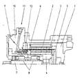
- the Drawing shows a partial section of a magnetic coupling in a centrifugal pump.
- a primary part 1 is firmly connected.
- the primary part 1 carries Magnets evenly distributed over the circumference 2.
- Concentric to the Magnets 2, magnets 3 are arranged on a secondary part 4.
- a containment shell 5 Between the Primary part 1 and the secondary part 4 is a containment shell 5, the one Interior 6 hermetically seals against the environment.
- the secondary part 4 is attached to a pump shaft 7, which at its Secondary part 4 opposite end carries - not shown - impeller.
- a pump shaft 7 which at its Secondary part 4 opposite end carries - not shown - impeller.
- Bearings of the pump shaft 7 serve slide bearings 8.
- Channels for an inlet 11 are in the housing cover 10 of the magnetic coupling pump and a drain (not shown) arranged on the opposite side provided with a heat exchanger arranged in the interior 6 12 are connected.
- the heat exchanger 12 consists of a or multiple coiled tube, but can also be any other to which Space in the interior 6 have an adapted shape.
- the heat exchanger 12 through which a liquid or vapor medium can perform two functions. For one, during the operation of the magnetic coupling pump of the heat exchanger 12 with a Fluid is fed, which has a temperature gradient to the liquid in the interior 6 has and therefore creates a cooling effect. On the other hand is about the heat exchanger 12 a hot medium feasible, which is part of its heat content to the medium located in the interior 6 and this, if it is by a Temperature reduction while the magnetic clutch pump is at a standstill should be frozen, liquefied again. The latter measure must be taken before restarting the magnetic clutch pump after a prolonged standstill.
Landscapes
- Engineering & Computer Science (AREA)
- Mechanical Engineering (AREA)
- General Engineering & Computer Science (AREA)
- Physics & Mathematics (AREA)
- Thermal Sciences (AREA)
- Manufacturing & Machinery (AREA)
- Power Engineering (AREA)
- Structures Of Non-Positive Displacement Pumps (AREA)
Description
Claims (2)
- Kreiselpumpenaggregat, dessen Pumpenteil über eine Wellenverbindung von einem Elektromotor angetrieben wird, mit einer zwischen dem Elektromotor und der Kreiselpumpe angeordneten Magnetkupplung, deren Primärteil mit der Welle des Elektromotors und deren Sekundärteil mit der Welle der Kreiselpumpe verbunden ist, wobei innerhalb des den Sekundärteil der Magnetkupplung aufnehmenden, vom Fördermedium beaufschlagten und vom Spalttopf der Magnetkupplung umschlossenen Innenraumes ein von einem Fremdmedium durchströmter Wärmeaustauscher angeordnet ist, dadurch gekennzeichnet, daß der Wärmeaustauscher (12) an einer Stelle des Innenraumes (6) angeordnet ist, die als freier Bereich gegenüber den Bereichen verbleibt, in welchen der Sekundärteil (4) der Magnetkupplung, die mit diesem verbundene Welle (7) der Kreiselpumpe und deren Lager (8) angeordnet sind.
- Kreiselpumpenaggregat nach Anspruch 1, dadurch gekennzeichnet, daß der Wärmeaustauscher (12) von einem einfach oder mehrfach gewickelten Rohr gebildet wird.
Applications Claiming Priority (2)
| Application Number | Priority Date | Filing Date | Title |
|---|---|---|---|
| DE19539878 | 1995-10-26 | ||
| DE19539878A DE19539878A1 (de) | 1995-10-26 | 1995-10-26 | Wärmeaustauscher für die Magnetkupplung einer Kreiselpumpe |
Publications (2)
| Publication Number | Publication Date |
|---|---|
| EP0770780A1 EP0770780A1 (de) | 1997-05-02 |
| EP0770780B1 true EP0770780B1 (de) | 2001-08-22 |
Family
ID=7775850
Family Applications (1)
| Application Number | Title | Priority Date | Filing Date |
|---|---|---|---|
| EP96116129A Expired - Lifetime EP0770780B1 (de) | 1995-10-26 | 1996-10-09 | Kreiselpumpenaggregat mit einer Magnetkupplung |
Country Status (2)
| Country | Link |
|---|---|
| EP (1) | EP0770780B1 (de) |
| DE (2) | DE19539878A1 (de) |
Families Citing this family (1)
| Publication number | Priority date | Publication date | Assignee | Title |
|---|---|---|---|---|
| DE10235473B4 (de) | 2002-08-02 | 2007-12-27 | Knorr-Bremse Systeme für Nutzfahrzeuge GmbH | Vorrichtung und Verfahren zum Aufrechterhalten des Niveaus einer Nutzebene eines Fahrzeugs |
Citations (1)
| Publication number | Priority date | Publication date | Assignee | Title |
|---|---|---|---|---|
| DE29505250U1 (de) * | 1995-03-28 | 1995-05-18 | Feodor Burgmann Dichtungswerke GmbH & Co, 82515 Wolfratshausen | Magnetkupplung |
Family Cites Families (2)
| Publication number | Priority date | Publication date | Assignee | Title |
|---|---|---|---|---|
| GB2167495B (en) * | 1984-11-20 | 1988-11-09 | Boc Group Plc | Improvements in mechanical pumps |
| DE3639719C3 (de) * | 1986-11-20 | 1994-02-24 | Hermetic Pumpen Gmbh | Spaltrohrmagnetpumpe |
-
1995
- 1995-10-26 DE DE19539878A patent/DE19539878A1/de not_active Withdrawn
-
1996
- 1996-10-09 DE DE59607527T patent/DE59607527D1/de not_active Expired - Lifetime
- 1996-10-09 EP EP96116129A patent/EP0770780B1/de not_active Expired - Lifetime
Patent Citations (1)
| Publication number | Priority date | Publication date | Assignee | Title |
|---|---|---|---|---|
| DE29505250U1 (de) * | 1995-03-28 | 1995-05-18 | Feodor Burgmann Dichtungswerke GmbH & Co, 82515 Wolfratshausen | Magnetkupplung |
Also Published As
| Publication number | Publication date |
|---|---|
| DE59607527D1 (de) | 2001-09-27 |
| EP0770780A1 (de) | 1997-05-02 |
| DE19539878A1 (de) | 1997-04-30 |
Similar Documents
| Publication | Publication Date | Title |
|---|---|---|
| DE3220448C1 (de) | Pumpenaggregat fuer Heizungs- und Brauchwasseranlagen | |
| EP1308504B1 (de) | Inkubations-und Lagervorrichtung, insbesondere für Proben aus organischem Material | |
| DE3135154A1 (de) | "waermepumpe" | |
| CH334061A (de) | Motorpumpenaggregat | |
| DE3639719A1 (de) | Spaltrohrmagnetpumpe | |
| EP0711692B1 (de) | Antriebseinheit mit einer Brennkraftmaschine und einem hydrodynamischen Retarder | |
| DE102011076140A1 (de) | Kühlmantel für Elektromotor | |
| DE2628589C3 (de) | Wärmetauscher | |
| DE2545304B2 (de) | Kältemaschine | |
| DE4212982C2 (de) | Pumpe für heiße Fördermedien | |
| DE4440163C2 (de) | Antriebseinheit mit einer Brennkraftmaschine und einem hydrodynamischen Retarder | |
| DE3545047A1 (de) | Manteleinheit mit zwangsumwaelzung fuer roentgenroehren mit drehanode | |
| DE2026461C3 (de) | Gekapseltes Pumpenaggregat, bestehend aus Zentrifugalpumpe und Spaltrohr-Elektromotor | |
| DE2922832A1 (de) | Kondensationseinheit fuer eine waermepumpe | |
| DE4440165C2 (de) | Antriebseinheit mit einer Brennkraftmaschine und einem hydrodynamischen Retarder | |
| DE4440162C2 (de) | Antriebseinheit mit einer Brennkraftmaschine und einem hydrodynamischen Retarder | |
| DE3705909A1 (de) | Hydraulisches pumpenaggregat | |
| EP0735655A2 (de) | Magnetkupplung | |
| DE29610798U1 (de) | Modularer Bausatz zur Herstellung einer Pumpe, insbesondere einer Permanentmagnetkupplungspumpe | |
| DE3100021C2 (de) | Kraftstoffkühler für eine Brennkraftmaschine | |
| DE2460748A1 (de) | Umwaelzpumpe fuer insbesondere heizungs- und brauchwasseranlagen | |
| DE19539878A1 (de) | Wärmeaustauscher für die Magnetkupplung einer Kreiselpumpe | |
| EP1411307A1 (de) | Heizvorrichtung | |
| DE2839638A1 (de) | Trockenkuehlsystem fuer kraftwerkanlagen | |
| DE102019004976B3 (de) | Pumpenanordnung |
Legal Events
| Date | Code | Title | Description |
|---|---|---|---|
| PUAI | Public reference made under article 153(3) epc to a published international application that has entered the european phase |
Free format text: ORIGINAL CODE: 0009012 |
|
| 17P | Request for examination filed |
Effective date: 19970306 |
|
| AK | Designated contracting states |
Kind code of ref document: A1 Designated state(s): DE DK FR GB |
|
| TPAD | Observations filed by third parties |
Free format text: ORIGINAL CODE: EPIDOS TIPA |
|
| 17Q | First examination report despatched |
Effective date: 19990623 |
|
| GRAG | Despatch of communication of intention to grant |
Free format text: ORIGINAL CODE: EPIDOS AGRA |
|
| RTI1 | Title (correction) |
Free format text: CENTRIFUGAL PUMP UNIT WITH A MAGNETIC COUPLING |
|
| RTI1 | Title (correction) |
Free format text: CENTRIFUGAL PUMP UNIT WITH A MAGNETIC COUPLING |
|
| GRAG | Despatch of communication of intention to grant |
Free format text: ORIGINAL CODE: EPIDOS AGRA |
|
| GRAH | Despatch of communication of intention to grant a patent |
Free format text: ORIGINAL CODE: EPIDOS IGRA |
|
| GRAH | Despatch of communication of intention to grant a patent |
Free format text: ORIGINAL CODE: EPIDOS IGRA |
|
| GRAA | (expected) grant |
Free format text: ORIGINAL CODE: 0009210 |
|
| AK | Designated contracting states |
Kind code of ref document: B1 Designated state(s): DE DK FR GB |
|
| REF | Corresponds to: |
Ref document number: 59607527 Country of ref document: DE Date of ref document: 20010927 |
|
| GBT | Gb: translation of ep patent filed (gb section 77(6)(a)/1977) |
Effective date: 20011005 |
|
| PG25 | Lapsed in a contracting state [announced via postgrant information from national office to epo] |
Ref country code: DK Free format text: LAPSE BECAUSE OF FAILURE TO SUBMIT A TRANSLATION OF THE DESCRIPTION OR TO PAY THE FEE WITHIN THE PRESCRIBED TIME-LIMIT Effective date: 20011122 |
|
| REG | Reference to a national code |
Ref country code: GB Ref legal event code: IF02 |
|
| ET | Fr: translation filed | ||
| PLBE | No opposition filed within time limit |
Free format text: ORIGINAL CODE: 0009261 |
|
| STAA | Information on the status of an ep patent application or granted ep patent |
Free format text: STATUS: NO OPPOSITION FILED WITHIN TIME LIMIT |
|
| 26N | No opposition filed | ||
| REG | Reference to a national code |
Ref country code: FR Ref legal event code: PLFP Year of fee payment: 20 |
|
| PGFP | Annual fee paid to national office [announced via postgrant information from national office to epo] |
Ref country code: GB Payment date: 20151022 Year of fee payment: 20 Ref country code: DE Payment date: 20151007 Year of fee payment: 20 |
|
| PGFP | Annual fee paid to national office [announced via postgrant information from national office to epo] |
Ref country code: FR Payment date: 20151022 Year of fee payment: 20 |
|
| REG | Reference to a national code |
Ref country code: DE Ref legal event code: R071 Ref document number: 59607527 Country of ref document: DE |
|
| REG | Reference to a national code |
Ref country code: GB Ref legal event code: PE20 Expiry date: 20161008 |
|
| PG25 | Lapsed in a contracting state [announced via postgrant information from national office to epo] |
Ref country code: GB Free format text: LAPSE BECAUSE OF EXPIRATION OF PROTECTION Effective date: 20161008 |