EP0770309B1 - 3d video endoscope - Google Patents
3d video endoscope Download PDFInfo
- Publication number
- EP0770309B1 EP0770309B1 EP95920845A EP95920845A EP0770309B1 EP 0770309 B1 EP0770309 B1 EP 0770309B1 EP 95920845 A EP95920845 A EP 95920845A EP 95920845 A EP95920845 A EP 95920845A EP 0770309 B1 EP0770309 B1 EP 0770309B1
- Authority
- EP
- European Patent Office
- Prior art keywords
- optical
- video
- camera
- video endoscope
- lenses
- Prior art date
- Legal status (The legal status is an assumption and is not a legal conclusion. Google has not performed a legal analysis and makes no representation as to the accuracy of the status listed.)
- Expired - Lifetime
Links
Images

Classifications
-
- G—PHYSICS
- G02—OPTICS
- G02B—OPTICAL ELEMENTS, SYSTEMS OR APPARATUS
- G02B23/00—Telescopes, e.g. binoculars; Periscopes; Instruments for viewing the inside of hollow bodies; Viewfinders; Optical aiming or sighting devices
- G02B23/24—Instruments or systems for viewing the inside of hollow bodies, e.g. fibrescopes
- G02B23/2407—Optical details
- G02B23/2415—Stereoscopic endoscopes
-
- A—HUMAN NECESSITIES
- A61—MEDICAL OR VETERINARY SCIENCE; HYGIENE
- A61B—DIAGNOSIS; SURGERY; IDENTIFICATION
- A61B1/00—Instruments for performing medical examinations of the interior of cavities or tubes of the body by visual or photographical inspection, e.g. endoscopes; Illuminating arrangements therefor
- A61B1/00163—Optical arrangements
- A61B1/00193—Optical arrangements adapted for stereoscopic vision
-
- A—HUMAN NECESSITIES
- A61—MEDICAL OR VETERINARY SCIENCE; HYGIENE
- A61B—DIAGNOSIS; SURGERY; IDENTIFICATION
- A61B1/00—Instruments for performing medical examinations of the interior of cavities or tubes of the body by visual or photographical inspection, e.g. endoscopes; Illuminating arrangements therefor
- A61B1/00163—Optical arrangements
- A61B1/00194—Optical arrangements adapted for three-dimensional imaging
Definitions
- the invention relates to a 3D video endoscope. With him you can Users with the usual three-dimensional view in not immediately observe accessible cavities.
- DE 38 06 190 describes a 3-D video system with continuous, two-channel image recording and image playback via described a polarization device.
- the 3D video system has only one beam deflecting device in each of the two optical channels, thus optically only mirror images of the object available.
- the polarization device allows above beyond, while looking at the monitor head to pivot more from the intended position.
- DE 36 40 731 shows an opto-electronic 3D recording device with optical valves also immediately before Eyes of the beholder.
- Form the optical axes of the lenses the convergence angle or squint angle, which is for the spatial Seeing with a deep impression is essential.
- Each ray is made twice redirected over mirrors or prisms until it hits the optical Entrance of a video camera.
- right-sided Images reproduced.
- the absorption capacity of the A video camera always stands for both pictures to disposal.
- the structure of the 3D video endoscope essentially consists of the two optical channels with auxiliary lenses, which are in one Shaft are housed, and the mounted on this shaft two cameras or camera heads.
- US 4,924,853 a 3D video endoscope described that two pre-lenses with one each has optical axis.
- the optical beam path after the Both front lenses are controllable optical switches that in the same rhythm complementary alternating transparent and can be controlled opaque.
- the optical axes of the two beam paths merges on the optical axis of an optoelectronic camera. This causes the camera to exit at the rhythm of the two optical switches once the electrical signals of the left and then that of the right image for further video editing provide.
- the beam deflector initially exists from a V-shaped prismatic beam deflection group for beam expansion and then from another beam deflection group for merging both beam axes, which consist of discrete prisms. Between the two beam deflection groups the respective optical switch is located.
- WO 87/01896 also describes a V-shaped prismatic Beam guiding device shown and described in the incoming light bundle divided into three primary color bundles becomes. Here this device only serves to expand the color-based optical axes.
- the invention has for its object a 3D video endoscope provide that without sacrificing image quality can be built spatially slim and above all on the spot the opto-electronic transition is designed to save space, so that narrow implementation areas remain passable.
- the task mainly comes from the area of minimal invasive surgery, but more generally also from different areas of cavity inspection.
- Out the area of sewer inspection systems comes in inaccessible pipe systems an inspection system with 3D recording technology to be able to use, with a realistic, spatial representation of the scene is possible.
- the dependent claim 2 characterizes a construction known per se, which is advantageous or expedient depending on the application, namely that of the more or less bent shaft.
- the 3D video endoscope characterized in claim 1 only has a camera head, at whose output the electrical signals for Pending video processing, d. H. in the shaft are electrical Signals passed on via cable. This eliminates an optical Transmission channel.
- the shaft can be stiff, flexible or kinked his.
- Electro-optical diaphragms have become optical switches 3) proven that simple and reliable from the camera head can be controlled from. This ensures a secure assignment to the left or right picture (video field).
- the endoscope according to the invention is characterized by space savings and significantly lower financial expenditure through the Saving a camera and the necessary signal processing (Sequencing of the partial images) compared to the previously known Construction methods.
- the basic design of the endoscope Claim 1 is characterized by its slim design, in particular in the distal area, since there are no bulky components available.
- the only camera head, a CCD chip, is a spatially small component (claim 4).
- the flanging of the endoscope to suitable, powerful 3D electronics is in proven technology according to the teaching of DE 38 08 969 carried out.
- All components of the 3D endoscope in one or the other Construction is known from the construction of conventional 3D endoscopes and except for the installation of the two optical switches, also called optical valves or shutters.
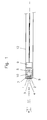
- the optical two-channel version of the 3D video endoscope according to Figure 1 is designed for gynecological use. It exists from the two pre-lenses 1 and 2, which represent the object.
- the optical axes 3 and 4 of the two at a distance of about 2.7 mm side-by-side lenses 1 and 2 are in one Level and intersect each other under the intended, for the decisive convergence or stereoscopic impression Squint angle a.
- the lenses 1, 2 have one in this embodiment Diameter of 2.7 mm, so that the optical input of the endoscope has a largest outer diameter of about 6.5 mm. Smaller diameters are sought to be used as Surgical or diagnostic endoscope for neurosurgery or To enable arthroscopy.
- the respective optical beam paths close immediately the two optical switches 7, 8 on in the respective optical axis 3 and 4 lie.
- these switches 7 and 8 electro-optical diaphragms which with a Frequency of 100 or 120 Hz complementary alternately transparent and can be controlled opaque.
- Frequency 100 or 120 Hz
- the beam deflection device 10 is arranged through which always forwarded only one field and with the only one Camera 9 of the endoscope is recorded.
- This camera 9 is one CCD camera (charge coupled device), d. H. with her everyone will be image entering the entrance area in picture elements (pixels) disassembled.
- CCD camera charge coupled device
- the further electronic Processing of the image signals thus obtained is e.g. B. in DE 38 08 969.
- the chip of such a CCD camera with the size of 6 - 4 mm 2 (1/3 "chip) has 400,000 gross pixels, of which at least 200,000 are used for image display according to today's video standards.
- the electrical signals at the output of the camera head 9 are via an electrical connection through the shaft 12 read out and put together on a monitor to image the scene.
- FIG. 2 shows the structure of the beam deflection 10 with a v or y-shaped prism 16.
- the two legs of the prism 16 are mirrored on their outer surface and through the middle of the Through the foot connected by optical cement. Both Beams of rays are passed through their respective Thighs reflected on the two thigh walls and kick then in the foot surface.
- Any offset of the two beam paths is too consider. This mistake is hardly significant because he compensated by "squinting" the observer on the screen can be.
- this offset completely eliminable.
- a construction variant based on conventional optical endoscope construction is that the purely optical part is distal End extends to the proximal area of the endoscope, d. H. the object is imaged using the two front lenses at the distal end, via the two optical switches on the Map the input of an image fiber bundle.
- the optoelectronic recording camera located on the handling area of the endoscope the optoelectronic recording camera that shows the fields at the optical fiber output.
- the optical Switches in the handling area would be two separate ones Optical fiber bundles from optical imaging to opto-electronic Camera needed.
Abstract
Description
Die Erfindung betrifft ein 3D-Video-Endoskop. Mit ihm kann der Anwender unter gewohnter dreidimensionaler Sicht in nicht unmittelbar zugänglichen Hohlräumen beobachten.The invention relates to a 3D video endoscope. With him you can Users with the usual three-dimensional view in not immediately observe accessible cavities.
In der DE 38 06 190 wird ein 3-D-Video-System mit kontinuierlicher, zweikanaliger Bildaufnahme und einer Bildwiedergabe über eine Polarisationseinrichtung beschrieben. Das 3D-Video-System hat in den beiden optischen Kanälen jeweils nur eine Strahlumlenkeinrichtung, somit sind optisch nur Spiegelbilder des Gegenstands erhältlich. Die Polarisationseinrichtung erlaubt darüber hinaus nicht, während der Betrachtung des Monitors den Kopf stärker aus der vorgesehenen Position zu schwenken.DE 38 06 190 describes a 3-D video system with continuous, two-channel image recording and image playback via described a polarization device. The 3D video system has only one beam deflecting device in each of the two optical channels, thus optically only mirror images of the object available. The polarization device allows above beyond, while looking at the monitor head to pivot more from the intended position.
Die DE 36 40 731 zeigt dagegen eine opto-elektronische 3D-Aufnahmeeinrichtung mit optischen Ventilen auch unmittelbar vor den Augen des Betrachters. Die optischen Achsen der Objektive bilden den Konvergenzwinkel oder Schielwinkel, der für das räumliche Sehen mit Tiefeneindruck wesentlich ist. Jeder Strahl wird zweimal über Spiegel oder Prismen umgelenkt, bis er auf den optischen Eingang der einen Video-Kamera trifft. Somit werden seitenrichtige Bilder wiedergegeben. In jedem der beiden Strahlengänge befindet sich ein optisches Ventil, so daß abwechselnd das rechte und linke Bild Durchlaß findet. Die Aufnahmekapazität der einen Video-Kamera steht für beide Bilder stets ausschließlich zur Verfügung.DE 36 40 731, on the other hand, shows an opto-electronic 3D recording device with optical valves also immediately before Eyes of the beholder. Form the optical axes of the lenses the convergence angle or squint angle, which is for the spatial Seeing with a deep impression is essential. Each ray is made twice redirected over mirrors or prisms until it hits the optical Entrance of a video camera. Thus, right-sided Images reproduced. In each of the two beam paths there is an optical valve, so that alternately right and left picture passes. The absorption capacity of the A video camera always stands for both pictures to disposal.
In der Druckschrift der Firma OPTIKON aus dem Jahr 1993 wird ein vollständiges und einsetzbares 3D-Video-System für die endoskopischen Chirurgie beschrieben, das im Prinzip genauso wie die oben erwähnte Literaturstelle mit zwei optischen Kanälen ausgestattet ist. Vor beiden Strahleintrittsflächen befindet sich je eine Vorlinse, die die davorliegende Umgebung abbilden. Beide optischen Kanäle führen auf je eine CCD-Kamera, die am proximalen Ende angeflanscht sind. Die Kamerasteuerungen sind mit einer 3D-Elektronik verbunden. Durch diese werden die Bilder der beiden Kameras mit einer Frequenz von 100 - 120 Hz im zeitlichen Wechsel auf einem Monitor dargestellt.In the 1993 OPTIKON publication, a complete and applicable 3D video system for endoscopic Surgery described, in principle, just like that equipped above with two optical channels is. There is one in front of each of the two beam entry areas a pre-lens that shows the surrounding area. Both optical channels lead to a CCD camera on the proximal one Are flanged at the end. The camera controls are with one 3D electronics connected. Through this the images of the both cameras with a frequency of 100 - 120 Hz in time Change shown on a monitor.
Der Aufbau des 3D-Video-Endoskops besteht im wesentlichen aus den zwei optischen Kanälen mit Vorsatzlinsen, die in einem Schaft untergebracht sind, und den auf diesen Schaft aufgesetzten beiden Kameras oder Kameraköpfen.The structure of the 3D video endoscope essentially consists of the two optical channels with auxiliary lenses, which are in one Shaft are housed, and the mounted on this shaft two cameras or camera heads.
In einer weiteren Literaturstelle, der US 4,924,853, wird ein 3D-Video-Endoskop beschrieben, das zwei Vorlinsen mit je einer optischen Achse aufweist. Im optischen Strahlengang nach den beiden Vorlinsen befinden sich steuerbare optische Schalter, die im gleichen Rhythmus komplementär abwechselnd transparent und opak gesteuert werden. Daran schließt sich eine Strahlumlenkeinrichtung an, die die optischen Achsen der beiden Strahlengänge auf der optische Achse einer optoelektronischen Kamera zusammenführt. Dadurch wird die Kamera an ihrem Ausgang im Rhythmus der beiden optischen Schalter einmal die elektrischen Signale des linken und dann die des rechten Bildes zur weiteren Video-Bearbeitung bereitstellen. Die Strahlumlenkeinrichtung besteht zunächst aus einem v-förmig prismatischen Strahlumlenkungsgruppe zur Strahlaufweitung und dann aus einer weiteren Strahlumlenkungsgruppe zur Zusammenführung beider Strahlachsen, die aus diskreten Prismen aufgebaut ist. Zwischen beiden Strahlumlenkungsgruppen befindet sich der jeweilige optische Schalter.In another reference, US 4,924,853, a 3D video endoscope described that two pre-lenses with one each has optical axis. In the optical beam path after the Both front lenses are controllable optical switches that in the same rhythm complementary alternating transparent and can be controlled opaque. This is followed by a beam deflection device the optical axes of the two beam paths merges on the optical axis of an optoelectronic camera. This causes the camera to exit at the rhythm of the two optical switches once the electrical signals of the left and then that of the right image for further video editing provide. The beam deflector initially exists from a V-shaped prismatic beam deflection group for beam expansion and then from another beam deflection group for merging both beam axes, which consist of discrete prisms. Between the two beam deflection groups the respective optical switch is located.
In der WO 87/01896 wird ebenfalls eine v-förmig prismatische Strahlführungsvorrichtung gezeigt und beschrieben, in der ein eintreffendes Lichtbündel in drei primäre Farbbündel aufgeteilt wird. Hier dient diese Vorrichtung nur zur Aufweitung der farbanteiligen optischen Achsen.WO 87/01896 also describes a V-shaped prismatic Beam guiding device shown and described in the incoming light bundle divided into three primary color bundles becomes. Here this device only serves to expand the color-based optical axes.
Der Erfindung liegt die Aufgabe zugrunde, ein 3D-Video-Endoskop bereitzustellen, das ohne Beeinträchtigung in der Bildqualität räumlich schlank gebaut werden kann und vor allem an der Stelle der opto-elektronischen Übergangs raumsparend aufgebaut ist, so daß enge Durchführungsbereiche passierbar bleiben.The invention has for its object a 3D video endoscope provide that without sacrificing image quality can be built spatially slim and above all on the spot the opto-electronic transition is designed to save space, so that narrow implementation areas remain passable.
Die Aufgabenstellung kommt vornehmlich aus dem Bereich der minimal invasiven Chirurgie, darüber hinaus aber ganz allgemein auch aus unterschiedlichen Bereichen der Hohlrauminspektion. Aus dem Bereich der Kanalinspektionssysteme kommt die Forderung, in unzugänglichen Rohrsystemen ein Inspektionssystem mit 3D-Aufnahmetechnik einsetzen zu können, mit dem eine wirklichkeitsgetreue, räumliche Darstellung der Szene möglich ist.The task mainly comes from the area of minimal invasive surgery, but more generally also from different areas of cavity inspection. Out the area of sewer inspection systems comes in inaccessible pipe systems an inspection system with 3D recording technology to be able to use, with a realistic, spatial representation of the scene is possible.
Diese Aufgabe wird erfindungsgemäß durch den Aufbau eines Endoskops gemäß dem Anspruch 1 gelöst. Paarweise treten dort nur noch die Vorlinsen und die beiden ansteuerbaren optischen Schalter im optischen Strahlengang auf.This object is achieved according to the invention by the construction of an endoscope solved according to claim 1. In pairs only occur there still the front lenses and the two controllable optical ones Switch in the optical beam path on.
Der Unteranspruch 2 kennzeichnet eine an sich bekannte Bauformen,
die je nach Einsatz vorteilhaft oder zweckmäßig ist, nämlich
die des mehr oder weniger abgeknickten Schafts.The
Das in Anspruch 1 gekennzeichnete 3D-Video-Endoskop hat nur noch einen Kamerakopf, an dessen Ausgang die elektrischen Signale zur Videoverarbeitung anstehen, d. h. im Schaft werden elektrische Signale über Kabel weitergeleitet. Damit entfällt ein optischer Übertragungskanal. Der Schaft kann steif, flexibel oder geknickt sein.The 3D video endoscope characterized in claim 1 only has a camera head, at whose output the electrical signals for Pending video processing, d. H. in the shaft are electrical Signals passed on via cable. This eliminates an optical Transmission channel. The shaft can be stiff, flexible or kinked his.
Hervorzuheben ist das Prinzp der Strahlumlenkung durch zweimalige Reflexion des reflektierten Strahls, wodurch ein seitenkonformes Bild aufrechterhalten wird.The principle of beam deflection by two should be emphasized Reflection of the reflected beam, creating a side conform Image is maintained.
Als optische Schalter haben sich elektro-optische Blenden (Anspruch 3) bewährt, die einfach und zuverlässig vom Kamerakopf aus gesteuert werden können. Dadurch besteht eine sichere Zuordnung zum linken oder rechten Bild (Video-Halbbild). Electro-optical diaphragms have become optical switches 3) proven that simple and reliable from the camera head can be controlled from. This ensures a secure assignment to the left or right picture (video field).
Das erfindungsgemäße Endoskop zeichnet sich durch Platzeinsparung und erheblich geringeren finanziellen Aufwand durch die Einsparung einer Kamera und die notwendige Signalaufbereitung (Sequentisierung der Teilbilder) gegenüber den bisher bekannten Bauweisen aus. Das Endoskop in der grundsätzlichen Bauweise nach Anspruch 1 zeichnet sich durch seine schlanke Bauweise aus, insbesondere im distalen Bereich, da dort keine sperrigen Baukomponenten vorhanden sind. Der einzige Kamerakopf, ein CCD-Chip, ist ein räumlich kleines Bauteil (Anspruch 4). Das Anflanschen des Endoskops an eine geeignete leistungsfähige 3D-Elektronik wird in bewährter Technik nach der Lehre aus der DE 38 08 969 durchgeführt.The endoscope according to the invention is characterized by space savings and significantly lower financial expenditure through the Saving a camera and the necessary signal processing (Sequencing of the partial images) compared to the previously known Construction methods. The basic design of the endoscope Claim 1 is characterized by its slim design, in particular in the distal area, since there are no bulky components available. The only camera head, a CCD chip, is a spatially small component (claim 4). The flanging of the endoscope to suitable, powerful 3D electronics is in proven technology according to the teaching of DE 38 08 969 carried out.
Sämtliche Komponenten des 3D-Endoskops in der einen oder anderen Bauweise sind vom Aufbau herkömmlicher 3D-Endoskope her bekannt und können bis auf den Einbau der beiden optischen Schalter, auch optische Ventile oder Shutter genannt, übernommen werden.All components of the 3D endoscope in one or the other Construction is known from the construction of conventional 3D endoscopes and except for the installation of the two optical switches, also called optical valves or shutters.
Im folgenden wird ein Ausführungsbeispiel des 3D-Video-Endoskops
näher beschrieben. Es zeigen:
Die optisch zweikanalige Ausführung des 3D-Video-Endoskops gemäß
Figur 1 ist für den gynäkologischen Einsatz konzipiert. Es besteht
aus den beiden Vorlinsen 1, und 2, die das Objekt abbilden.
Die optischen Achsen 3 und 4 der beiden im Abstand von etwa
2,7 mm nebeneinander liegenden Linsen 1 und 2 liegen in einer
Ebene und schneiden einander unter dem vorgesehenen, für den
stereoskopischen Eindruck maßgebenden Konvergenz- oder
Schielwinkel a. Die Linsen 1, 2 haben in dieser Ausführung einen
Durchmesser von 2,7 mm, so daß der optische Eingang des Endoskops
einen größten äußeren Durchmesser von etwa 6,5 mm aufweist.
Geringere Durchmesser werden angestrebt, um einen Einsatz als
Operations- oder Diagnose-Endoskop für die Neurochirurgie oder
Arthroskopie zu ermöglichen.The optical two-channel version of the 3D video endoscope according to
Figure 1 is designed for gynecological use. It exists
from the two pre-lenses 1 and 2, which represent the object.
The
Im jeweiligen optischen Strahlengang schließen sich unmittelbar
die beiden optischen Schalter 7, 8 an, die in der jeweiligen
optischen Achse 3 bzw. 4 liegen. Im Durchführungsbeispiel sind
diese Schalter 7 und 8 elektrooptische Blenden, die mit einer
Frequenz von 100 bzw. 120 Hz komplementär abwechselnd transparent
und opak gesteuert werden. Zur zuverlässigen und exakten
Zuordnung werden sie über den Kamerakopf 9 angesteuert, über den
die Bilder nacheinander ein- und ausgelesen werden.The respective optical beam paths close immediately
the two
Nach den beiden elektro-optischen Schaltern oder Blenden 7, 8
ist die Strahlumlenkeinrichtung 10 angeordnet, durch die hindurch
stets nur ein Halbbild weitergeleitet und mit der einzigen
Kamera 9 des Endoskops aufgenommen wird. Diese Kamera 9 ist eine
CCD-Kamera (charge coupled device),d. h. mit ihr wird jedes an
der Eintrittsfläche eintretende Bild in Bildelemente (pixel)
zerlegt. Für die zuverlässige Zuordnung der Halbbilder wird
zweckmäßigerweise die Steuerung der Blenden 7 und 8 direkt mit
dem Takt der CCD-Kamera 9 gesteuert. Die weitere elektronische
Verarbeitung der so gewonnenen Bildsignale ist z. B.in der DE 38
08 969 beschrieben.After the two electro-optical switches or
Der Chip einer solchen CCD-Kamera von der Größe von 6 - 4 mm2 (1/3"-Chip) hat 400 000 Bildpunkte brutto, von denen wenigstens 200 000 zur Bilddarstellung nach den heutigen Video-Standards ausgenutzt werden.The chip of such a CCD camera with the size of 6 - 4 mm 2 (1/3 "chip) has 400,000 gross pixels, of which at least 200,000 are used for image display according to today's video standards.
Beide Bauformen des 3D-Video-Endoskops mit den optischen Kanälen
6 nach Figur 1 und 2 liefern prinzipiell Bilder gleicher
Qualität, da der Aufnahmevcrgang durch die Kamera und die Shuttersteuerung
identisch ist. Im Schaft 12 können noch andere
Einrichtungen wie Beleuchtung und/oder Saug- und Spülkanal untergebracht
und mitgeführt werden, soweit die räumlichen Ver
hältnisse das zulassen und der Schaftaufbau dadurch nicht verkompliziert
wird und eine solche Kombination gefordert wird.Both designs of the 3D video endoscope with the optical channels
In principle, 6 according to FIGS. 1 and 2 provide images of the same
Quality because the recording process by the camera and the shutter control
is identical. Others can be in the
Die elektrischen Signale am Ausgang des Kamerakopfs 9 werden
über eine elektrische Verbindung durch den Schaft 12 hindurch
ausgelesen und auf einem Monitor zum Bild der Szene zusammengesetzt.The electrical signals at the output of the
Ob der Schaft 12 steif oder flexibel ausgeführt ist, entscheidet
sich am Einsatzfall. Der Vorteil der elektrischen Übertragung
durch den Schaft 12 hindurch liegt in der unproblematischen
elektrischen Signalübertragung. Der Schaft 12 ist mechanisch
robust und kann daher sorgloser behandelt werden. Der Biegeradius
des Schaftes kann sehr klein sein, ohne daß Bildpunkte
ausfallen, wie das etwa bei Bildleitfaserbündel bei zu kleinen
Biegeradien durch Bruch von einzelnen Fasern auftreten kann.
Eine mit einem vorgegebenen Winkel a abgeknickte Schaftausführung
ist somit einfach ohne besonderen konstruktiven Aufwand
herstellbar.Decides whether the
Figur 2 zeigt den Aufbau der Strahlumlenkung 10 mit einem v-
oder y-förmigen Prisma 16. Die beiden Schenkel des Prismas 16
sind an ihrer Mantelfläche verspiegelt und durch die Mitte des
Fußes hindurch miteinander durch optischen Kitt verbunden. Beide
Strahlenbündel werden beim Durchlauf durch ihren jeweiligen
Schenkel an den beiden Schenkelwänden reflektiert und treten
dann in der Fußfläche aus. Ein dabei durch die Reflektionsanordnung
auftretender Versatz der beiden Strahlengänge ist zu
berücksichtigen. Dieser Fehler fällt aber kaum ins Gewicht, weil
er durch "Nachschielen" des Beobachters am Bildschirm kompensiert
werden kann. Zum anderen ist durch Korrektur in der
Horizontalphase in der Kameraelektronik dieser Versatz vollständig
eliminierbar.FIG. 2 shows the structure of the
Eine vom herkömmlichen optischen Endoskopbau herrührende Bauvariante besteht darin, daß sich der rein optische Teil vom distalen Ende bis zum proximalen Bereich des Endoskops erstreckt, d. h. die Abbildung des Objekts erfolgt über die beiden Vorlinsen am distalen Ende, die über die beiden optischen Schalter auf den Eingang eines Bildleitfaserbündels abbilden. Am Ausgang des Bildleitfaserbündels, am Handhabungsbereich des Endoskops befindet sich die optoelektronische Aufnahmekamera, die die Halbbilder am Bildleitfaserausgang aufnimmt. Bei Verlegung der optischen Schalter in den Handhabungsbereich wären zwei getrennte Bildleitfaserbündel von der optischen Abbildung bis zur opto-elektronischen Kamera nötig. A construction variant based on conventional optical endoscope construction is that the purely optical part is distal End extends to the proximal area of the endoscope, d. H. the object is imaged using the two front lenses at the distal end, via the two optical switches on the Map the input of an image fiber bundle. At the exit of the Image fiber bundle, located on the handling area of the endoscope the optoelectronic recording camera that shows the fields at the optical fiber output. When laying the optical Switches in the handling area would be two separate ones Optical fiber bundles from optical imaging to opto-electronic Camera needed.
- 11
- VorlinsePre-lens
- 22nd
- VorlinsePre-lens
- 33rd
- optische Achseoptical axis
- 44th
- optische Achseoptical axis
- 55
- optische Achseoptical axis
- 66
- optischer Kanal, Stablinsensystem, Bildleitfaserbündeloptical channel, rod lens system, image fiber bundle
- 77
- Schalter, Blende, ShutterSwitch, aperture, shutter
- 88th
- Schalter, Blende, ShutterSwitch, aperture, shutter
- 99
- Kamerakopf, CCD-KameraCamera head, CCD camera
- 1010th
- StrahlumlenkeinrichtungBeam deflector
- 1111
- Prismaprism
- 1212th
- Schaft, EndoskopschaftShaft, endoscope shaft
- 1313
- 90°-Reflexionsprisma, Spiegel90 ° reflection prism, mirror
- 1414
- SpiegelprismaMirror prism
- 1515
- Kittputty
- 1616
- Prismaprism
- αα
- SchielwinkelSquint angle
Claims (4)
- 3D video endoscope for the observation of objects or surfaces in cavities, consisting of:and characterized bya) two preliminary lenses (1, 2) with an optical axis (3, 4) each;b) a controllable optical switch (7, 8) each, which is located in the downstream optical beam path, and which are controlled alternately and complementarily at the same rhythm of transparent and opaque mode;c) a beam deflection unit (10) located in the downstream optical beam path, which combines the optical axes (3, 4) of both beam paths on the optical axis (5) of an optoelectronic recording camera (9) with the light inlet area of the recording camera (9) lying on the common focal plane of the two preliminary lenses (1, 2) and the recording camera (9) supplying at the rhythm of both optical switches (7, 8) first the electric signals of the right and then of the left image for further video processing,i) the optical axes (3, 4) of the two preliminary lenses (1, 2) intersecting each other under an angle a,ii) the optical beam deflection unit (10) being a v- or y-shaped beam guiding system, where the optical axes (3, 4) enter the front surfaces of both legs, respectively, are reflected two times each on the mirror-coated walls of the system (10) and, after being combined, leave at the bottom of the deflection unit (10),iii) both optical switches which are operated complementarily (7, 8) being located upstream of the beam deflection unit (10).
- 3D video endoscope according to claim 1, characterized by the endoscope shaft axis (5) downstream of the optoelectronic image recording system (9) lying on the optical inlet axis of the recording camera (9) or under a given angle to it.
- 3D video endoscope according to claim 2, characterized by the optical switches (7, 8) being electro-optical screens.
- 3D video endoscope according to claim 3, characterized by the camera head (9) being a CCD chip.
Applications Claiming Priority (3)
| Application Number | Priority Date | Filing Date | Title |
|---|---|---|---|
| DE4424114A DE4424114C1 (en) | 1994-07-08 | 1994-07-08 | Three=dimensional video endoscope for medical use |
| DE4424114 | 1994-07-08 | ||
| PCT/EP1995/001922 WO1996002114A1 (en) | 1994-07-08 | 1995-05-19 | 3d video endoscope |
Publications (2)
| Publication Number | Publication Date |
|---|---|
| EP0770309A1 EP0770309A1 (en) | 1997-05-02 |
| EP0770309B1 true EP0770309B1 (en) | 2000-01-05 |
Family
ID=6522663
Family Applications (1)
| Application Number | Title | Priority Date | Filing Date |
|---|---|---|---|
| EP95920845A Expired - Lifetime EP0770309B1 (en) | 1994-07-08 | 1995-05-19 | 3d video endoscope |
Country Status (4)
| Country | Link |
|---|---|
| EP (1) | EP0770309B1 (en) |
| AT (1) | ATE188590T1 (en) |
| DE (2) | DE4424114C1 (en) |
| WO (1) | WO1996002114A1 (en) |
Families Citing this family (4)
| Publication number | Priority date | Publication date | Assignee | Title |
|---|---|---|---|---|
| JP3678162B2 (en) * | 2001-04-12 | 2005-08-03 | 株式会社島津製作所 | Radiation detector |
| DE10240826B3 (en) * | 2002-09-04 | 2004-05-06 | Albert-Ludwigs-Universität Freiburg | Method of operating an endoscope |
| DE102010050227A1 (en) | 2010-11-04 | 2012-05-10 | Siemens Aktiengesellschaft | Endoscope with 3D functionality |
| DE102010051882B4 (en) | 2010-11-22 | 2022-12-22 | Blazejewski Medi-Tech Gmbh | 3D video endoscope |
Family Cites Families (8)
| Publication number | Priority date | Publication date | Assignee | Title |
|---|---|---|---|---|
| JPS56158636A (en) * | 1980-05-09 | 1981-12-07 | Olympus Optical Co | Photographing apparatus |
| US4690526A (en) * | 1985-09-12 | 1987-09-01 | Hughes Aircraft Company | Prism assembly for a single light valve full-color projector |
| US4671613A (en) * | 1985-11-12 | 1987-06-09 | Gte Laboratories Inc. | Optical beam splitter prism |
| DE3640731A1 (en) * | 1986-11-28 | 1988-06-09 | Standard Elektrik Lorenz Ag | ARRANGEMENT FOR TRANSMITTING STEREOSCOPIC VIDEO IMAGES |
| US4873572A (en) * | 1987-02-27 | 1989-10-10 | Olympus Optical Co., Ltd. | Electronic endoscope apparatus |
| JPS63294509A (en) * | 1987-05-27 | 1988-12-01 | Olympus Optical Co Ltd | Stereoscopic endoscope device |
| DE3808969C1 (en) * | 1988-03-17 | 1989-10-19 | Kernforschungszentrum Karlsruhe Gmbh, 7500 Karlsruhe, De | Device for reproducing three-dimensional pictures |
| US4924853A (en) * | 1989-05-22 | 1990-05-15 | Medical Dimensions, Inc. | Stereoscopic medical viewing device |
-
1994
- 1994-07-08 DE DE4424114A patent/DE4424114C1/en not_active Expired - Fee Related
-
1995
- 1995-05-19 DE DE59507581T patent/DE59507581D1/en not_active Expired - Fee Related
- 1995-05-19 EP EP95920845A patent/EP0770309B1/en not_active Expired - Lifetime
- 1995-05-19 AT AT95920845T patent/ATE188590T1/en not_active IP Right Cessation
- 1995-05-19 WO PCT/EP1995/001922 patent/WO1996002114A1/en active IP Right Grant
Also Published As
| Publication number | Publication date |
|---|---|
| EP0770309A1 (en) | 1997-05-02 |
| WO1996002114A1 (en) | 1996-01-25 |
| ATE188590T1 (en) | 2000-01-15 |
| DE59507581D1 (en) | 2000-02-10 |
| DE4424114C1 (en) | 1995-06-01 |
Similar Documents
| Publication | Publication Date | Title |
|---|---|---|
| DE19814731B4 (en) | surgical microscope | |
| DE3818104C2 (en) | ||
| DE10027166B4 (en) | stereoscopic microscope | |
| EP0753164B1 (en) | Stereomicroscope | |
| DE3806190C2 (en) | ||
| DE19509885A1 (en) | Stereo endoscope for microsurgery | |
| DE69834234T2 (en) | Composite display device | |
| WO2002099506A2 (en) | Device and method for the laser projection of high-resolution images onto the retina of the eye, superimposed with the image content of the field of vision | |
| DE4212924A1 (en) | Surgical operation stereo microscope - has several optical imaging systems to enable object to be simultaneously observed by numerous viewers and photographed | |
| DE102010022430A1 (en) | Field of view device for an endoscope | |
| DE60031348T2 (en) | Image observation device and image observation system | |
| EP0770309B1 (en) | 3d video endoscope | |
| DE19532400B4 (en) | Stereo endoscope with angled viewing direction | |
| DE10021063A1 (en) | Stereo microscope enables additional image to be made visible with blocked section of optical image, whereby area of blocked section can be varied; beams are polarised, superimposed | |
| DE4225507C2 (en) | Stereoscopic endoscope | |
| DE4301466C1 (en) | Optical system for stereoscopic endoscope - comprises main lens, connecting optic, transmission optic and endoscope lens, transmission optics being constructed from identical and symmetrical kit components | |
| DE19542827A1 (en) | Stereoscopic imaging system for surgical microscope | |
| EP0582148B1 (en) | Endoscopic attachment for stereoscopic viewing system | |
| DE3437879A1 (en) | STEREOSCOPIC OPTICAL DEVICE | |
| DE20022631U1 (en) | Beam splitter module for microscopes | |
| DE19549456B4 (en) | Stereo endoscope for microsurgery - has images provided by pair of objective lens systems fed to proximal end of endoscope by common transmission lens system | |
| DE3943712C2 (en) | Endoscope with a video camera | |
| DE3928421A1 (en) | Endoscope with miniature TV camera | |
| DE10240826B3 (en) | Method of operating an endoscope | |
| DE102019130950B3 (en) | Boroscope with pattern projection |
Legal Events
| Date | Code | Title | Description |
|---|---|---|---|
| PUAI | Public reference made under article 153(3) epc to a published international application that has entered the european phase |
Free format text: ORIGINAL CODE: 0009012 |
|
| 17P | Request for examination filed |
Effective date: 19961128 |
|
| AK | Designated contracting states |
Kind code of ref document: A1 Designated state(s): AT CH DE FR GB LI |
|
| 17Q | First examination report despatched |
Effective date: 19980330 |
|
| GRAG | Despatch of communication of intention to grant |
Free format text: ORIGINAL CODE: EPIDOS AGRA |
|
| GRAG | Despatch of communication of intention to grant |
Free format text: ORIGINAL CODE: EPIDOS AGRA |
|
| GRAH | Despatch of communication of intention to grant a patent |
Free format text: ORIGINAL CODE: EPIDOS IGRA |
|
| GRAH | Despatch of communication of intention to grant a patent |
Free format text: ORIGINAL CODE: EPIDOS IGRA |
|
| GRAA | (expected) grant |
Free format text: ORIGINAL CODE: 0009210 |
|
| AK | Designated contracting states |
Kind code of ref document: B1 Designated state(s): AT CH DE FR GB LI |
|
| PG25 | Lapsed in a contracting state [announced via postgrant information from national office to epo] |
Ref country code: GB Free format text: LAPSE BECAUSE OF FAILURE TO SUBMIT A TRANSLATION OF THE DESCRIPTION OR TO PAY THE FEE WITHIN THE PRESCRIBED TIME-LIMIT Effective date: 20000105 Ref country code: FR Free format text: LAPSE BECAUSE OF FAILURE TO SUBMIT A TRANSLATION OF THE DESCRIPTION OR TO PAY THE FEE WITHIN THE PRESCRIBED TIME-LIMIT Effective date: 20000105 |
|
| REF | Corresponds to: |
Ref document number: 188590 Country of ref document: AT Date of ref document: 20000115 Kind code of ref document: T |
|
| REG | Reference to a national code |
Ref country code: CH Ref legal event code: NV Representative=s name: ROTTMANN, ZIMMERMANN + PARTNER AG Ref country code: CH Ref legal event code: EP |
|
| REF | Corresponds to: |
Ref document number: 59507581 Country of ref document: DE Date of ref document: 20000210 |
|
| EN | Fr: translation not filed | ||
| GBV | Gb: ep patent (uk) treated as always having been void in accordance with gb section 77(7)/1977 [no translation filed] |
Effective date: 20000105 |
|
| PLBE | No opposition filed within time limit |
Free format text: ORIGINAL CODE: 0009261 |
|
| STAA | Information on the status of an ep patent application or granted ep patent |
Free format text: STATUS: NO OPPOSITION FILED WITHIN TIME LIMIT |
|
| 26N | No opposition filed | ||
| PGFP | Annual fee paid to national office [announced via postgrant information from national office to epo] |
Ref country code: CH Payment date: 20010430 Year of fee payment: 7 |
|
| PGFP | Annual fee paid to national office [announced via postgrant information from national office to epo] |
Ref country code: AT Payment date: 20010525 Year of fee payment: 7 |
|
| PG25 | Lapsed in a contracting state [announced via postgrant information from national office to epo] |
Ref country code: AT Free format text: LAPSE BECAUSE OF NON-PAYMENT OF DUE FEES Effective date: 20020519 |
|
| PG25 | Lapsed in a contracting state [announced via postgrant information from national office to epo] |
Ref country code: LI Free format text: LAPSE BECAUSE OF NON-PAYMENT OF DUE FEES Effective date: 20020531 Ref country code: CH Free format text: LAPSE BECAUSE OF NON-PAYMENT OF DUE FEES Effective date: 20020531 |
|
| REG | Reference to a national code |
Ref country code: CH Ref legal event code: PL |
|
| PGFP | Annual fee paid to national office [announced via postgrant information from national office to epo] |
Ref country code: DE Payment date: 20030424 Year of fee payment: 9 |
|
| PG25 | Lapsed in a contracting state [announced via postgrant information from national office to epo] |
Ref country code: DE Free format text: LAPSE BECAUSE OF NON-PAYMENT OF DUE FEES Effective date: 20041201 |