EP0770032B1 - Abspulvorrichtung - Google Patents
Abspulvorrichtung Download PDFInfo
- Publication number
- EP0770032B1 EP0770032B1 EP95924633A EP95924633A EP0770032B1 EP 0770032 B1 EP0770032 B1 EP 0770032B1 EP 95924633 A EP95924633 A EP 95924633A EP 95924633 A EP95924633 A EP 95924633A EP 0770032 B1 EP0770032 B1 EP 0770032B1
- Authority
- EP
- European Patent Office
- Prior art keywords
- cable
- reeling device
- reel
- main reel
- hub
- Prior art date
- Legal status (The legal status is an assumption and is not a legal conclusion. Google has not performed a legal analysis and makes no representation as to the accuracy of the status listed.)
- Expired - Lifetime
Links
Images


Classifications
-
- B—PERFORMING OPERATIONS; TRANSPORTING
- B65—CONVEYING; PACKING; STORING; HANDLING THIN OR FILAMENTARY MATERIAL
- B65H—HANDLING THIN OR FILAMENTARY MATERIAL, e.g. SHEETS, WEBS, CABLES
- B65H75/00—Storing webs, tapes, or filamentary material, e.g. on reels
- B65H75/02—Cores, formers, supports, or holders for coiled, wound, or folded material, e.g. reels, spindles, bobbins, cop tubes, cans, mandrels or chucks
- B65H75/34—Cores, formers, supports, or holders for coiled, wound, or folded material, e.g. reels, spindles, bobbins, cop tubes, cans, mandrels or chucks specially adapted or mounted for storing and repeatedly paying-out and re-storing lengths of material provided for particular purposes, e.g. anchored hoses, power cables
- B65H75/38—Cores, formers, supports, or holders for coiled, wound, or folded material, e.g. reels, spindles, bobbins, cop tubes, cans, mandrels or chucks specially adapted or mounted for storing and repeatedly paying-out and re-storing lengths of material provided for particular purposes, e.g. anchored hoses, power cables involving the use of a core or former internal to, and supporting, a stored package of material
- B65H75/44—Constructional details
- B65H75/4418—Arrangements for stopping winding or unwinding; Arrangements for releasing the stop means
- B65H75/4428—Arrangements for stopping winding or unwinding; Arrangements for releasing the stop means acting on the reel or on a reel blocking mechanism
-
- B—PERFORMING OPERATIONS; TRANSPORTING
- B65—CONVEYING; PACKING; STORING; HANDLING THIN OR FILAMENTARY MATERIAL
- B65H—HANDLING THIN OR FILAMENTARY MATERIAL, e.g. SHEETS, WEBS, CABLES
- B65H75/00—Storing webs, tapes, or filamentary material, e.g. on reels
- B65H75/02—Cores, formers, supports, or holders for coiled, wound, or folded material, e.g. reels, spindles, bobbins, cop tubes, cans, mandrels or chucks
- B65H75/34—Cores, formers, supports, or holders for coiled, wound, or folded material, e.g. reels, spindles, bobbins, cop tubes, cans, mandrels or chucks specially adapted or mounted for storing and repeatedly paying-out and re-storing lengths of material provided for particular purposes, e.g. anchored hoses, power cables
- B65H75/38—Cores, formers, supports, or holders for coiled, wound, or folded material, e.g. reels, spindles, bobbins, cop tubes, cans, mandrels or chucks specially adapted or mounted for storing and repeatedly paying-out and re-storing lengths of material provided for particular purposes, e.g. anchored hoses, power cables involving the use of a core or former internal to, and supporting, a stored package of material
- B65H75/44—Constructional details
- B65H75/4449—Arrangements or adaptations to avoid movable contacts or rotary couplings, e.g. by the use of an expansion chamber for a lenght of the cord or hose
-
- B—PERFORMING OPERATIONS; TRANSPORTING
- B65—CONVEYING; PACKING; STORING; HANDLING THIN OR FILAMENTARY MATERIAL
- B65H—HANDLING THIN OR FILAMENTARY MATERIAL, e.g. SHEETS, WEBS, CABLES
- B65H75/00—Storing webs, tapes, or filamentary material, e.g. on reels
- B65H75/02—Cores, formers, supports, or holders for coiled, wound, or folded material, e.g. reels, spindles, bobbins, cop tubes, cans, mandrels or chucks
- B65H75/34—Cores, formers, supports, or holders for coiled, wound, or folded material, e.g. reels, spindles, bobbins, cop tubes, cans, mandrels or chucks specially adapted or mounted for storing and repeatedly paying-out and re-storing lengths of material provided for particular purposes, e.g. anchored hoses, power cables
- B65H75/38—Cores, formers, supports, or holders for coiled, wound, or folded material, e.g. reels, spindles, bobbins, cop tubes, cans, mandrels or chucks specially adapted or mounted for storing and repeatedly paying-out and re-storing lengths of material provided for particular purposes, e.g. anchored hoses, power cables involving the use of a core or former internal to, and supporting, a stored package of material
- B65H75/44—Constructional details
- B65H75/4457—Arrangements of the frame or housing
- B65H75/4471—Housing enclosing the reel
-
- B—PERFORMING OPERATIONS; TRANSPORTING
- B65—CONVEYING; PACKING; STORING; HANDLING THIN OR FILAMENTARY MATERIAL
- B65H—HANDLING THIN OR FILAMENTARY MATERIAL, e.g. SHEETS, WEBS, CABLES
- B65H2551/00—Means for control to be used by operator; User interfaces
- B65H2551/10—Command input means
- B65H2551/13—Remote control devices, e.g. speech recognition
Definitions
- the present invention pertains to the art of reeling devices and, more particularly, to a compact reeling device for the controlled coiling and uncoiling of a cable from within a housing wherein one end of the cable is fixed to the housing and the other end can be pulled to deploy a desired length of cable.
- a reeling device is disclosed in DE 3128545A .
- Such a reeling device includes a hub having one end of the cable located at the center of the hub and the remainder of the cable being wound in successive radial layers.
- a reeling device if one end portion of the cable is fixed relative to the remainder of the cable in order to provide a stationary electrical connection location, some provision must be made to prevent the stationary portion of the cable from twisting, kinking and ultimately failing as the reel is rotated during winding and unwinding of the cable.
- slip rings are employed to provide an electrical connection between the stationary and rotatable portions of the cable.
- slip rings can be the source of undesirable electrical noise and intermittent electrical contact.
- the present invention provides a reeling device including a single length of cable wound upon main and secondary reels that are rotatably mounted within a housing to which one end of the cable is fixed wherein the amount of cable provided on the secondary reel is minimized.
- a reeling device including a single length of cable wound upon main and secondary reels that are rotatably mounted within a housing to which one end of the cable is fixed wherein the amount of cable provided on the secondary reel is minimized.
- the main and secondary reels include a common hub member that is formed with a hole extending therethrough from the main reel to the secondary reel.
- a single length of cable is wound upon the two reels with a first end portion of the cable being coiled upon the main reel, an intermediate portion thereof extending through the hole formed in the common hub member and a second end portion of the cable being coiled about the secondary reel.
- the second end portion of the cable is substantially shorter than the first end portion and includes an end that is fixed to the housing.
- the reeling device further includes a drive system for controlling the winding and unwinding of the cable upon the reels.
- the drive system includes a servomotor that is drivingly connected to the common hub member and responsive to tension placed on the cable.
- the drive system provides for controlled deployment of the cable by providing a resistive torque to the deployment of the cable when excessive force is applied to withdraw the cable from the housing and controlled retraction by establishing a safe re-coil rate.
- the drive system is also responsive to signals received from optical sensors, positioned adjacent to the main reel, for indicating fully wound and fully unwound states of the cable respectively. The sensors are fixed to the housing and function to sense the absence or presence of the cable at specified radial distances from the hub of the main reel through a transparent flange portion of the main reel.
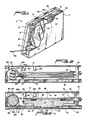
- Reeling device 2 includes a housing 5 consisting of a first side wall 8, an opposing side wall 10 and various peripheral side walls which are not depicted in the drawings. Housing 5 is divided by a partition member 14, attached to first side wall 8 through a plurality of circumferentially spaced cross braces 16, into first and second chambers 18 and 20. Partition member 14 includes a central aperture 23 which opens first chamber 18 into second chamber 20.
- Reeling device 2 also includes a hub member 27 that is formed with a central flange 30.
- Hub member 27 includes a main hub portion 36 formed at a first side 37 of central flange 30 and a secondary hub portion 39 projecting from an auxiliary flange portion 41 of central flange 30.
- Hub member 27 is rotatably mounted within housing 5 by means of a connector portion 43 of a bearing unit (not shown) that is positioned within and defines a centrally located rotational axis for hub member 27. As shown, connector portion 43 engages side wall 10 of housing 5 in order to support hub member 27 with a friction reducing washer 46 therebetween.
- Hub member 27 is provided with a through hole 49 that extends between main hub portion 36 and secondary hub portion 39 and is radially spaced from the central rotational axis of hub member 27.
- Reeling device 2 defines a main reel generally indicated at 51.
- Main reel 51 is defined by main hub portion 36, central flange 30 and another flange member 53 that is secured for rotation to main hub portion 36 by any means known in the art.
- flange member 53 is preferably formed from a transparent material such as plexiglass.
- a single length cable 60 includes a first, main portion 63 that is coiled around main hub portion 36 between central flange 30 and transparent flange member 53, an intermediate section (not shown) that extends within through hole 49 and a second portion 69 that is coiled about secondary hub portion 39.
- central flange 30 and transparent flange member 53 are preferably spaced a distance only slightly greater than the width of cable 60.
- first portion 63 of cable 60 is coiled in successive radial layers.
- first portion 63 extends about a guide pulley 74 and out of housing 5.
- Guide pulley 74 is rotatably mounted upon a shaft 75 that is fixed to both first side wall 8 and partition member 14.
- Second portion 69 of cable 60 includes an end section 77 that is shown in Figures 4-6 to project through an aperture 78 formed in housing 5. Although not shown in the drawings, it is to be understood that end section 77 is fixed to housing 5, either at or adjacent to aperture 78, such that the length of cable 60 within second chamber 20 is finite and remains constant.
- the particular length of second portion 69 is chosen based on the relative diameters between main and secondary hub portions 36, 39 and the desired pay-out or deployment length of first portion 63. Therefore, a substantial length of cable 60 can extend through aperture 78 for attaching cable 60 to an electrical unit or cable 60 could terminate in an electrical connector at aperture 78.
- secondary hub portion 39 is formed with a generally V-shaped slot 80 that leads to through hole 49.
- V-shaped slot 80 is provided with curved edges 82 and 83 which enables second portion 69 to be smoothly coiled about secondary hub member 39 in either direction.
- second portion 69 of cable 60 can be considered a loop of cable that is held captive within a bin defined by second chamber 20.
- This bin configuration therefore provides the transition between deployable first portion 63 and a stationary output.
- the reeling device 2 is designed to handle this loop without jamming during operation thereof while maintaining this loop of cable isolated from forces exerted on first portion 63 as discussed more fully below.
- central flange 30 is provided with an annular recess 88 (see Figures 2 and 3 ) that receives a drive belt 91 forming part of a drive system.
- Drive belt 91 is depicted as a round varathane belt although various round and/or flat belts could be utilized.
- Drive belt 91 further extends about an output pulley 93 of a drive motor 94.
- drive motor 94 constitutes a servomotor that can be driven in a uni-directional manner but which can be rotated in an opposite direction in an overrunning manner.
- Servomotor 94 receives drive power through a portable DC power source provided within housing 5 for controlling the winding and unwinding of cable 60 as discussed more fully below.
- Servomotor 94 is secured to housing 5 by means of two brackets 97 and 98.
- Drive belt 91 further extends around a transition pulley 103 (see Figures 1 and 2 ) that alters the orientation of drive belt 91.
- Transition pulley 103 is rotatably mounted to bracket 97 by means of a bolt 105.
- Servomotor 94 is also responsive to signals from optical activation/de-activation sensors 108 and 109, preferably infrared sensors. As shown, sensors 108, 109 are secured to an inner surface 112 of first side wall 8 and sense the presence or absence of cable 60 from a predetermined portion of main hub portion 36. More specifically, sensor 108 is positioned directly adjacent the outer radial end of main hub portion 36. Sensor 108 emits a light beam that will be reflected back to sensor 108 by radial surface portion 116 of central flange 30 if cable 60 is not present. For this purpose, radial surface portion 116 preferably evinces a highly polished surface or is coated with a metallic, highly reflective coating.
- sensor 108 receives a reflected signal, this indicates that first portion 63 of cable 60 is fully deployed or unwound and a signal is sent, through suitable circuitry as discussed more fully below with reference to Figure 8 , to servomotor 94 in order to prevent further unwinding.
- drive motor 95 is automatically operated to retract cable 60 a predetermined amount necessary to ensure that some cable remains on main reel 51 in order to permit tension commands to be sensed as further discussed below.
- Sensor 109 operates in a similar fashion to prevent overwinding of cable 60.
- reeling device 2 operates in today's marketplace such as those sold by the Canon Corporation, as well as the generator unit which provides motion sensing to the system.
- drive motor 95 is responsive to forces exerted on first portion 63 of cable 60 by an operator of reeling device 2. If first portion 63 is withdrawn at a rate such that a permissible tension level is maintained on cable 60 and hub member 27 does not overrun which could cause undesirable slack in first portion 63 of first reel 51, servomotor 94 will remain deactivated and will be permitted to rotate in a direction opposite to its rotational drive direction.
- servomotor 94 The interconnection of servomotor 94 to hub member 27 will provide a feedback tension on cable 60. However, when a predetermined threshold force on first portion 63 is exceeded as sensed by the generator unit, servomotor 94 will begin to rotate in a direction opposite to the deployment direction of cable 60 from main hub portion 36 so as to provide an increased resistance that can be felt by the user. When first portion 63 of cable 60 is deployed the desired length and held momentarily to allow the system to sense the cessation of pull, servomotor 94 is deactivated. With this arrangement, the user can stop the deployment of cable 60 at any desired position.
- reeling device 2 is insensitive to small or inadvertent pulls on cable 60, while responding reliably to intentional cable pull commands.
- the sensitivity of the system, as well as the cable retraction speed can be set based on system parameters and user preferences. For example, in a preferred embodiment, the retraction speed is set to 16,4 cm (six inches) of cable per second.
- Figure 8 schematically illustrates the circuit arrangement used to control the operation of servomotor 94. If reeling device 2 is idle, switch S1, preferably comprised of transistors, will be closed which will function to interrupt the supply of power from the power source to servomotor 94. In addition, since hub member 27 is stationary, the generator will not be rotated. When cable 60 is pulled upon to deploy first portion 63, the generator will be rotated with the rotation of hub member 27. If first portion 63 is withdrawn from housing 5 at a permissible rate, the system will remain in its present state.
- switch S1 preferably comprised of transistors
- first portion 63 is withdown with greater force, the generator will produce a positive voltage signal which will cause switch S1 to open, thereby causing servomotor 94 be activated in order to provide a resistive force to the deployment of cable 60.
- the voltage generated will also control a speed regulator SR to reduce to power actually supplied to servomotor 94 by the power source such that servomotor 94 operates at a first, low level in order to provide the desired holdback torque that can be sensed by the user.
- Infrared sensors 108 and 109 are provided in the circuit between the power source and servomotor 94. These sensors function in the manner described above by interrupting the power to servomotor 94 depending on the amount of cable 60 deployed. For example, if first portion 63 reaches its near fully deployed length, sensor 108 would close a bypass loop to servomotor 94 to prevent further power thereto. These bypass arrangements could be timed such that servomotor 94 will be cut-off a predetermined time following the closing of the bypass loop.
- first portion 63 of cable 60 When first portion 63 of cable 60 is abruptly pulled and then released so as to cause retraction of cable 60, the generator will generate a negative voltage, again open switch S1 and set the speed regulator SR to a higher permissible operation voltage for servomotor 94 in order to provide for sufficient power for retraction.
- a remote control unit for switch S1 could also be employed as illustrated in order to provide a desired supply of power to servomotor 94.
- a plurality of diodes are placed across the windings of servomotor 94 to provide dynamic braking should first portion 63 be pulled when no power is applied to the reeling device 2. This prevents unwanted flywheeling of hub member 27 which could result in cable 60 becoming jammed within housing 5.
- first portion 63 When first portion 63 is fully wound upon main hub portion 36, second portion 69 of cable 60 will also be in a first, fully wound state in one rotational direction about secondary hub portion 39 as illustrated in Figure 4 .
- second portion 69 When fully wound, second portion 69 is preferably provided with a little slack in order to assure non-binding of the device.
- main hub portion 36 As main hub portion 36 is rotated by tension applied to first portion 63 of cable 60, secondary hub portion 39 will be simultaneously rotated in the same rotational direction.
- first portion 63 is approximately half deployed, second portion 69 will be fully unwound from secondary hub portion 39 as illustrated in Figure 5 . In this second sate, cable 60 within second chamber 20 will be free to loop and freely fall into the bin defined by second chamber 20.
- first portion 63 continues to be deployed, second portion 69 will be rewound in an opposite direction onto secondary hub portion 39 as main hub portion 36 continues to rotate in the same direction.
- reeling device 2 When first portion 63 is fully deployed, reeling device 2 will assume a third state as shown in Figure 6 wherein second portion 69 of cable 60 is again fully wound upon secondary hub portion 39.
- the ability of second portion 69 to assume these three states within the bin defined by second chamber 20 results in a reduced cable length as compared to known prior art arrangements. This reduction in bin loading is very significant in avoiding jamming of the untensioned cable loop in the bin.
- servomotor 94 will automatically re-wind cable 60. As stated above, during retraction of first portion 63 of cable 60, servomotor 94 will maintain a requisite operational rate which will prevent any potentially dangerous coiling sequences from occurring.
- second portion 69 of cable 60 is fully unwound from and then rewound onto secondary hub portion 39 within second chamber 20 as first portion 63 is fully unwound from main hub portion 36.
- the same sequence of events occurs upon rewinding of first portion 63 as well.
- the length of second portion 69 can be greatly reduced as compared to known prior art arrangements.
- a 3:1 ratio is obtained between the length of first portion 63 of cable 60 and second portion 69 which minimizes the required length of second portion 69 for a given length of first portion 63 as compared to the prior art.
- second chamber 20 is defined in part by fixed side wall 10 and also fixed partition member 14.
- auxiliary flange portion 41 of central flange rotates with second hub portion 39.
- auxiliary flange portion 41 is sized to extend radially from second hub portion 39 a distance at least equal to that of second portion 69 of cable 60 when second portion 69 is fully wound in order to reduce any binding.
- outer surface 50 of auxiliary flange portion 41 is spaced from side wall 10 a distance greater than the width of cable 60 but less than twice the width. This precludes the development of packing forces that could result in progressive tightening and binding of the device if two fixed flanges were used. It is also possible to apply a low friction material, such as TEFLON to inner side 125 of side wall 10 as indicated at 12 in Figure 3 .
Landscapes
- Storing, Repeated Paying-Out, And Re-Storing Of Elongated Articles (AREA)
- Storage Of Web-Like Or Filamentary Materials (AREA)
Claims (13)
- Abspulvorrichtung, umfassend:ein Gehäuse (5);eine Hauptspule (51), die im genannten Gehäuse zum Rotieren um eine Drehachse montiert ist, wobei die genannte Hauptspule einen Nabenabschnitt (36) und wenigstens einen Flanschabschnitt (30) aufweist, der am genannten Nabenabschnitt zum Rotieren durch denselben befestigt ist, wobei der genannte Nabenabschnitt einen zugeordneten Durchmesser aufweist;eine Nebenspule, die an der genannten Hauptspule zum Rotieren durch dieselbe befestigt ist, wobei die genannte Nebenspule einen Nabenabschnitt (39) aufweist, der sich innerhalb des genannten Gehäuses (5) erstreckt und wenigstens einen Flanschabschnitt (41) aufweist, der mit dem Nabenabschnitt der genannten Nebenspule drehbar ist undein Kabel (60), das einen ersten Abschnitt (63) einer vorher festgelegten Länge aufweist, der um den Nabenabschnitt (36) der genannten Hauptspule (51) gewickelt ist und einen zweiten Abschnitt (69) einer vorher festgelegten Länge aufweist, die geringer als die vorher festgelegte Länge des genannten ersten Abschnitts (63) ist, die um den Nabenabschnitt der genannten Nebenspule gewickelt ist, wobei der genannte erste Abschnitt (63) an einem Endabschnitt des genannten Kabels abschließt, das derart angepasst ist, um durch einen Bediener der genannten Abspulvorrichtung zum Einsatz einer gewünschten Länge des ersten Abschnitts des genannten Kabels gezogen zu werden und der genannte zweite Abschnitt (69) an einem anderen Endabschnitt (77) des genannten Kabels abschließt, das fest mit dem genannten Gehäuse (5) verbunden ist;wobei während der erste Abschnitt (63) des genannten Kabels vollständig von der genannten Hauptspule (51) abgewickelt wird, der zweite Abschnitt (69) des genannten Kabels gleichzeitig vollständig von der genannten Nebenspule abgewickelt und danach wieder aufgewickelt wird,
dadurch gekennzeichnet, dass diese ein Unterteilungsglied (14) umfasst, das das genannte Gehäuse in erste und zweite Kammern (18, 20) unterteilt, wobei die Hauptspule (51) innerhalb der ersten Kammer montiert ist und sich die Nebenspule innerhalb der zweiten Kammer (20) erstreckt und dass die genannte zweite Kammer zwischen dem genannten Unterteilungsglied (14) und einer Außenwand (10) des genannten Gehäuses definiert ist, wobei die zweite Kammer (20) eine zugeordnete Breite aufweist, die etwas größer ist, als die Breite des genannten Kabels und sich über den äußeren Umfang des genannten Flansches (41) der genannten Nebenspule hinaus erstreckt. - Abspulvorrichtung nach Anspruch 1, weiter umfassend ein zentrales Nabenglied (27), das erste und zweite gegenüberliegende Seiten aufweist, wobei der Nabenabschnitt (36) der genannten Hauptspule an der ersten Seite des genannten zentralen Nabenglieds befestigt ist und der Nabenabschnitt (39) der genannten Nebenspule an der zweiten Seite des genannten zentralen Nabenglieds befestigt ist, wobei das zentrale Nabenglied (27) eine Öffnung (40) aufweist, die sich zwischen den ersten und zweiten Seiten erstreckt, durch welche sich das genannte Kabel erstreckt.
- Abspulvorrichtung nach Anspruch 1 oder 2, wobei der Nabenabschnitt der genannten Nebenspule einen zugeordneten Durchmesser aufweist, der geringer ist, als der Durchmesser, der dem Nabenabschnitt der genannten Hauptspule zugeordnet ist.
- Abspulvorrichtung nach Anspruch 3, wobei die genannten Haupt- und Nebenspulen angeformt sind.
- Abspulvorrichtung nach einem der Ansprüche 1 bis 4, wobei das genannte zentrale Nabenglied (27) weiter einen zentralen Flansch (30) aufweist, der wenigstens teilweise wenigstens einen Flanschabschnitt der genannten Hauptspule (51) definiert.
- Abspulvorrichtung nach Anspruch 5, weiter umfassend Mittel (94) zum Antrieb der genannten Hauptspule (50) zum Rotieren um die genannte Drehachse, wobei das genannte Antriebsmittel innerhalb des genannten Gehäuses (5) montiert ist und in einer Antriebsverbindung an die genannte Hauptspule gekoppelt ist.
- Abspulvorrichtung nach Anspruch 6, wobei das genannte Antriebsmittel (94) einen Motor umfasst, der ein Antriebsglied und Mittel zur Antriebsverbindung des genannten Antriebsglieds mit dem genannten zentralen Flansch aufweist.
- Abspulvorrichtung nach Anspruch 7, wobei das genannte Mittel zur Antriebsverbindung des genannten Antriebsglieds mit dem genannten zentralen Flansch ein Endlosband (91) aufweist, das sich um den genannten zentralen Flansch des genannten Antriebsglieds erstreckt.
- Abspulvorrichtung nach einem der Ansprüche 1 bis 8, weiter umfassend Mittel (94) zum Antrieb der genannten Hauptspule (51) zum Rotieren um die genannte Drehachse, wobei das genannte Antriebsmittel innerhalb des genannten Gehäuses (5) montiert und zur Antriebsverbindung an die genannte Hauptspule gekoppelt ist.
- Abspulvorrichtung nach Anspruch 9, weiter umfassend Mittel zum Aktivieren und Deaktivieren des genannten Antriebsmittels, um das Rotieren der genannten Hauptspule basierend auf erfassten Betriebsparametern der genannten Abspulvorrichtung zu steuern.
- Abspulvorrichtung nach Anspruch 10, weiter umfassend ein transparentes Flanschglied (53), das an der genannten Hauptspule (51) befestigt ist, wobei das genannte Mittel zum Aktivieren und Deaktivieren erste und zweite Sensoren (108, 109) aufweist, die durch das genannte Gehäuse (51) neben dem genannten transparenten Flanschglied (53) getragen sind, wobei die genannten Sensoren Signale bezüglich der Menge an auf der genannten Hauptspule gewickeltem Kabel bereitstellen.
- Abspulvorrichtung nach Anspruch 11, wobei das genannte Kabel eine zugeordnete Breite aufweist und der genannte wenigstens eine Flanschabschnitt und das genannte transparente Flanschglied durch einen Abstand beabstandet sind, der geringfügig größer ist, als die Breite des genannten Kabels.
- Abspulvorrichtung nach einem der Ansprüche 1 bis 12, wobei die genannte Außenwand (48) der zweiten Kammer (20) eine Innenfläche (125) aufweist, die mit einem Material mit niedriger Reibung (128) ausgekleidet ist.
Applications Claiming Priority (3)
| Application Number | Priority Date | Filing Date | Title |
|---|---|---|---|
| US266590 | 1994-06-28 | ||
| US08/266,590 US5526997A (en) | 1994-06-28 | 1994-06-28 | Reeling device |
| PCT/US1995/007864 WO1996000693A1 (en) | 1994-06-28 | 1995-06-28 | Reeling device |
Publications (3)
| Publication Number | Publication Date |
|---|---|
| EP0770032A1 EP0770032A1 (de) | 1997-05-02 |
| EP0770032A4 EP0770032A4 (de) | 1998-01-21 |
| EP0770032B1 true EP0770032B1 (de) | 2008-08-20 |
Family
ID=23015214
Family Applications (1)
| Application Number | Title | Priority Date | Filing Date |
|---|---|---|---|
| EP95924633A Expired - Lifetime EP0770032B1 (de) | 1994-06-28 | 1995-06-28 | Abspulvorrichtung |
Country Status (6)
| Country | Link |
|---|---|
| US (1) | US5526997A (de) |
| EP (1) | EP0770032B1 (de) |
| AU (1) | AU2906295A (de) |
| CA (1) | CA2193840C (de) |
| DE (1) | DE69535813D1 (de) |
| WO (1) | WO1996000693A1 (de) |
Families Citing this family (29)
| Publication number | Priority date | Publication date | Assignee | Title |
|---|---|---|---|---|
| US5721533A (en) * | 1996-07-12 | 1998-02-24 | Lucent Technologies Inc. | Cable deployment monitoring arrangement |
| US6386906B1 (en) | 1998-03-16 | 2002-05-14 | Telefonix Inc | Cord management apparatus and method |
| US6676549B1 (en) * | 1998-12-18 | 2004-01-13 | Shimano, Inc. | Motion sensor for use with a bicycle sprocket assembly |
| USD419961S (en) * | 1999-01-27 | 2000-02-01 | Great Stuff, Inc. | Housing for a hose/electrical cable reel |
| USD432397S (en) * | 1999-11-05 | 2000-10-24 | Bohrer Lee A | Reel |
| AU2001233232A1 (en) | 2000-02-03 | 2001-08-14 | Restech, Inc. | Nested cables and reel assembly |
| US6722602B2 (en) * | 2002-06-18 | 2004-04-20 | The Boeing Company | Cable management system |
| US7036761B2 (en) * | 2003-03-04 | 2006-05-02 | Prfc, Inc. | Dual reel unwinder/rewinder with a slack take-up mechanism |
| US7108216B2 (en) * | 2003-04-11 | 2006-09-19 | Telefonix, Inc. | Retractable cord reels for use with flat electrical cable |
| EP2258648A1 (de) * | 2004-07-01 | 2010-12-08 | Great Stuff, Inc. | System und Verfahren zum Steuern der Aufwicklung von linearem Material |
| US20090196459A1 (en) * | 2008-02-01 | 2009-08-06 | Perceptron, Inc. | Image manipulation and processing techniques for remote inspection device |
| TWI429495B (zh) * | 2008-09-11 | 2014-03-11 | K & W Tools Co Ltd | Saw blade jacket module |
| US8894001B2 (en) * | 2009-06-03 | 2014-11-25 | Grant Calverley | Gyroglider power-generation, control apparatus and method |
| US8387763B2 (en) | 2010-11-22 | 2013-03-05 | Telefonix, Inc. | Retractable cord reel |
| US8746605B2 (en) | 2011-04-19 | 2014-06-10 | Great Stuff, Inc. | Systems and methods for spooling and unspooling linear material |
| US8774440B2 (en) | 2012-03-15 | 2014-07-08 | Xedit Corporation | Air cushioned microphone cable retractor and receptacle assembly |
| US20140021284A1 (en) | 2012-07-20 | 2014-01-23 | Great Stuff, Inc. | Reel with manually actuated retraction system |
| US20140299704A1 (en) * | 2013-04-05 | 2014-10-09 | Edward J. Hollowed | Retractable cord reel |
| US9197053B2 (en) * | 2014-01-13 | 2015-11-24 | International Business Machines Corporation | Retractable interconnect device including multiple electrical paths |
| US9166346B2 (en) | 2014-01-13 | 2015-10-20 | International Business Machines Corporation | Retractable interconnect device configured to switch between electrical paths |
| JP6405905B2 (ja) * | 2014-11-06 | 2018-10-17 | 横浜ゴム株式会社 | コンベヤベルト巻き取りドラム |
| JP6405904B2 (ja) * | 2014-11-06 | 2018-10-17 | 横浜ゴム株式会社 | コンベヤベルト巻き取りドラム |
| US10865068B2 (en) * | 2019-04-23 | 2020-12-15 | PATCO Machine & Fab., Inc. | Electronically controlled reel systems including electric motors |
| US10133327B2 (en) * | 2016-06-07 | 2018-11-20 | Konnectronix, Inc. | Smart cord reel |
| RU2731014C1 (ru) * | 2019-04-05 | 2020-08-28 | Общество с ограниченной ответственностью "ГЕЛЛА" | Лебедка для звукового оборудования |
| WO2020204767A1 (ru) | 2019-04-05 | 2020-10-08 | Общество с ограниченной ответственностью "ГЕЛЛА" | Лебедка для звукового оборудования и содержащая её система |
| RU2705036C1 (ru) * | 2019-04-05 | 2019-11-01 | Общество с ограниченной ответственностью "ГЕЛЛА" | Лебедка для звукового оборудования |
| GB2589123B (en) | 2019-11-21 | 2022-03-30 | Richardson Ewart | Reeling/lifting device |
| GB2619927A (en) | 2022-06-20 | 2023-12-27 | Richardson Ewart | Reeling device |
Family Cites Families (21)
| Publication number | Priority date | Publication date | Assignee | Title |
|---|---|---|---|---|
| US1322407A (en) * | 1919-11-18 | chegwidden | ||
| US1946778A (en) * | 1930-04-14 | 1934-02-13 | Allan J Cline | Reel for telephone cords |
| US1958626A (en) * | 1931-04-10 | 1934-05-15 | Bell Telephone Labor Inc | Reeling device |
| US2194933A (en) * | 1938-12-16 | 1940-03-26 | Bell Telephone Labor Inc | Switchboard cord reel |
| US2438515A (en) * | 1945-10-09 | 1948-03-30 | Marvin F Mohler | Plug and jack box switching unit |
| US3061234A (en) * | 1960-05-23 | 1962-10-30 | Morey Corp | Retractable conductor cord reel assembly |
| US3409246A (en) * | 1966-10-31 | 1968-11-05 | Whirlpool Co | Cord reel apparatus |
| GB1217332A (en) * | 1967-03-17 | 1970-12-31 | Plessey Co Ltd | Improvements in or relating to reeling apparatus |
| US3657491A (en) * | 1970-05-28 | 1972-04-18 | Illinois Tool Works | Cord reel |
| US3782654A (en) * | 1971-09-13 | 1974-01-01 | J Kasa | Power cord slack takeup reel |
| US3809331A (en) * | 1972-06-28 | 1974-05-07 | Paragon Wire & Cable Corp | Electric cord coiler |
| US3858011A (en) * | 1973-09-04 | 1974-12-31 | Strawson Hydraulics Ltd | Electrical apparatus |
| US4040043A (en) * | 1976-03-26 | 1977-08-02 | Amf Incorporated | Film sensing apparatus |
| DE7811922U1 (de) * | 1978-04-20 | 1978-08-03 | Kabel- Und Metallwerke Gutehoffnungshuette Ag, 3000 Hannover | Vorrichtung zum selbsttätigen Aufwickeln einer elektrischen Leitung auf eine Trommel |
| US4261525A (en) * | 1979-07-26 | 1981-04-14 | Wagner Delmer W | Moisture measuring apparatus |
| DE3128545A1 (de) * | 1981-07-18 | 1983-02-03 | Triumph-Adler Aktiengesellschaft für Büro- und Informationstechnik, 8500 Nürnberg | Kabelaufrolleinrichtung |
| US4436190A (en) * | 1981-07-29 | 1984-03-13 | Combustion Engineering, Inc. | Torsionless multiple connector reel device |
| US4757955A (en) * | 1987-09-18 | 1988-07-19 | Simmons Henry C | Telephone cord wind-up apparatus |
| US4989805A (en) * | 1988-11-04 | 1991-02-05 | Burke Paul C | Retractable reel assembly for telephone extension cord |
| US5094396B1 (en) * | 1988-11-04 | 1997-05-27 | Telefonix Inc | Retractable reel assembly for telephone extension cord |
| DE4108534A1 (de) * | 1991-03-15 | 1992-09-17 | Gore W L & Ass Gmbh | Wickelvorrichtung zum auf- und abwickeln einer leitung |
-
1994
- 1994-06-28 US US08/266,590 patent/US5526997A/en not_active Expired - Lifetime
-
1995
- 1995-06-28 WO PCT/US1995/007864 patent/WO1996000693A1/en active Application Filing
- 1995-06-28 EP EP95924633A patent/EP0770032B1/de not_active Expired - Lifetime
- 1995-06-28 AU AU29062/95A patent/AU2906295A/en not_active Abandoned
- 1995-06-28 DE DE69535813T patent/DE69535813D1/de not_active Expired - Lifetime
- 1995-06-28 CA CA002193840A patent/CA2193840C/en not_active Expired - Lifetime
Also Published As
| Publication number | Publication date |
|---|---|
| EP0770032A1 (de) | 1997-05-02 |
| DE69535813D1 (de) | 2008-10-02 |
| CA2193840C (en) | 2007-09-11 |
| WO1996000693A1 (en) | 1996-01-11 |
| EP0770032A4 (de) | 1998-01-21 |
| AU2906295A (en) | 1996-01-25 |
| US5526997A (en) | 1996-06-18 |
| CA2193840A1 (en) | 1996-01-11 |
Similar Documents
| Publication | Publication Date | Title |
|---|---|---|
| EP0770032B1 (de) | Abspulvorrichtung | |
| US5495995A (en) | Motor driven hose reel | |
| US10483699B2 (en) | Retractable cable and cable rewind spool configuration | |
| EP0951748B1 (de) | Einziehbare trommel mit kanälen versehenem sperrklinkenmechanismus | |
| US5328113A (en) | Device for winding the suspension cord of a blind | |
| EP0983171B1 (de) | Vorrichtung zur verhinderung der rückschlag-verriegelung von trägheitsaufrollen | |
| RU2503610C2 (ru) | Устройство и способ разматывания и сматывания шнура электропитания | |
| US6234417B1 (en) | Hose reel retractor with uni-directional viscous speed governor | |
| US4813627A (en) | Rewindable hose reel | |
| US12027834B2 (en) | Compact winding device for a flexible line | |
| EP1167196B1 (de) | Umreifungsmaschine | |
| US5186406A (en) | Spring actuated take-up reel for removing cable slack | |
| US20020029803A1 (en) | Hose reels | |
| US3065925A (en) | Take-up reel | |
| US4346857A (en) | Fishing reel | |
| EP0070290B1 (de) | Haspelvorrichtung | |
| EP3342738B1 (de) | Kragenrückhaltesystem für verpackungsvorrichtung zur ausgabe von länglichem flexiblem material | |
| JPH07179256A (ja) | 印刷物用コイリング装置 | |
| EP0495870A1 (de) | Verbesserungen bezüglich spulen mit selbsttätiger aufwickelvorrichtung | |
| US4711409A (en) | Pawl controlled reel extension | |
| EP1067079B1 (de) | Aufwickelvorrichtung | |
| US4638959A (en) | Pawl controlled reel extension | |
| JP2568943B2 (ja) | 巻材送り出し装置 | |
| JPS641330Y2 (de) | ||
| JPS60183473A (ja) | ケ−ブル繰出し方法 |
Legal Events
| Date | Code | Title | Description |
|---|---|---|---|
| PUAI | Public reference made under article 153(3) epc to a published international application that has entered the european phase |
Free format text: ORIGINAL CODE: 0009012 |
|
| 17P | Request for examination filed |
Effective date: 19970128 |
|
| AK | Designated contracting states |
Kind code of ref document: A1 Designated state(s): DE FR GB |
|
| A4 | Supplementary search report drawn up and despatched |
Effective date: 19971204 |
|
| AK | Designated contracting states |
Kind code of ref document: A4 Designated state(s): DE FR GB |
|
| 17Q | First examination report despatched |
Effective date: 20000223 |
|
| 18D | Application deemed to be withdrawn |
Effective date: 20000905 |
|
| 18RA | Request filed for re-establishment of rights before grant |
Effective date: 20010228 |
|
| 18RR | Decision to grant the request for re-establishment of rights before grant |
Free format text: 20010509 ANGENOMMEN |
|
| D18D | Application deemed to be withdrawn (deleted) | ||
| GRAP | Despatch of communication of intention to grant a patent |
Free format text: ORIGINAL CODE: EPIDOSNIGR1 |
|
| GRAS | Grant fee paid |
Free format text: ORIGINAL CODE: EPIDOSNIGR3 |
|
| GRAA | (expected) grant |
Free format text: ORIGINAL CODE: 0009210 |
|
| AK | Designated contracting states |
Kind code of ref document: B1 Designated state(s): DE FR GB |
|
| REG | Reference to a national code |
Ref country code: GB Ref legal event code: FG4D |
|
| REF | Corresponds to: |
Ref document number: 69535813 Country of ref document: DE Date of ref document: 20081002 Kind code of ref document: P |
|
| PLBE | No opposition filed within time limit |
Free format text: ORIGINAL CODE: 0009261 |
|
| STAA | Information on the status of an ep patent application or granted ep patent |
Free format text: STATUS: NO OPPOSITION FILED WITHIN TIME LIMIT |
|
| 26N | No opposition filed |
Effective date: 20090525 |
|
| PGFP | Annual fee paid to national office [announced via postgrant information from national office to epo] |
Ref country code: GB Payment date: 20140630 Year of fee payment: 20 |
|
| PGFP | Annual fee paid to national office [announced via postgrant information from national office to epo] |
Ref country code: DE Payment date: 20140829 Year of fee payment: 20 |
|
| PGFP | Annual fee paid to national office [announced via postgrant information from national office to epo] |
Ref country code: FR Payment date: 20140630 Year of fee payment: 20 |
|
| REG | Reference to a national code |
Ref country code: DE Ref legal event code: R071 Ref document number: 69535813 Country of ref document: DE |
|
| REG | Reference to a national code |
Ref country code: GB Ref legal event code: PE20 Expiry date: 20150627 |
|
| PG25 | Lapsed in a contracting state [announced via postgrant information from national office to epo] |
Ref country code: GB Free format text: LAPSE BECAUSE OF EXPIRATION OF PROTECTION Effective date: 20150627 |