EP0769762A2 - Ticket-printing device and ribbon assembly adapted for easy ribbon replacement and mode setting - Google Patents
Ticket-printing device and ribbon assembly adapted for easy ribbon replacement and mode setting Download PDFInfo
- Publication number
- EP0769762A2 EP0769762A2 EP96116312A EP96116312A EP0769762A2 EP 0769762 A2 EP0769762 A2 EP 0769762A2 EP 96116312 A EP96116312 A EP 96116312A EP 96116312 A EP96116312 A EP 96116312A EP 0769762 A2 EP0769762 A2 EP 0769762A2
- Authority
- EP
- European Patent Office
- Prior art keywords
- ribbon
- spool
- ticket
- take
- ink ribbon
- Prior art date
- Legal status (The legal status is an assumption and is not a legal conclusion. Google has not performed a legal analysis and makes no representation as to the accuracy of the status listed.)
- Granted
Links
Images


Classifications
-
- G—PHYSICS
- G07—CHECKING-DEVICES
- G07B—TICKET-ISSUING APPARATUS; FARE-REGISTERING APPARATUS; FRANKING APPARATUS
- G07B1/00—Machines for printing and issuing tickets
-
- B—PERFORMING OPERATIONS; TRANSPORTING
- B41—PRINTING; LINING MACHINES; TYPEWRITERS; STAMPS
- B41J—TYPEWRITERS; SELECTIVE PRINTING MECHANISMS, i.e. MECHANISMS PRINTING OTHERWISE THAN FROM A FORME; CORRECTION OF TYPOGRAPHICAL ERRORS
- B41J33/00—Apparatus or arrangements for feeding ink ribbons or like character-size impression-transfer material
- B41J33/14—Ribbon-feed devices or mechanisms
- B41J33/52—Braking devices therefor
Landscapes
- Physics & Mathematics (AREA)
- General Physics & Mathematics (AREA)
- Impression-Transfer Materials And Handling Thereof (AREA)
- Electronic Switches (AREA)
Abstract
Description
- The present invention relates to a ticket-printing device and its replaceable ink ribbon.
- Ticket printing devices are used to print airplane tickets and boarding passes, for example. A common ticket printing device of the conventional type has a thermal printing head and can print either with or without an ink ribbon. When an ink ribbon is used, heating elements in the printing head heat and melt or vaporize the ink in the ribbon, which is thereby transferred to the ticket paper. This mode of printing will be referred to below as the ribbon printing mode. When an ink ribbon is not used, the heating elements directly heat the ticket paper, the surface of which is coated with a thermosensitive colorant substance. When heated, the colorant substance changes from, for example, white to another color. This mode of printing will be referred to below as the direct printing mode, and the paper employed in the direct printing mode will be referred to as thermal paper.
- One problem that occurs in the conventional ticket printing device is that the two printing modes have different optimum heating conditions, so if the ticket printing device is set for the optimum conditions in the ribbon printing mode, it will not print well in the direct printing mode, and vice versa. The settings can be made adjustable to permit optimum printing in either mode, but this means that the operator must re-adjust the device whenever the mode is changed, and leads to less-than-optimum printing due to forgotten or incorrectly performed adjustments. Alternatively, the device can operate at a fixed middle setting between the optimum conditions for the ribbon mode and direct modes, but while this middle setting avoids extremely bad printing results in both modes, it does not produce very good results in either mode.
- A second problem is that the ink ribbon is difficult to replace. The ribbon is wound on two spools. Replacing the ribbon involves holding one spool in each hand, fitting both spools onto their spool shafts, and simultaneously threading the ribbon through narrow spaces between the thermal head, a platen, and various guide rollers. The task is made more difficult by the thin ribbon fabric that is usually employed. A thin fabric allows a long ribbon to be stored in a small space, thereby reducing the size of the ticket printing device or the frequency of ribbon replacement, or both, but the ribbon itself becomes weak, and is easily torn during the replacement process. Ribbon replacement thus becomes an exasperating job.
- It is accordingly an object of the present invention to simplify the replacement of an ink ribbon in a ticket-printing device.
- Another object of the invention is to assure correct installation of the ink ribbon.
- Still another object is to assure optimum printing in both the ribbon printing mode and the direct printing mode.
- The invention provides both a ticket-printing device and a ribbon replacement assembly. The ribbon replacement assembly comprises an ink ribbon, a supply spool, a take-up spool, and a ribbon fixture. One end of the ink ribbon is attached to the take-up spool; the rest of the ink ribbon is wound on the supply spool. The supply spool and take-up spool are releasably held in the ribbon fixture in relative positions matching the positions of a supply spool shaft and take-up spool shaft in the ticket-printing device.
- During ribbon replacement, the supply spool and take-up spool are slipped onto the supply spool shaft and take-up spool shaft, respectively, while being held in the ribbon fixture. The supply spool and take-up spool are then released from the ribbon fixture, and the ribbon fixture is withdrawn, leaving the supply spool, take-up spool, and ink ribbon installed in the ticket-printing device.
- The ticket-printing device has a printing head for printing information on ticket paper, a driver for supplying electrical energy to the printing head, a ribbon sensor for sensing the presence of the ink ribbon, and a mode-switching circuit. When the ribbon sensor detects that the ink ribbon is present, the mode-switching circuit causes the driver to supply electrical energy under electrical conditions suitable for printing with an ink ribbon. When the ribbon sensor detects that the ink ribbon is not present, the mode-switching circuit causes the driver to supply electrical energy under different electrical conditions, suitable for printing without an ink ribbon.
- FIG. 1 is a plan view of the ink ribbon and ribbon fixture.
- FIG. 2 is a sectional view through line G-G in FIG. 1.
- FIG. 3 is another plan view, showing the ink ribbon held in the ribbon fixture.
- FIG. 4 is a side view showing the ink ribbon held in the ribbon fixture.
- FIG. 5 is a perspective view of the ribbon fixture.
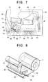
- FIG. 6 is an exterior perspective view of the ticket printing device.
- FIG. 7 is a lateral sectional view of the ticket printing device.
- FIG. 8 is a perspective view of the printing unit in the ticket printing device.
- FIG. 9 is a plan view of the ribbon winding mechanism in the printing unit.
- FIG. 10 is a perspective view illustrating the ribbon sensor in the printing unit.
- FIG. 11 is a block diagram of the control system of the printing unit.
- FIG. 12 is a flowchart illustrating the operation of the control system in FIG. 11.
- An embodiment of the invention will be described with reference to the attached illustrative drawings. The ribbon replacement assembly will be described first, and the ticket printing device second; then the operations of replacing an ink ribbon and setting the printing mode will be described.
- Referring to FIG. 1, the ribbon replacement assembly comprises a
ribbon fixture 2 having two groups of projectingtongues 4, and a pair offlexible members 6 withprojecting tips 7. Thetongues 4 are disposed in two ring-shaped groups, with four tongues in each group. Thetongues 4 have beveled ends and are bent slightly outward. The twoflexible members 6 are positioned so that theirprojecting tips 7 face toward these two groups. Disposed near thebases 8 of theflexible members 6 are a pair ofstoppers 9 for limiting the flexure of theflexible members 6. Theribbon fixture 2 also has twoprojecting guides ribbon fixture 2 and its projectingtongues 4,flexible members 6,stoppers 9, andguides - The ribbon replacement assembly also comprises a
supply spool 14 and take-up spool 16, shown detached from theribbon fixture 2 in FIG. 1. Theink ribbon 18, indicated by dash-dot lines in the drawings, is wound on thesupply spool 14, with its free end attached to the take-up spool 16. When thesupply spool 14 and take-up spool 16 are held in theribbon fixture 2, theink ribbon 18 passes beneath theguides - The take-
up spool 16 has a hollowcylindrical core 20 with aflange 22 at one end. Disposed within thecore 20 at the same end as theflange 22 is an innergrooved ring 24, which is attached to thecore 20 by anannular projection 26 located near the middle of thecore 20. Thesupply spool 14 has the same structure as the take-up spool 16, with a flange, inner grooved ring, and annular projection. - FIG. 2 is a sectional view through line G-G in FIG. 1, showing the inner
grooved ring 24 in more detail. The grooves of the innergrooved ring 24 face inward. The space between the innergrooved ring 24 andcore 20 forms acircular channel 28. - FIG. 3 shows the
supply spool 14 and take-up spool 16 attached to theribbon fixture 2 in a condition suitable for storage, and ready for installation in the ticket printing device. In each spool, thetongues 4 fit into thecircular channel 28 and press outward against thecore 20. The projectingtips 7 of theflexible members 6 fit over and restrain the rims of theflanges 22, thus preventing the spools from being separated from the ribbon fixture. - Referring to the side view in FIG. 4, the
ribbon fixture 2 has alevel base 29, but holds thesupply spool 14 and take-upspool 16 at different heights above thebase 29. Theguides ink ribbon 18 so that it passes around twoguide rollers guide rollers ribbon fixture 2, but are shown here to illustrate their positional relationship to theguides stoppers 9. - FIG. 5 shows the
ribbon fixture 2 by itself, as seen at an angle from above thebase 29, illustrating the shape of thetongues 4 and guide 10, and showing how thebases 8 of the flexible members are attached to theribbon fixture 2. Thestoppers 9 and guide 12 are omitted for clarity. - FIG. 6 shows an exterior view of the ticket-printing
device 33 in which theink ribbon 18 will be installed. Arrow A indicates the direction from which theink ribbon 18 is installed. The ticket-printingdevice 33 has aside cover 34 that swings open from ahinge 36 at the center of the top of the device. The front cover of the ticket-printing device has acontrol panel 38 with control buttons and a liquid crystal display, a dispensingslot 40 from which tickets are dispensed, and aninsertion slot 42 where tickets can be inserted for processing. - Referring to FIG. 7, inside the ticket-printing
device 33 are twohoppers 44 containing fan-foldedticket paper 46. Bothhoppers 44 may contain the same type of ticket-paper 46, or they may contain different types. Theticket paper 46 in eachhopper 44 comprises a continuous strip with perforations between each two adjacent tickets in the strip. Theticket paper 46 from bothhoppers 44 is fed into acutter 48, which cuts one ticket from the appropriate strip ofticket paper 46 in response to a ticket-issuing command, and delivers the cut ticket to aticket transport path 50. - Disposed on this
ticket transport path 50 is a magnetic read-write unit 52 comprising amagnetic writing head 54 and amagnetic reading head 56. Themagnetic writing head 54 records invisible information in a magnetic stripe on the back surface of the ticket. Themagnetic reading head 56 reads the recorded information. - From the magnetic read-
write unit 52, the ticket passes to aprinting unit 58 comprising ablade 59, aplaten 60, athermal printing head 62, and theink ribbon 18 on itssupply spool 14 and take-upspool 16. Theblade 59 guides the ticket between theplaten 60 andthermal printing head 62. The ticket andink ribbon 18 pass together between theplaten 60 andthermal printing head 62. By pressing the ticket andink ribbon 18 against theplaten 60, and selectively heating theink ribbon 18, thethermal printing head 62 prints visible information on the front surface of the ticket. The printed ticket is then ejected through the dispensingslot 40. - The
ink ribbon 18 is used for printing on ordinary ticket paper. If thehoppers 44 contain thermal ticket paper, thesupply spool 14, take-upspool 16, andink ribbon 18 are removed from the ticket-printingdevice 33 so that thethermal printing head 62 can print on the ticket paper in the direct printing mode. - When a ticket (an airplane reservation ticket, for example) is inserted in the
insertion slot 42, the ticket is carried byintake rollers 64 past theblade 59, the invisible magnetic information on the ticket is read by themagnetic reading head 56, and additional magnetic information is written, if necessary, by themagnetic writing head 54. Then the ticket is fed forward into theprinting unit 58, additional visible information is printed if necessary, and the ticket is ejected through the dispensingslot 40. - FIG. 8 is an enlarged view of the
printing unit 58, showing how theink ribbon 18 is fed between theplaten 60 andthermal printing head 62. Theink ribbon 18 is guided by theguide rollers guide roller 30 being disposed on the side near thesupply spool 14, and theguide roller 32 on the side near the take-upspool 16. - FIG. 9 shows the mechanism in the
printing unit 58 for turning thesupply spool 14 and take-upspool 16. Thesupply spool 14 is mounted on asupply spool shaft 66, and the take-upspool 16 on a take-upspool shaft 68. The distance between thesupply spool shaft 66 and take-upspool shaft 68 matches the distance between thecores 20 of thesupply spool 14 and take-upspool 16 when held in theribbon fixture 2. - The
supply spool shaft 66 and take-upspool shaft 68 are mutually similar in structure, each having a large-diameter portion withlongitudinal projections 70 and aflange 72, and a narrow-diameter hollow portion withgrooves 74. The narrow-diameter portion of the spool shaft has a taperedend 76 with aridge 78 that projects over theflange 22 of thespool spool A coil spring 80 is wound around the large-diameter portion of the spool shaft, and pushes the spool in the direction of arrow D. - The take-up
spool shaft 68 extends beyond theflange 72, is supported onbearings 82 in aframe 84 of the printing unit, and is attached to aribbon gear 86. Theribbon gear 86 engages amotor gear 88 attached to afirst stepping motor 90, which thus turns the take-upspool shaft 68. Thesupply spool shaft 66 is similarly turned by asecond stepping motor 92. Thelongitudinal projections 70 on each spool shaft press against the inside surface of thecore 20 of the corresponding spool, and thegrooves 74 engage the innergrooved ring 24 attached to the inside of the core 20, so that the spool is compelled to turn with the spool shaft. - A
lever 94 is mounted on alever shaft 96 near thesupply spool 14. The position of thelever 94 is detected by aribbon sensor 98, which is in this embodiment a photosensor. FIG. 10 shows the sensor arrangement in more detail. Thelever 94 has abeveled edge 100 at one end. When thesupply spool 14 is mounted on thesupply spool shaft 66, the rim of theflange 22 of thesupply spool 14 pushes against this beveled edge, causing thelever 94 to turn in the direction of arrow H, so that theflange 22 can slip under thebeveled edge 100. The inside part of thelever 94, disposed just behind thebeveled edge 100, then rests against the rim of theflange 22. In this position, thebent tip 102 at the other end of thelever 94 is drawn away from theribbon sensor 98, permitting light from alight source 104 to reach theribbon sensor 98. - When the
ink ribbon 18 is not installed, gravity causes thelever 94 to swing in the direction opposite to arrow H, so that thebent end 102 of thelever 94 blocks the light path between thelight source 104 andribbon sensor 98. - FIG. 11 illustrates the control system of the printing unit. This control system communicates via an interface unit (I/F) 106 with a higher-level controller (not visible), which supplies the information to be printed on the ticket. This information is processed by a microcontroller unit (MCU) 108, which controls a
motor driving circuit 110. Thismotor driving circuit 110 supplies exciting current to asolenoid 112 that presses thethermal head 62 against theplaten roller 60, to the steppingmotors spool shafts feed motor 114 that turns theplaten roller 60. - The
microcontroller unit 108 receives signals via anamplifier circuit 116 from theribbon sensor 98, and from acover sensor 118 and a ribbon-end sensor 120, which were not shown in the previous drawings. Thecover sensor 118 senses whether theside cover 34 of the ticket-printing device is open or closed. The ribbon-end sensor 120 senses when the end of theink ribbon 18 has been reached. Theamplifier circuit 116 amplifies the outputs of thesesensors microcontroller unit 108. - The
microcontroller unit 108 is also coupled to thecontrol panel 38, and to amode switching circuit 122. Themode switching circuit 122 controls athermal head driver 124 that supplies energy in the form of electrical current pulses to thethermal printing head 62. - The
thermal head driver 124 is adapted to operate according to at least two different sets of electrical conditions. The electrical conditions in question concern the duration and shape of the electrical current pulses supplied to thethermal printing head 62; these conditions determine the amount and intensity of the heat delivered by thethermal printing head 62 to theink ribbon 18 orticket paper 46. - The
mode switching circuit 122 causes thethermal head driver 124 to operate in two modes: a ribbon printing mode in which electrical conditions optimized for use with theink ribbon 18 are employed; and a direct printing mode in which electrical conditions optimized for direct printing on thermal ticket paper are employed. The mode is selected by a command from themicrocontroller unit 108. - Circuit details of the
mode switching circuit 122 andthermal head driver 124 will be omitted, because circuits for delivering controlled current pulses to a thermal printing head are well known. - Next, the operation of replacing the
ink ribbon 18 will be described. - First, the process of mounting the
ink ribbon 18 and itssupply spool 14 and take-upspool 16 in theribbon fixture 2 will be described. This process is preferably performed by the ribbon manufacturer when the ribbon is manufactured, but can easily be carried out in the field, if necessary, by the person operating the ticket-printing device. - Referring again to FIG. 1, the process begins with the
ink ribbon 18 wound entirely on thesupply spool 14, except that one end is attached to thecore 20 of the take-upspool 16. The first step is to unwind a certain length ofink ribbon 18 from thesupply spool 14. Thesupply spool 14 is then mated with the upper group of fourtongues 4 in FIG. 1, and pushed to the right in the drawing until theflange 22 makes contact with the body of theribbon fixture 2. The beveled ends of thetongues 4 facilitate the insertion of thetongues 4 into thecircular channel 28 shown in FIG. 2. - Next, the
ink ribbon 18 is led beneath theguides spool 16 is mounted on the lower group of fourtongues 4 in FIG. 1. Thesupply spool 14 is then turned to take up slack in theink ribbon 18, so that the ribbon lies flat against theguides tongues 4 on the inside surface of thecores 20 of thesupply spool 14 and take-upspool 16 is sufficient to hold theink ribbon 18 in this position, through not so strong as to prevent thesupply spool 14 and take-upspool 16 from being turned by hand. - As the
supply spool 14 and take-upspool 16 are pushed toward the body of theribbon fixture 2, the edges of theflanges 22 press against the projectingtips 7 of theflexible members 6, so that theflexible members 6 are pushed inward, in the direction of the arrows F in FIG. 3. When theflanges 22 rest against the body of theribbon fixture 2, theflexible members 6 spring back, so that the projectingtips 7 lock theflanges 22 in place. Theink ribbon 18 is now held in a state suitable for storage and transportation. Theink ribbon 18 will not unwind due to careless handling, for example, because the pressure exerted by thetongues 4 prevents thesupply spool 14 and take-upspool 16 from turning freely. - Next, the process of removing an old ribbon from the ticket-printing
device 33 will be described. This process is normally carried out by the operator of the ticket-printingdevice 33, when the ribbon-end sensor 120 senses the end of the ribbon. In this state the ribbon has been fully unwound from thesupply spool 14 and taken up on the take-upspool 16. - The operator begins by opening the
side cover 34 shown in FIG. 6. Thesupply spool 14 and take-upspool 16 are held in place by theridges 78 on the spool shafts, as shown in FIG. 9. To remove thesupply spool 14 and take-upspool 16, the operator presses inward on the tapered ends 76 of thespool shafts supply spool 14 or take-upspool 16 to slip over theridges 78. Thecoil spring 80 pushes against theannular projection 26 supporting the innergrooved ring 24 inside the spool, so that when the operator squeezes the tapered ends 76, the spool springs out to a certain distance in the direction of arrow D. After releasing bothspools ink ribbon 18 by hand. No particular care is required, because theink ribbon 18 is used up and will only be thrown away. - Next the process of installing the
new ink ribbon 18 will be described. Thenew ink ribbon 18 is mounted on aribbon fixture 2 as shown in FIGs. 3 and 4. - As can be seen by comparing FIG. 4 with FIGs. 7, 8, and 9, the
ribbon fixture 2 holds thesupply spool 14 and take-upspool 16 in relative positions matching the relative positions of thesupply spool shaft 66 and take-upspool shaft 68, and holds theink ribbon 18 in the correct position to be threaded under theguide rollers platen 60 andthermal printing head 62. Accordingly, the operator only has to hold thebase 29 of theribbon fixture 2 level, align thecores 20 of thespools spool shafts printing unit 58. Precise alignment is not necessary. Because of the tapered ends 76 of thespool shafts spools spool shafts ribbon fixture 2 until theridges 78 of the spool shafts snap over the inner rims of theflanges 22 of thespools spools spool shafts - Next the operator must remove the
ribbon fixture 2. This is done by pressing inward on thebases 8 of theflexible members 6, in the direction of the arrows E in FIG. 3. The projectingtips 7 of theflexible members 6 then move inward in the direction of the arrows F, disengaging from the outer rims of theflanges 22 of thespools ribbon fixture 2 can now be withdrawn from the ticket-printingdevice 33. - Painstaking care is not required at any point in this procedure. The
guides ribbon fixture 2 automatically thread theink ribbon 18 around theguide rollers platen 60 andthermal printing head 62. Thestoppers 9 prevent the operator from breaking theflexible members 6 by pressing too hard. Theribbon fixture 2 cannot be left inadvertently inside the ticket-printingdevice 33 because theside cover 34 will not close until theribbon fixture 2 is removed, and the ticket-printingdevice 33 will not operate unless theside cover 34 is closed. Thus theribbon fixture 2 simplifies the ribbon replacement job and prevents mistakes, as well as preventing damage to thenew ink ribbon 18. - If the ribbon is replaced while the power of the ticket printing device is switched on, a further safeguard is provided by the
ribbon sensor 98. When the new ribbon is installed, the output of theribbon sensor 98 changes from the off state to the on state as theflange 22 of thesupply spool 14 pushes thebeveled edge 100 of thelever 94 in the direction of arrow H in FIG. 9, withdrawing thebent end 102 of thelever 94 from the path of the light from thelight source 104. If theribbon fixture 2 is pushed sufficiently far for theridges 78 of the spool shafts to lock the supply and take-upspools guide 10 of theribbon fixture 2 blocks the light path, causing the ribbon sensor output to turn off again. When theribbon fixture 2 is withdrawn, the ribbon sensor output turns on again and remains on. Themicrocontroller unit 108 can confirm that ribbon replacement has been correctly performed by detecting the off-on-off-on sequence of ribbon sensor output transitions. - If the
ribbon fixture 2 is pushed insufficiently far, so that theridges 78 of the spool shafts do not lock thespools guide 10 of theribbon fixture 2 will not block the light path to theribbon sensor 98, and only a single off-on transition of the ribbon sensor output will be detected. Themicrocontroller unit 108 can then display a warning message on thecontrol panel 38 when theside cover 34 is closed, advising the operator that the ribbon is not fully installed, thereby avoiding possible printing problems due to wrinkling of theink ribbon 18, or failure of theink ribbon 18 to be properly wound up on the take-upspool 16. - Next the process of setting the printing mode will be described. This process is carried out automatically, without requiring the operator to remember to make any adjustments, as part of an overall control process executed by the control system in FIG. 11.
- FIG. 12 exhibits the relevant part of the control process in the form of a flowchart. The process in FIG. 12 is carried out as part of a reset routine at power up, and is also executed in response to a change in sensor input, e.g. when the
side cover 34 is opened or closed. - In the first step (ST1), the
cover sensor 118 is checked. If theside cover 34 is open, a message to this effect is displayed (step ST2). Display of this cover-open message continues until theside cover 34 is closed. - Next, the
ribbon sensor 98 is checked. If theribbon sensor 98 indicates that anink ribbon 18 is installed, a branch is made to step ST4, in which the ribbon-end sensor 120 is checked. If the ribbon-end sensor 120 indicates that the end of theink ribbon 18 has been reached, a ribbon-end alarm is activated (step ST5). The ribbon-end alarm is, for example, a visible or audible alarm accompanied by a message advising the operator to replace the ribbon. If the ribbon-end sensor 120 does not indicate the end of theink ribbon 18, themode switching circuit 122 is set to the ribbon printing mode (step ST6). - If the
ribbon sensor 98 does not indicate that anink ribbon 18 is installed in step ST3, a transition is made to step ST7, in which the ribbon-end sensor 120 is likewise checked. Since no ribbon is installed, the ribbon-end sensor 120 will normally indicate the end of the ribbon, in which case themode switching circuit 122 is set to the direct printing mode (step ST8). If the ribbon-end sensor 120 does not indicate the end of the ribbon, an error message is displayed (step ST9), advising the operator to check the sensors for a possible electrical fault or the presence of a foreign object. - After the ribbon printing mode or direct printing mode has been set in step ST6 or step ST8, the mode setting is displayed on the
control panel 38 and the operator is asked to confirm the mode setting. If the operator presses a confirmation button, the mode setting is accepted, the setting procedure ends, and the ticket-printing device is ready to print. If the operator does not confirm the mode setting, printing is deferred until the operator takes further action, such as installing or removing anink ribbon 18 or changing the ticket paper. After such action, the entire procedure from step ST1 is performed again. - Once the printing mode has been set, the ticket-printing
device 33 continues to operate in the selected mode until power is switched off, or a reset button is pressed, or theside cover 34 is opened, or the end of theink ribbon 18 is detected. - Since the mode is set automatically, and the operator is only called on to confirm the mode setting, printing problems due to forgotten or incorrectly performed mode adjustments are eliminated. Optimum printing is obtained in both the ribbon printing mode and direct printing mode, without the need for any particular care on the operator's part, and ticket legibility is improved, as compared with ticket-printing devices that print with the same electrical conditions in both modes.
- The invention is not restricted to the embodiment described above; the structure of both the ticket printing device and the replacement ribbon assembly can be modified in various ways. To give just one example, the
ribbon fixture 2 does not have to be made of molded plastic; other materials may be used, including both disposable or recyclable materials such as stiff cardboard, and durable materials that enable the ribbon fixture to be used repeatedly. Those skilled in the art will recognize numerous further variations that are possible within the scope of the invention.
Claims (12)
- A ribbon replacement assembly for a ticket-printing device (33), having an ink ribbon (18) wound on a supply spool (14) for installation on a supply spool shaft (66) in said ticket-printing device (33), and a take-up spool (16) for installation on a take-up spool shaft (68) in said ticket-printing device (33), one end of said ink ribbon (18) being attached to said take-up spool (16), comprising:a ribbon fixture (2) for releasably holding said supply spool (14) and said take-up spool (16) in relative positions matching relative positions of said supply spool shaft (66) and said take-up spool shaft (68), so that said supply spool (14) and said take-up spool (16) can be slipped onto said supply spool shaft (66) and said take-up spool shaft (68) while held in said ribbon fixture (2), then released from said ribbon fixture (2), allowing said ribbon fixture (2) to be withdrawn from said ticket-printing device (33) while leaving said supply spool (14), said take-up spool (16), and said ink ribbon (18) installed in said ticket-printing device (33).
- The ribbon replacement assembly of claim 1, wherein said ribbon fixture (2) also holds said supply spool (14) and said take-up spool (16) while said supply spool (14), said take-up spool (16), and said ink ribbon (18) are being stored prior to installation in said ticket-printing device (33).
- The ribbon replacement assembly of claim 1, wherein said ticket-printing device (33) has a ribbon sensor (98) for detecting presence of said ink ribbon (18), and when said ink ribbon (18) is correctly installed while being held in said ribbon fixture (2), said ribbon sensor (98) detects a part of said ribbon fixture (2), thereby confirming correct installation of said ink ribbon (18).
- The ribbon replacement assembly of claim 1, also comprising at least one guide (10) attached to said ribbon fixture (2), for guiding said ink ribbon (18) so that said ink ribbon (18) follows a certain path from said supply spool (14) to said take-up spool (16).
- The ribbon replacement assembly of claim 4, wherein said ticket-printing device (33) has a ribbon sensor (98) for detecting presence of said ink ribbon (18), and when said ink ribbon (18) is correctly installed while being held in said ribbon fixture (2), said ribbon sensor (98) detects a part of said guide (10), thereby confirming correct installation of said ink ribbon (18).
- The ribbon replacement assembly of claim 4, wherein said ticket-printing device (33) has a printing head (62) and a platen (60), and said guide (10) guides said ink ribbon (18) between said printing head (62) and said platen (60) when said ink ribbon (18) is being installed in said ticket-printing device (33).
- The ribbon replacement assembly of claim 1, wherein:said supply spool (14) and said take-up spool (16) have respective circular channels (28) with inside surfaces; andsaid ribbon fixture (2) has a plurality of tongues (4) which are inserted into the circular channels (28) of said supply spool (14) and said take-up spool (16) when said supply spool (14) and said take-up spool (16) are held in said ribbon fixture (2), for pressing outward against the inside surfaces of said circular channels (28), thereby preventing said supply spool (14) and said take-up spool (16) from turning freely.
- The ribbon replacement assembly of claim 1, wherein said supply spool (14) and said take-up spool (16) have respective flanges (22), also comprising a pair of flexible members (6) with projecting tips (7) for restraining the flanges (22) of said supply spool (14) and said take-up spool (16).
- The ribbon replacement assembly of claim 8, wherein said supply spool (14) and said take-up spool (16) are released from said ribbon fixture (2) by inward pressure on said flexible members (6), causing said projecting tips (7) to disengage from said flanges (22).
- A ticket-printing device (33) having a printing head (62) for printing information on ticket paper (46), said printing head (62) being capable of printing both with and without an ink ribbon (18), comprising:a head driver (124) for supplying electrical energy to said printing head (62) under at least two different sets of electrical conditions;a ribbon sensor (98) for sensing presence and absence of said ink ribbon (18); anda mode-switching circuit (122) coupled to said head driver (124) and said ribbon sensor (98), for directing said head driver (124) to supply said electrical energy under one set of electrical conditions when said ribbon sensor (98) detects that said ink ribbon (18) is present, and under a different set of electrical conditions when said ribbon sensor (98) detects that said ink ribbon (18) is absent.
- The ticket-printing device (33) of claim 10, wherein:when said ribbon sensor (98) detects that said ink ribbon (18) is present, said printing head (62) prints by heating said ink ribbon (18), thereby causing transfer of ink from said ink ribbon (18) to said ticket paper (46); andwhen said ribbon sensor (98) detects that said ink ribbon (18) is absent, said printing head (62) prints by heating said ticket paper (46) directly, thereby causing said ticket paper (46) to change color.
- The ticket-printing device (33) of claim 10, wherein said ink ribbon (18) is held in a ribbon fixture (2) while being installed in said ticket-printing device (33), said ribbon fixture (2) being removed from said ticket-printing device (33) after said ink ribbon (18) has been installed, and said ribbon sensor (98) detects whether said ink ribbon (18) is correctly installed by detecting part of said ribbon fixture (2).
Applications Claiming Priority (3)
| Application Number | Priority Date | Filing Date | Title |
|---|---|---|---|
| JP269927/95 | 1995-10-18 | ||
| JP26992795 | 1995-10-18 | ||
| JP26992795A JP3330476B2 (en) | 1995-10-18 | 1995-10-18 | Adapter case and ticket processing device using the adapter case for mounting ink ribbon |
Publications (3)
| Publication Number | Publication Date |
|---|---|
| EP0769762A2 true EP0769762A2 (en) | 1997-04-23 |
| EP0769762A3 EP0769762A3 (en) | 1999-01-07 |
| EP0769762B1 EP0769762B1 (en) | 2002-09-11 |
Family
ID=17479144
Family Applications (1)
| Application Number | Title | Priority Date | Filing Date |
|---|---|---|---|
| EP96116312A Expired - Lifetime EP0769762B1 (en) | 1995-10-18 | 1996-10-11 | Ribbon assembly adapted for easy ribbon replacement in a ticket-printing device |
Country Status (4)
| Country | Link |
|---|---|
| US (1) | US5813774A (en) |
| EP (1) | EP0769762B1 (en) |
| JP (1) | JP3330476B2 (en) |
| DE (1) | DE69623558D1 (en) |
Cited By (2)
| Publication number | Priority date | Publication date | Assignee | Title |
|---|---|---|---|---|
| WO2004011268A1 (en) * | 2002-07-31 | 2004-02-05 | Datacard Corporation | Supply items for printers and the like, and method of loading supply items |
| EP1733896A1 (en) | 2005-06-17 | 2006-12-20 | Printronix, Inc. | Ribbon hub and spool assembly |
Families Citing this family (8)
| Publication number | Priority date | Publication date | Assignee | Title |
|---|---|---|---|---|
| JPH1110929A (en) * | 1997-06-25 | 1999-01-19 | Sony Corp | Ink ribbon, printer apparatus and printing method |
| JPH1110979A (en) * | 1997-06-25 | 1999-01-19 | Sony Corp | Ink ribbon and printer |
| EP0919393B1 (en) * | 1997-11-27 | 2004-02-11 | Esselte N.V. | Refillable tape cassette |
| IT1319295B1 (en) * | 2000-04-28 | 2003-10-10 | Giancarlo Zanetti | MAGNETIC BAND WITH ADHESIVE LAYER. |
| KR101427426B1 (en) | 2007-01-25 | 2014-09-17 | 니스카 가부시키가이샤 | Cartridge for printer, cartridge installed/detached detection method and printer apparatus |
| TWM331707U (en) * | 2007-11-28 | 2008-05-01 | Icp Electronics Inc | Lottery ticket printer |
| JP4294074B1 (en) * | 2008-02-08 | 2009-07-08 | 株式会社サトー知識財産研究所 | Thermal printer |
| US10350905B2 (en) | 2017-01-26 | 2019-07-16 | Datamax-O'neil Corporation | Detecting printing ribbon orientation |
Citations (4)
| Publication number | Priority date | Publication date | Assignee | Title |
|---|---|---|---|---|
| EP0361693A2 (en) * | 1988-09-02 | 1990-04-04 | Kabushiki Kaisha Shinsei Industries | Desk top label printer |
| JPH02204074A (en) * | 1989-02-03 | 1990-08-14 | Hitachi Ltd | Auxiliary package mounting ink film |
| EP0386982A2 (en) * | 1989-03-08 | 1990-09-12 | Tokyo Electric Co., Ltd. | Method and apparatus for loading ink ribbon |
| DE4442511A1 (en) * | 1994-11-30 | 1996-06-05 | Esselte Meto Int Gmbh | Method and device for loading an ink ribbon into a printer |
Family Cites Families (5)
| Publication number | Priority date | Publication date | Assignee | Title |
|---|---|---|---|---|
| JPS63306067A (en) * | 1987-06-08 | 1988-12-14 | スター精密株式会社 | Heat transfer printer |
| US4998834A (en) * | 1989-10-20 | 1991-03-12 | Monarch Marking Systems, Inc. | Slide assembly for mounting a print ribbon |
| US5383733A (en) * | 1992-07-24 | 1995-01-24 | Summagraphics Corporation | Ribbon cassette for a printer |
| GB9401544D0 (en) * | 1994-01-27 | 1994-03-23 | Ici Plc | Thermal transfer ribbon cassette system |
| US5433540A (en) * | 1994-03-03 | 1995-07-18 | Xerox Corporation | Combined spool retainer and installation device |
-
1995
- 1995-10-18 JP JP26992795A patent/JP3330476B2/en not_active Expired - Fee Related
-
1996
- 1996-09-30 US US08/723,802 patent/US5813774A/en not_active Expired - Fee Related
- 1996-10-11 EP EP96116312A patent/EP0769762B1/en not_active Expired - Lifetime
- 1996-10-11 DE DE69623558T patent/DE69623558D1/en not_active Expired - Lifetime
Patent Citations (4)
| Publication number | Priority date | Publication date | Assignee | Title |
|---|---|---|---|---|
| EP0361693A2 (en) * | 1988-09-02 | 1990-04-04 | Kabushiki Kaisha Shinsei Industries | Desk top label printer |
| JPH02204074A (en) * | 1989-02-03 | 1990-08-14 | Hitachi Ltd | Auxiliary package mounting ink film |
| EP0386982A2 (en) * | 1989-03-08 | 1990-09-12 | Tokyo Electric Co., Ltd. | Method and apparatus for loading ink ribbon |
| DE4442511A1 (en) * | 1994-11-30 | 1996-06-05 | Esselte Meto Int Gmbh | Method and device for loading an ink ribbon into a printer |
Cited By (5)
| Publication number | Priority date | Publication date | Assignee | Title |
|---|---|---|---|---|
| WO2004011268A1 (en) * | 2002-07-31 | 2004-02-05 | Datacard Corporation | Supply items for printers and the like, and method of loading supply items |
| US6997629B2 (en) | 2002-07-31 | 2006-02-14 | Datacard Corporation | Supply items for printers and the like, and method of loading supply items |
| CN100396503C (en) * | 2002-07-31 | 2008-06-25 | 咨询卡有限公司 | Supply items for printers and the like, and method of loading supply items |
| EP1733896A1 (en) | 2005-06-17 | 2006-12-20 | Printronix, Inc. | Ribbon hub and spool assembly |
| EP2243634A1 (en) * | 2005-06-17 | 2010-10-27 | Printronix, Inc. | Ribbon hub and spool assembly |
Also Published As
| Publication number | Publication date |
|---|---|
| JPH09115010A (en) | 1997-05-02 |
| EP0769762B1 (en) | 2002-09-11 |
| US5813774A (en) | 1998-09-29 |
| JP3330476B2 (en) | 2002-09-30 |
| DE69623558D1 (en) | 2002-10-17 |
| EP0769762A3 (en) | 1999-01-07 |
Similar Documents
| Publication | Publication Date | Title |
|---|---|---|
| EP0769762B1 (en) | Ribbon assembly adapted for easy ribbon replacement in a ticket-printing device | |
| WO2009107534A1 (en) | Tape cassette, tape making apparatus and tape making system | |
| CN103568589B (en) | Printing equipment and Method of printing | |
| JPH058472A (en) | Printing device and its control | |
| US5553952A (en) | Reusable ink ribbon cassette for a label printer, the cassette being capable of accommodating ink ribbons having different widths | |
| GB2440728A (en) | Printing on multilayered tape | |
| US5959652A (en) | Thermal ink ribbon cassette for mailing machines | |
| JP2006306511A (en) | Rolled sheet cue mechanism, paper feeding cassette and printer | |
| US7563044B2 (en) | Identifying compatible combination for a thermal printer | |
| EP0929403A1 (en) | Arrangement for automatic setting of printers and materials therefor | |
| JP2943747B2 (en) | Label printer | |
| JPH04251059A (en) | Thermal paper cartridge for facsimile machine | |
| EP3374190B1 (en) | Ribbon supply mounting | |
| JPS6073888A (en) | Color printer | |
| JPH04252559A (en) | Plain paper cartridge used for facsimile machine | |
| JP2946739B2 (en) | Printing apparatus and control method thereof | |
| JPH11227994A (en) | Recording device and housing box for paper of recording device | |
| JPS6073866A (en) | Printer apparatus | |
| JP2593671B2 (en) | Ink ribbon cassette and recording apparatus equipped with the cassette | |
| JPH05286196A (en) | Color thermal transfer recording device | |
| JPS6212030B2 (en) | ||
| JPH06106828A (en) | Ink ribbon and printing device | |
| JPS62270375A (en) | Ink ribbon apparatus | |
| JP2007008040A (en) | Thermal transfer apparatus for cards | |
| JP2000190605A (en) | Printing device and tape cassette used for the device |
Legal Events
| Date | Code | Title | Description |
|---|---|---|---|
| PUAI | Public reference made under article 153(3) epc to a published international application that has entered the european phase |
Free format text: ORIGINAL CODE: 0009012 |
|
| AK | Designated contracting states |
Kind code of ref document: A2 Designated state(s): DE FR NL |
|
| PUAL | Search report despatched |
Free format text: ORIGINAL CODE: 0009013 |
|
| AK | Designated contracting states |
Kind code of ref document: A3 Designated state(s): DE FR NL |
|
| 17P | Request for examination filed |
Effective date: 19990521 |
|
| 17Q | First examination report despatched |
Effective date: 20010626 |
|
| GRAG | Despatch of communication of intention to grant |
Free format text: ORIGINAL CODE: EPIDOS AGRA |
|
| RTI1 | Title (correction) |
Free format text: RIBBON ASSEMBLY ADAPTED FOR EASY RIBBON REPLACEMENT IN A TICKET-PRINTING DEVICE |
|
| GRAG | Despatch of communication of intention to grant |
Free format text: ORIGINAL CODE: EPIDOS AGRA |
|
| GRAG | Despatch of communication of intention to grant |
Free format text: ORIGINAL CODE: EPIDOS AGRA |
|
| GRAH | Despatch of communication of intention to grant a patent |
Free format text: ORIGINAL CODE: EPIDOS IGRA |
|
| GRAH | Despatch of communication of intention to grant a patent |
Free format text: ORIGINAL CODE: EPIDOS IGRA |
|
| GRAA | (expected) grant |
Free format text: ORIGINAL CODE: 0009210 |
|
| AK | Designated contracting states |
Kind code of ref document: B1 Designated state(s): DE FR NL |
|
| REF | Corresponds to: |
Ref document number: 69623558 Country of ref document: DE Date of ref document: 20021017 |
|
| ET | Fr: translation filed | ||
| PG25 | Lapsed in a contracting state [announced via postgrant information from national office to epo] |
Ref country code: DE Free format text: LAPSE BECAUSE OF FAILURE TO SUBMIT A TRANSLATION OF THE DESCRIPTION OR TO PAY THE FEE WITHIN THE PRESCRIBED TIME-LIMIT Effective date: 20021212 |
|
| PLBE | No opposition filed within time limit |
Free format text: ORIGINAL CODE: 0009261 |
|
| STAA | Information on the status of an ep patent application or granted ep patent |
Free format text: STATUS: NO OPPOSITION FILED WITHIN TIME LIMIT |
|
| 26N | No opposition filed |
Effective date: 20030612 |
|
| PGFP | Annual fee paid to national office [announced via postgrant information from national office to epo] |
Ref country code: NL Payment date: 20071015 Year of fee payment: 12 |
|
| PGFP | Annual fee paid to national office [announced via postgrant information from national office to epo] |
Ref country code: FR Payment date: 20071009 Year of fee payment: 12 |
|
| NLV4 | Nl: lapsed or anulled due to non-payment of the annual fee |
Effective date: 20090501 |
|
| REG | Reference to a national code |
Ref country code: FR Ref legal event code: ST Effective date: 20090630 |
|
| PG25 | Lapsed in a contracting state [announced via postgrant information from national office to epo] |
Ref country code: NL Free format text: LAPSE BECAUSE OF NON-PAYMENT OF DUE FEES Effective date: 20090501 |
|
| PG25 | Lapsed in a contracting state [announced via postgrant information from national office to epo] |
Ref country code: FR Free format text: LAPSE BECAUSE OF NON-PAYMENT OF DUE FEES Effective date: 20081031 |