EP0769365A2 - Blank feeder - Google Patents
Blank feeder Download PDFInfo
- Publication number
- EP0769365A2 EP0769365A2 EP96202864A EP96202864A EP0769365A2 EP 0769365 A2 EP0769365 A2 EP 0769365A2 EP 96202864 A EP96202864 A EP 96202864A EP 96202864 A EP96202864 A EP 96202864A EP 0769365 A2 EP0769365 A2 EP 0769365A2
- Authority
- EP
- European Patent Office
- Prior art keywords
- blanks
- magazine
- conveyor
- blank
- detection signal
- Prior art date
- Legal status (The legal status is an assumption and is not a legal conclusion. Google has not performed a legal analysis and makes no representation as to the accuracy of the status listed.)
- Granted
Links
Images


Classifications
-
- B—PERFORMING OPERATIONS; TRANSPORTING
- B65—CONVEYING; PACKING; STORING; HANDLING THIN OR FILAMENTARY MATERIAL
- B65H—HANDLING THIN OR FILAMENTARY MATERIAL, e.g. SHEETS, WEBS, CABLES
- B65H1/00—Supports or magazines for piles from which articles are to be separated
- B65H1/08—Supports or magazines for piles from which articles are to be separated with means for advancing the articles to present the articles to the separating device
- B65H1/24—Supports or magazines for piles from which articles are to be separated with means for advancing the articles to present the articles to the separating device with means for relieving or controlling pressure of the pile
-
- B—PERFORMING OPERATIONS; TRANSPORTING
- B31—MAKING ARTICLES OF PAPER, CARDBOARD OR MATERIAL WORKED IN A MANNER ANALOGOUS TO PAPER; WORKING PAPER, CARDBOARD OR MATERIAL WORKED IN A MANNER ANALOGOUS TO PAPER
- B31B—MAKING CONTAINERS OF PAPER, CARDBOARD OR MATERIAL WORKED IN A MANNER ANALOGOUS TO PAPER
- B31B50/00—Making rigid or semi-rigid containers, e.g. boxes or cartons
- B31B50/006—Controlling; Regulating; Measuring; Improving safety
-
- B—PERFORMING OPERATIONS; TRANSPORTING
- B31—MAKING ARTICLES OF PAPER, CARDBOARD OR MATERIAL WORKED IN A MANNER ANALOGOUS TO PAPER; WORKING PAPER, CARDBOARD OR MATERIAL WORKED IN A MANNER ANALOGOUS TO PAPER
- B31B—MAKING CONTAINERS OF PAPER, CARDBOARD OR MATERIAL WORKED IN A MANNER ANALOGOUS TO PAPER
- B31B50/00—Making rigid or semi-rigid containers, e.g. boxes or cartons
- B31B50/02—Feeding or positioning sheets, blanks or webs
- B31B50/04—Feeding sheets or blanks
- B31B50/06—Feeding sheets or blanks from stacks
- B31B50/062—Feeding sheets or blanks from stacks from the underside of a magazine
-
- B—PERFORMING OPERATIONS; TRANSPORTING
- B65—CONVEYING; PACKING; STORING; HANDLING THIN OR FILAMENTARY MATERIAL
- B65H—HANDLING THIN OR FILAMENTARY MATERIAL, e.g. SHEETS, WEBS, CABLES
- B65H2511/00—Dimensions; Position; Numbers; Identification; Occurrences
- B65H2511/50—Occurence
- B65H2511/51—Presence
-
- B—PERFORMING OPERATIONS; TRANSPORTING
- B65—CONVEYING; PACKING; STORING; HANDLING THIN OR FILAMENTARY MATERIAL
- B65H—HANDLING THIN OR FILAMENTARY MATERIAL, e.g. SHEETS, WEBS, CABLES
- B65H2513/00—Dynamic entities; Timing aspects
- B65H2513/40—Movement
Definitions
- the present invention relates to a feeder for supplying a container forming apparatus with blanks for containers to be filled, for example, with milk, more particularly blanks which are folded flat so as to be unfoldable into tubes of square or rectangular cross section.
- Such feeders already known comprise a magazine having an outlet at a lower end thereof for accommodating a plurality of blanks as closely arranged from the lower end to the upper end thereof in the form of a stack so that the blanks are movable inside the magazine toward the outlet under gravity, and takeout means for taking out the blanks one by one from the outlet while unfolding each blank into a square or rectangular tube and transporting the blank to guide rails for guiding the blank to a container forming apparatus.
- the pressure acting on the blank in the lowermost position at the outlet varies with variations in the quantity of blanks remaining in the magazine, presenting difficulty in controlling the operation of the takeout means.
- the higher the magazine the greater are the pressure variations.
- the problem may be avoidable by reducing the height of the magazine, but this requires the cumbersome procedure of supplying blanks to the magazine frequently.
- An object of the present invention is to provide a blank feeder which comprises a magazine permitting a constant quantity of blanks to remain therein and which assures a facilitated blank feeding operation.
- the present invention provides a blank feeder which comprises a magazine having an outlet at a lower end thereof for accommodating a plurality of blanks as arranged from the lower end to an upper end thereof in the form of a stack so that the blanks are movable inside the magazine toward the outlet under gravity, a conveyor providing a path of transport for supporting the lower ends of a plurality of blanks as arranged closely face-to-face on the conveyor from a terminal end of the path to a starting end thereof without allowing the blanks on the conveyor to move on the conveyor under gravity, the blank at the terminal end of the path being supported at its upper end by the uppermost blank within the magazine, a sensor for producing a non-detection signal when the quantity of blanks remaining within the magazine has decreased to not greater than a predetermined value and producing a detection signal upon the quantity of remaining blanks exceeding the predetermined value, and drive means for driving the conveyor in response to the non-detection signal of the sensor and discontinuing the operation of the conveyor in response to the detection signal.
- blanks are delivered from the conveyor to the magazine when the quantity of blanks within the magazine has decreased to not greater than a predetermined value, and the delivery is discontinued upon the remaining quantity exceeding the predetermined value.
- the quantity of blanks remaining in the magazine can therefore be made constant at all times, permitting blanks to be taken out from the magazine smoothly.
- Blanks are supplied onto the conveyor when the quantity of blanks remaining on the conveyor has decreased to not greater than a specified value. Accordingly, blanks can be supplied easily.
- the path of movement of the blanks inside the magazine makes an angle of 105 to 165 deg with the transport path of the conveyor, and the sensor is so disposed as to produce a non-detection signal or detection signal by detecting the displacement of the upper end of the blank at the terminal end of the transport path due to an alteration in the angle of the same blank in accordance with the variation in the quantity of blanks remaining within the magazine.
- the path of movement of blanks within the magazine is orthogonal to an axial extension line of a container forming mandrel as directed obliquely downward and halted at a feed station, and the magazine has its outlet opposed to the axial extension line from above.
- front and rear are to be used based on FIG. 1; the left-hand side of the drawing will be referred to as “front,” and the opposite side as “rear.”
- the terms “right” and “left” will be used for the feeder as it is seen from behind toward the front.
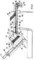
- one of radial mandrels 11 of an intermittently drivable rotary body for forming containers is halted at a blank feed station, as inclined obliquely rearwardly downward at an angle of 45 deg with a horizontal
- the illustrated blank feeder is adapted to selectively feed to the mandrel 11 three kinds of blanks B which are different in height, i.e., tall containers, medium-sized containers and low containers.
- the feeder comprises a magazine 13 disposed in the rear of the mandrel 11 and having a lower-end outlet 12 facing obliquely forwardly downward for accommodating a plurality of flat blanks B in the form of a stack, a conveyor 14 having a forwardly extending horizontal path of transport for transporting the blanks B to be accommodated in the magazine 13, with the front end of the transport path opposed to the interior of the magazine 13, a picker 15 so disposed as to be movable toward or away from the outlet 12 for taking out blanks B from the outlet 12 one by one while unfolding each blank B into a square or rectangular tube, a pair of guide rails 16 extending from a position opposed to the outlet 12 to a position close to the outer end of the mandrel 11 along the axial extension line or the mandrel 11 and inclined at the same angle as
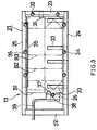
- the magazine 13 comprises a rectangular frame 21 elongated along the axial extension liner surrounding the outlet 12 and inclined at the same angle as the mandrel 11, i.e., at 45 deg when seen from one side.
- the frame 21 comprises an upper frame member 22, right and left side frame members 25,24 and a movable member 26 movable inside the frame 21 longitudinally thereof.
- the lower frame member 23 is provided on its lower face with a blank opening fixed nail 31 projecting inwardly of the frame 21 and has two lower guide rods 32 extending upright from its upper face.
- the left frame member 24 is provided on the lower face thereof with four arcuate guide plates 33 for guiding the left edge of the blank B when the blank is unfolded, and has three guide rods 34 extending upright from the upper face thereof.
- the right frame member 25 is provided on the lower face thereof with a blank support bar 35 having one end projecting inwardly of the frame 21, and has three right guide rods 36 extending upright from the upper face thereof.
- the movable member 26 has a blank opening movable nail 37 on its lower face, an upper guide rod 38 on its upper face and a pusher arm 39 on a side face thereof.
- FIG 3 shows, as accommodated in the magazine 13, a tall blank B1 in dot-and-dash lines, a medium-sized blank B2 in a two-dot-and-dash line, and a low blank B3 in a three-dot-and-dash line.
- the position of the movable member 26 is adjustable in accordance with the height of the blanks B1, B2, B3.
- a photoelectric tube 41 for detecting the tall blank is attached to the upper end of the right guide rod 36 positioned first from above, and a photoelectric tube 42 for detecting the medium-sized blank and a photoelectric tube 43 for detecting the low blank are attached to the upper end of the right guide rod 36 positioned second.
- the conveyor 14 comprises a frame 53 supported by the upper ends of front and rear posts 51, 52, a horizontal front driven shaft 54 and rear drive shaft 55 provided respectively at the front and rear ends of the frame 53 and extending transversely of the feeder, a pair of right and left front pulleys 56 fixed to the driven shaft 54, a pair of right and left rear pulleys 57 fixed to the drive shaft 55, a pair of right and left toothed belts 58 each reeved around the front pulley 56 and the rear pulley 57 at one of the right and left sides, right and left side guide plates 59 arranged respectively at the right and left sides of the pair of endless belts 58 externally thereof, and a pair of right and left arcuate bridge plates 61 extending from positions laterally outside the pair of front pulleys 56 to the upper ends of the respective lower guide rods 32.
- a photoelectric tube 62 is disposed at the right side of front end of the right belt 58 for detection to discontinue picking, and a blank supply alarm photoelectric tube 63 is disposed to the rear of the tube 62.
- a stopper 64 in the form of an L-shaped plate for preventing blanks from falling down is provided across the upper path of travel of the belts 58.
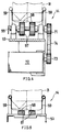
- a driven pulley 71 is fixed to the right end of the drive shaft weight 55.
- a motor 72 installed below the drive shaft 55 has an output shaft fixedly carrying a drive pulley 73.
- a belt 74 is reeved around the driven pulley 71 and the drive pulley 73.
- FIG. 5 shows that each of the belts 58 bears on a slip plate 81 when in the upper path of travel
- the blanks B within the magazine 13 move at an angle of 45 deg with respect to a horizontal, in other words, at an angle of 135 deg with the path of transport of the conveyor 14.
- Tall blanks B1 are fed to the mandrel by the operation to be described next with reference to FIG. 6.
- FIG. 6, diagram (a) shows that blanks B1 in a quantity slightly less than when filling up the magazine 13 are accommodated as stacked up within the magazine.
- the uppermost blank B1 is positioned at a level lower than the photoelectric tube 41 for detecting tall blanks.
- the stopper 64 bears on the lower end of the rearmost blank B1, and the upper end of the foremost blank B1 is supported by the uppermost blank B1 in the magazine 13.
- the tube 41 for detecting the tall blank B1 produces a non-detection signal, whereupon the conveyor 14 is driven in response to the non-detection signal.
- the conveyor 14 delivers the blanks B1 thereon successively from the foremost position. This raises the level of the uppermost blank B1 within the magazine 13. With this movement, the inclination of blanks B1 with respect to a horizontal gradually increases.
- the tube 41 for detecting tall blanks produces a detection signal, in response to which the conveyor 14 is halted to interrupt the delivery of blanks B1 into the magazine 13.
- the level of the uppermost blank B1 inside the magazine 13 descends, gradually decreasing the inclination of the blanks on the conveyor 14 with respect to the horizontal.
- the tube 41 for tall blanks B produces a non-detection signal again, whereupon the conveyor 14 is driven in response to the signal to deliver blanks B1 into the magazine 13.
- FIG. 6, (b) shows the blank supply alarm photoelectric tube 63 while it is producing a non-detection signal. It is desirable to replenish the conveyor 14 with new blanks when this signal is given. The replenishment is made manually by the worker by retracting the stopper 64 and placing blanks B1 in the emptied space.
- the quantity of blanks B1 on the conveyor 14 further decreases to the state shown in FIG. 6, (c), whereupon the photoelectric tube 62 for detection to discontinue picking produces a non-detection signal.
- the picker 15 is then forcibly brought out of operation to discontinue the operation of taking out blanks from the magazine 13.
- FIG. 7, (a) shows an operation to feed medium sized blanks B2.
- the photoelectric tube 42 for detecting medium-sized blanks produces a non-detection signal and detection signal for controlling the conveyor 14 for driving or stopping.
- FIG. 7, (b) shows an operation to feed low blanks B3 using the non-detection and detection signals of the photoelectric tube 43 for detecting low blanks.
- the non-detection signal and detection signal of the tube 42 for detecting medium-sized blanks are used in feeding tall blanks B1 and when the state of FIG. 6, (a) is brought about, blanks B1 on the conveyor 14 are present in front of the tube 42 for the medium-sized blank, so that the tube 42 produces no non-detection signal.
- the quantity of blanks B1 in the magazine 13 decreases from the state of FIG. 6, (a)
- the medium-sized blank detection tube 42 produces a non-detection signal.
Abstract
Description
- The present invention relates to a feeder for supplying a container forming apparatus with blanks for containers to be filled, for example, with milk, more particularly blanks which are folded flat so as to be unfoldable into tubes of square or rectangular cross section.
- Such feeders already known comprise a magazine having an outlet at a lower end thereof for accommodating a plurality of blanks as closely arranged from the lower end to the upper end thereof in the form of a stack so that the blanks are movable inside the magazine toward the outlet under gravity, and takeout means for taking out the blanks one by one from the outlet while unfolding each blank into a square or rectangular tube and transporting the blank to guide rails for guiding the blank to a container forming apparatus.
- With the conventional apparatus, the pressure acting on the blank in the lowermost position at the outlet varies with variations in the quantity of blanks remaining in the magazine, presenting difficulty in controlling the operation of the takeout means. Especially, the higher the magazine, the greater are the pressure variations. The problem may be avoidable by reducing the height of the magazine, but this requires the cumbersome procedure of supplying blanks to the magazine frequently.
- An object of the present invention is to provide a blank feeder which comprises a magazine permitting a constant quantity of blanks to remain therein and which assures a facilitated blank feeding operation.
- The present invention provides a blank feeder which comprises a magazine having an outlet at a lower end thereof for accommodating a plurality of blanks as arranged from the lower end to an upper end thereof in the form of a stack so that the blanks are movable inside the magazine toward the outlet under gravity, a conveyor providing a path of transport for supporting the lower ends of a plurality of blanks as arranged closely face-to-face on the conveyor from a terminal end of the path to a starting end thereof without allowing the blanks on the conveyor to move on the conveyor under gravity, the blank at the terminal end of the path being supported at its upper end by the uppermost blank within the magazine, a sensor for producing a non-detection signal when the quantity of blanks remaining within the magazine has decreased to not greater than a predetermined value and producing a detection signal upon the quantity of remaining blanks exceeding the predetermined value, and drive means for driving the conveyor in response to the non-detection signal of the sensor and discontinuing the operation of the conveyor in response to the detection signal.
- With the blank feeder of the present invention, blanks are delivered from the conveyor to the magazine when the quantity of blanks within the magazine has decreased to not greater than a predetermined value, and the delivery is discontinued upon the remaining quantity exceeding the predetermined value. The quantity of blanks remaining in the magazine can therefore be made constant at all times, permitting blanks to be taken out from the magazine smoothly. Blanks are supplied onto the conveyor when the quantity of blanks remaining on the conveyor has decreased to not greater than a specified value. Accordingly, blanks can be supplied easily.
- Preferably, the path of movement of the blanks inside the magazine makes an angle of 105 to 165 deg with the transport path of the conveyor, and the sensor is so disposed as to produce a non-detection signal or detection signal by detecting the displacement of the upper end of the blank at the terminal end of the transport path due to an alteration in the angle of the same blank in accordance with the variation in the quantity of blanks remaining within the magazine.
- When the quantity of blanks remaining inside the magazine decreases, the inclination of the blank at the terminal end of the transport path with respect to a horizontal reduces, while the inclination of the blank at the terminal and of the path with respect to the horizontal increases with increasing quantity of blanks remaining in the magazine. Accordingly, minute variations in the angle of the blank are easily detectable by detecting the displacement of the upper end of the blank. The quantity of blanks remaining in the magazine, even if small, is detectable without being interfered with by the blanks on the conveyor.
- The path of movement of blanks within the magazine is orthogonal to an axial extension line of a container forming mandrel as directed obliquely downward and halted at a feed station, and the magazine has its outlet opposed to the axial extension line from above.
-
- FIG. 1 is a side elevation of a blank feeder embodying the invention;
- FIG. 2 is a perspective view of the same;
- FIG. 3 is a sectional view of a magazine of the feeder;
- FIG. 4 is a view in vertical cross section of a rear end portion of a conveyor of the feeder;
- FIG. 5 is a view in vertical cross section of a lengthwise intermediate portion or the conveyor,
- FIG. 6 includes diagrams for illustrating a blank feeding operation; and
- FIG. 7 includes diagrams each showing the operation of feeding blanks of different height.
- In the following description, the terms "front" and "rear" are to be used based on FIG. 1; the left-hand side of the drawing will be referred to as "front," and the opposite side as "rear." The terms "right" and "left" will be used for the feeder as it is seen from behind toward the front.
- With reference to FIG. 1, one of
radial mandrels 11 of an intermittently drivable rotary body for forming containers is halted at a blank feed station, as inclined obliquely rearwardly downward at an angle of 45 deg with a horizontal - The illustrated blank feeder is adapted to selectively feed to the
mandrel 11 three kinds of blanks B which are different in height, i.e., tall containers, medium-sized containers and low containers. The feeder comprises amagazine 13 disposed in the rear of themandrel 11 and having a lower-end outlet 12 facing obliquely forwardly downward for accommodating a plurality of flat blanks B in the form of a stack, aconveyor 14 having a forwardly extending horizontal path of transport for transporting the blanks B to be accommodated in themagazine 13, with the front end of the transport path opposed to the interior of themagazine 13, apicker 15 so disposed as to be movable toward or away from theoutlet 12 for taking out blanks B from theoutlet 12 one by one while unfolding each blank B into a square or rectangular tube, a pair ofguide rails 16 extending from a position opposed to theoutlet 12 to a position close to the outer end of themandrel 11 along the axial extension line or themandrel 11 and inclined at the same angle as themandrel 11 for guiding the blank B as unfolded into a square or rectangular tube to themandrel 11, and aloader 17 reciprocatingly movable along theguide rails 16 for pushing the blank B to themandrel 11 and fitting the blank around themandrel 11 as the blank B is guided by therails 16. - With reference to FIGS, 2 and 3, the
magazine 13 comprises arectangular frame 21 elongated along the axial extension liner surrounding theoutlet 12 and inclined at the same angle as themandrel 11, i.e., at 45 deg when seen from one side. Theframe 21 comprises anupper frame member 22, right and leftside frame members movable member 26 movable inside theframe 21 longitudinally thereof. Thelower frame member 23 is provided on its lower face with a blank opening fixednail 31 projecting inwardly of theframe 21 and has twolower guide rods 32 extending upright from its upper face. Theleft frame member 24 is provided on the lower face thereof with fourarcuate guide plates 33 for guiding the left edge of the blank B when the blank is unfolded, and has threeguide rods 34 extending upright from the upper face thereof. Theright frame member 25 is provided on the lower face thereof with ablank support bar 35 having one end projecting inwardly of theframe 21, and has threeright guide rods 36 extending upright from the upper face thereof. Themovable member 26 has a blank openingmovable nail 37 on its lower face, anupper guide rod 38 on its upper face and apusher arm 39 on a side face thereof. - FIG 3 shows, as accommodated in the
magazine 13, a tall blank B1 in dot-and-dash lines, a medium-sized blank B2 in a two-dot-and-dash line, and a low blank B3 in a three-dot-and-dash line. The position of themovable member 26 is adjustable in accordance with the height of the blanks B1, B2, B3. - A
photoelectric tube 41 for detecting the tall blank is attached to the upper end of theright guide rod 36 positioned first from above, and aphotoelectric tube 42 for detecting the medium-sized blank and aphotoelectric tube 43 for detecting the low blank are attached to the upper end of theright guide rod 36 positioned second. - The
conveyor 14 comprises aframe 53 supported by the upper ends of front andrear posts shaft 54 andrear drive shaft 55 provided respectively at the front and rear ends of theframe 53 and extending transversely of the feeder, a pair of right and leftfront pulleys 56 fixed to the drivenshaft 54, a pair of right and leftrear pulleys 57 fixed to thedrive shaft 55, a pair of right and lefttoothed belts 58 each reeved around thefront pulley 56 and therear pulley 57 at one of the right and left sides, right and leftside guide plates 59 arranged respectively at the right and left sides of the pair ofendless belts 58 externally thereof, and a pair of right and leftarcuate bridge plates 61 extending from positions laterally outside the pair offront pulleys 56 to the upper ends of the respectivelower guide rods 32. - A
photoelectric tube 62 is disposed at the right side of front end of theright belt 58 for detection to discontinue picking, and a blank supply alarmphotoelectric tube 63 is disposed to the rear of thetube 62. Astopper 64 in the form of an L-shaped plate for preventing blanks from falling down is provided across the upper path of travel of thebelts 58. - With reference to FIG. 4, a driven
pulley 71 is fixed to the right end of thedrive shaft weight 55. Amotor 72 installed below thedrive shaft 55 has an output shaft fixedly carrying adrive pulley 73. Abelt 74 is reeved around the drivenpulley 71 and thedrive pulley 73. - FIG. 5 shows that each of the
belts 58 bears on aslip plate 81 when in the upper path of travel, - The blanks B within the
magazine 13 move at an angle of 45 deg with respect to a horizontal, in other words, at an angle of 135 deg with the path of transport of theconveyor 14. - Tall blanks B1 are fed to the mandrel by the operation to be described next with reference to FIG. 6.
- FIG. 6, diagram (a) shows that blanks B1 in a quantity slightly less than when filling up the
magazine 13 are accommodated as stacked up within the magazine. The uppermost blank B1 is positioned at a level lower than thephotoelectric tube 41 for detecting tall blanks. On the other hand, supported on theconveyor 14 are the lower ends of blanks B1 as arranged closely face-to-face, thestopper 64 bears on the lower end of the rearmost blank B1, and the upper end of the foremost blank B1 is supported by the uppermost blank B1 in themagazine 13. In this state, thetube 41 for detecting the tall blank B1 produces a non-detection signal, whereupon theconveyor 14 is driven in response to the non-detection signal. When driven, theconveyor 14 delivers the blanks B1 thereon successively from the foremost position. This raises the level of the uppermost blank B1 within themagazine 13. With this movement, the inclination of blanks B1 with respect to a horizontal gradually increases. - When the uppermost blank B1 inside the
magazine 13 has risen to the level shown in FIG. 6, (a), thetube 41 for detecting tall blanks produces a detection signal, in response to which theconveyor 14 is halted to interrupt the delivery of blanks B1 into themagazine 13. As blanks B1 are taken out from themagazine 13 in this state, the level of the uppermost blank B1 inside themagazine 13 descends, gradually decreasing the inclination of the blanks on theconveyor 14 with respect to the horizontal. Upon the level of the uppermost blank B1 within themagazine 13 descending to the level shown in FIG. 6, (a), thetube 41 for tall blanks B produces a non-detection signal again, whereupon theconveyor 14 is driven in response to the signal to deliver blanks B1 into themagazine 13. - FIG. 6, (b) shows the blank supply alarm
photoelectric tube 63 while it is producing a non-detection signal. It is desirable to replenish theconveyor 14 with new blanks when this signal is given. The replenishment is made manually by the worker by retracting thestopper 64 and placing blanks B1 in the emptied space. - If the blank takeout operation is continued without replenishment despite the emission of the non-detection signal from the
alarm tuba 63, the quantity of blanks B1 on theconveyor 14 further decreases to the state shown in FIG. 6, (c), whereupon thephotoelectric tube 62 for detection to discontinue picking produces a non-detection signal. Thepicker 15 is then forcibly brought out of operation to discontinue the operation of taking out blanks from themagazine 13. - FIG. 7, (a) shows an operation to feed medium sized blanks B2. In this case, the
photoelectric tube 42 for detecting medium-sized blanks produces a non-detection signal and detection signal for controlling theconveyor 14 for driving or stopping. FIG. 7, (b) shows an operation to feed low blanks B3 using the non-detection and detection signals of thephotoelectric tube 43 for detecting low blanks. - In feeding any of the three types of blanks B1, B2, B3 which are different in height, variations in the level of upper and of the blank B1, B2 or B3 in the
magazine 13 or on theconveyor 14 is detected as described above. - If the non-detection signal and detection signal of the
tube 42 for detecting medium-sized blanks are used in feeding tall blanks B1 and when the state of FIG. 6, (a) is brought about, blanks B1 on theconveyor 14 are present in front of thetube 42 for the medium-sized blank, so that thetube 42 produces no non-detection signal. When the quantity of blanks B1 in themagazine 13 decreases from the state of FIG. 6, (a), reducing the inclination of the blanks B1 on theconveyor 14 with respect to a horizontal and causing the blanks B1 on theconveyor 14 to disappear from the position in front of thetube 42, the medium-sizedblank detection tube 42 produces a non-detection signal. This means that for thetube 42 to detect whether blanks B1 are present or absent when the inclination of blanks has reduced, there is a need to greatly alter the quantity of blanks remaining within themagazine 13, whereas if the alteration is great, the pressure acting on the lowermost blank B1 in themagazine 13 varies greatly to adversely affect the blank takeout operation. - Further when the inclination of the blanks B1 on the
conveyor 14 with respect to the horizontal diminishes, with a reduced quantity of blanks present within themagazine 13, there arises the likelihood that blanks will clog an intermediate portion of themagazine 13 when falling from theconveyor 14 into themagazine 13.
Claims (3)
- A blank feeder comprising:a magazine (13) having an outlet (12) at a lower end thereof for accommodating a plurality of blanks (B) as arranged from the lower end to an upper end thereof in the form of a stack so that the blanks (B) are movable inside the magazine (13) toward the outlet (12) under gravity,a conveyor (14) providing a path of transport for supporting the lower ends of a plurality of blanks (B) as arranged closely face-to-face on the conveyor (14) from a terminal end of the path to a starting end thereof without allowing the blanks (B) on the conveyor (14) to move on the conveyor (14) under gravity, the blank (B) at the terminal end of the path being supported at its upper end by the uppermost blank (B) within the magazine (13),a sensor (41-43) for producing a non-detection signal when the quantity of blanks (B) remaining within the magazine (B) has decreased to not greater than a predetermined value and producing a detection signal upon the quantity of remaining blanks exceeding the predetermined value, anddrive means for driving the conveyor (14) in response to the non-detection signal of the sensor (41-43) and discontinuing the operation of the conveyor (14) in response to the detection signal.
- A blank feeder as defined in claim 1 wherein the path of movement of the blanks (B) inside the magazine (13) makes an angle of 105 to 165 deg with the transport path of the conveyor (14), and the sensor (41-43) is so disposed as to produce a non-detection signal or detection signal by detecting the displacement of an upper end of the blank (B) at the terminal end of the transport path due to an alteration in the angle of the same blank (B) in accordance with a variation in the quantity of blanks (B) remaining within the magazine (B).
- A blank feeder as defined in claim 1 or 2 wherein the path of movement of blanks (B) within the magazine (13) is orthogonal to an axial extension line of a container forming mandrel (11) as directed obliquely downward and halted at a feed station, and the magazine (13) has its outlet (12) opposed to the axial extension line from above.
Applications Claiming Priority (3)
| Application Number | Priority Date | Filing Date | Title |
|---|---|---|---|
| JP26980895 | 1995-10-18 | ||
| JP26980895A JP3538719B2 (en) | 1995-10-18 | 1995-10-18 | Blank feeder |
| JP269808/95 | 1995-10-18 |
Publications (3)
| Publication Number | Publication Date |
|---|---|
| EP0769365A2 true EP0769365A2 (en) | 1997-04-23 |
| EP0769365A3 EP0769365A3 (en) | 1998-04-01 |
| EP0769365B1 EP0769365B1 (en) | 2002-01-09 |
Family
ID=17477469
Family Applications (1)
| Application Number | Title | Priority Date | Filing Date |
|---|---|---|---|
| EP96202864A Expired - Lifetime EP0769365B1 (en) | 1995-10-18 | 1996-10-15 | Blank feeder |
Country Status (4)
| Country | Link |
|---|---|
| EP (1) | EP0769365B1 (en) |
| JP (1) | JP3538719B2 (en) |
| DE (1) | DE69618417T2 (en) |
| DK (1) | DK0769365T3 (en) |
Cited By (2)
| Publication number | Priority date | Publication date | Assignee | Title |
|---|---|---|---|---|
| ITTO20090791A1 (en) * | 2009-10-20 | 2010-01-19 | Adriano Germano & C S N C | BOX FORMING MACHINE EQUIPPED WITH WAREHOUSE STACK OF SEMI-FINISHED PRODUCTS. |
| ES2334483A1 (en) * | 2008-04-09 | 2010-03-10 | Los Pinos, Finca Agricola, S.L. | Pressure preparator for casting boards (Machine-translation by Google Translate, not legally binding) |
Families Citing this family (2)
| Publication number | Priority date | Publication date | Assignee | Title |
|---|---|---|---|---|
| JP2010195471A (en) * | 2009-02-24 | 2010-09-09 | Ishizuka Glass Co Ltd | Carton picking device |
| KR102523925B1 (en) * | 2020-12-09 | 2023-04-25 | (주)메카테크시스템 | Carton auto-feeding system |
Citations (3)
| Publication number | Priority date | Publication date | Assignee | Title |
|---|---|---|---|---|
| EP0034797A2 (en) * | 1980-02-22 | 1981-09-02 | Unilever N.V. | Device for separating cardboard sheets or the like |
| US4596545A (en) * | 1982-07-06 | 1986-06-24 | R. A. Jones & Co. Inc. | Orbital feeder |
| EP0574079A1 (en) * | 1992-06-05 | 1993-12-15 | Shikoku Kakoki Co., Ltd. | Carton feeder |
-
1995
- 1995-10-18 JP JP26980895A patent/JP3538719B2/en not_active Expired - Fee Related
-
1996
- 1996-10-15 DK DK96202864T patent/DK0769365T3/en active
- 1996-10-15 EP EP96202864A patent/EP0769365B1/en not_active Expired - Lifetime
- 1996-10-15 DE DE69618417T patent/DE69618417T2/en not_active Expired - Fee Related
Patent Citations (3)
| Publication number | Priority date | Publication date | Assignee | Title |
|---|---|---|---|---|
| EP0034797A2 (en) * | 1980-02-22 | 1981-09-02 | Unilever N.V. | Device for separating cardboard sheets or the like |
| US4596545A (en) * | 1982-07-06 | 1986-06-24 | R. A. Jones & Co. Inc. | Orbital feeder |
| EP0574079A1 (en) * | 1992-06-05 | 1993-12-15 | Shikoku Kakoki Co., Ltd. | Carton feeder |
Cited By (2)
| Publication number | Priority date | Publication date | Assignee | Title |
|---|---|---|---|---|
| ES2334483A1 (en) * | 2008-04-09 | 2010-03-10 | Los Pinos, Finca Agricola, S.L. | Pressure preparator for casting boards (Machine-translation by Google Translate, not legally binding) |
| ITTO20090791A1 (en) * | 2009-10-20 | 2010-01-19 | Adriano Germano & C S N C | BOX FORMING MACHINE EQUIPPED WITH WAREHOUSE STACK OF SEMI-FINISHED PRODUCTS. |
Also Published As
| Publication number | Publication date |
|---|---|
| JP3538719B2 (en) | 2004-06-14 |
| EP0769365B1 (en) | 2002-01-09 |
| DK0769365T3 (en) | 2002-02-11 |
| DE69618417D1 (en) | 2002-02-14 |
| EP0769365A3 (en) | 1998-04-01 |
| JPH09110136A (en) | 1997-04-28 |
| DE69618417T2 (en) | 2002-07-04 |
Similar Documents
| Publication | Publication Date | Title |
|---|---|---|
| EP1459981B1 (en) | Apparatus for filling bags with loose material | |
| US7467792B2 (en) | Anti-toppling device for mail with retractable protrusion | |
| US5064341A (en) | Vacuum beam product dispenser and singulator | |
| US6789996B2 (en) | Medicine feed apparatus | |
| US5407317A (en) | Vacuum beam product dispenser and singulator and method for singulating products | |
| US11479376B2 (en) | Method for cushioning objects in a container, and device for cushioning objects in a container | |
| US5358229A (en) | Apparatus for receiving and dispensing flat articles in a packaging machine | |
| JPH11192784A (en) | Hopper loader for feeding vertical fold section to book binding device | |
| EP0769365A2 (en) | Blank feeder | |
| KR20120010196A (en) | Load smart system for continuous loading of a pouch into a fill-seal machine | |
| US5288201A (en) | Vacuum beam product dispenser and singulator and method for singulating products | |
| US4046370A (en) | Method and apparatus for inserting a bundle of newspaper inserts into a hopper | |
| JP2620051B2 (en) | Automatic bag filling device and bag supply device | |
| US6447435B2 (en) | Top load, top feed article magazine | |
| KR100411801B1 (en) | Sliding putting down type auto-refill packer and packing method using the same | |
| JP2006213459A (en) | Take-out device for sheet-like article | |
| US5481854A (en) | Method of and apparatus for inserting trays of articles into sleeves | |
| EP0537033B1 (en) | Self-actuated book sections feeder | |
| CA2113609C (en) | Loading of containers in cartons | |
| US7021886B2 (en) | Paper supply system and cart for a high-speed sheet feeder | |
| EP0584884B1 (en) | Blank feeder | |
| KR100411802B1 (en) | Sliding guide | |
| KR940008378Y1 (en) | Device for feeding articles | |
| JPS60204420A (en) | Small bag charger |
Legal Events
| Date | Code | Title | Description |
|---|---|---|---|
| PUAI | Public reference made under article 153(3) epc to a published international application that has entered the european phase |
Free format text: ORIGINAL CODE: 0009012 |
|
| AK | Designated contracting states |
Kind code of ref document: A2 Designated state(s): CH DE DK FR GB LI NL SE |
|
| PUAL | Search report despatched |
Free format text: ORIGINAL CODE: 0009013 |
|
| AK | Designated contracting states |
Kind code of ref document: A3 Designated state(s): CH DE DK FR GB LI NL SE |
|
| 17P | Request for examination filed |
Effective date: 19980716 |
|
| 17Q | First examination report despatched |
Effective date: 20000120 |
|
| GRAG | Despatch of communication of intention to grant |
Free format text: ORIGINAL CODE: EPIDOS AGRA |
|
| GRAG | Despatch of communication of intention to grant |
Free format text: ORIGINAL CODE: EPIDOS AGRA |
|
| GRAH | Despatch of communication of intention to grant a patent |
Free format text: ORIGINAL CODE: EPIDOS IGRA |
|
| GRAH | Despatch of communication of intention to grant a patent |
Free format text: ORIGINAL CODE: EPIDOS IGRA |
|
| GRAA | (expected) grant |
Free format text: ORIGINAL CODE: 0009210 |
|
| REG | Reference to a national code |
Ref country code: GB Ref legal event code: IF02 |
|
| AK | Designated contracting states |
Kind code of ref document: B1 Designated state(s): CH DE DK FR GB LI NL SE |
|
| REG | Reference to a national code |
Ref country code: CH Ref legal event code: NV Representative=s name: PATENTANWALTSBUERO JEAN HUNZIKER Ref country code: CH Ref legal event code: EP |
|
| REG | Reference to a national code |
Ref country code: DK Ref legal event code: T3 |
|
| REF | Corresponds to: |
Ref document number: 69618417 Country of ref document: DE Date of ref document: 20020214 |
|
| ET | Fr: translation filed | ||
| PGFP | Annual fee paid to national office [announced via postgrant information from national office to epo] |
Ref country code: CH Payment date: 20021010 Year of fee payment: 7 |
|
| PGFP | Annual fee paid to national office [announced via postgrant information from national office to epo] |
Ref country code: FR Payment date: 20021028 Year of fee payment: 7 |
|
| PLBE | No opposition filed within time limit |
Free format text: ORIGINAL CODE: 0009261 |
|
| STAA | Information on the status of an ep patent application or granted ep patent |
Free format text: STATUS: NO OPPOSITION FILED WITHIN TIME LIMIT |
|
| 26N | No opposition filed | ||
| PGFP | Annual fee paid to national office [announced via postgrant information from national office to epo] |
Ref country code: GB Payment date: 20031015 Year of fee payment: 8 |
|
| PGFP | Annual fee paid to national office [announced via postgrant information from national office to epo] |
Ref country code: DK Payment date: 20031028 Year of fee payment: 8 |
|
| PGFP | Annual fee paid to national office [announced via postgrant information from national office to epo] |
Ref country code: DE Payment date: 20031029 Year of fee payment: 8 |
|
| PGFP | Annual fee paid to national office [announced via postgrant information from national office to epo] |
Ref country code: SE Payment date: 20031030 Year of fee payment: 8 |
|
| PG25 | Lapsed in a contracting state [announced via postgrant information from national office to epo] |
Ref country code: LI Free format text: LAPSE BECAUSE OF NON-PAYMENT OF DUE FEES Effective date: 20031031 Ref country code: CH Free format text: LAPSE BECAUSE OF NON-PAYMENT OF DUE FEES Effective date: 20031031 |
|
| PGFP | Annual fee paid to national office [announced via postgrant information from national office to epo] |
Ref country code: NL Payment date: 20031031 Year of fee payment: 8 |
|
| REG | Reference to a national code |
Ref country code: CH Ref legal event code: PL |
|
| PG25 | Lapsed in a contracting state [announced via postgrant information from national office to epo] |
Ref country code: FR Free format text: LAPSE BECAUSE OF NON-PAYMENT OF DUE FEES Effective date: 20040630 |
|
| REG | Reference to a national code |
Ref country code: FR Ref legal event code: ST |
|
| PG25 | Lapsed in a contracting state [announced via postgrant information from national office to epo] |
Ref country code: GB Free format text: LAPSE BECAUSE OF NON-PAYMENT OF DUE FEES Effective date: 20041015 |
|
| PG25 | Lapsed in a contracting state [announced via postgrant information from national office to epo] |
Ref country code: SE Free format text: LAPSE BECAUSE OF NON-PAYMENT OF DUE FEES Effective date: 20041016 |
|
| PG25 | Lapsed in a contracting state [announced via postgrant information from national office to epo] |
Ref country code: DK Free format text: LAPSE BECAUSE OF NON-PAYMENT OF DUE FEES Effective date: 20041101 |
|
| PG25 | Lapsed in a contracting state [announced via postgrant information from national office to epo] |
Ref country code: NL Free format text: LAPSE BECAUSE OF NON-PAYMENT OF DUE FEES Effective date: 20050501 |
|
| PG25 | Lapsed in a contracting state [announced via postgrant information from national office to epo] |
Ref country code: DE Free format text: LAPSE BECAUSE OF NON-PAYMENT OF DUE FEES Effective date: 20050503 |
|
| EUG | Se: european patent has lapsed | ||
| REG | Reference to a national code |
Ref country code: DK Ref legal event code: EBP |
|
| GBPC | Gb: european patent ceased through non-payment of renewal fee |
Effective date: 20041015 |
|
| NLV4 | Nl: lapsed or anulled due to non-payment of the annual fee |
Effective date: 20050501 |