EP0768833B1 - Einteiliger pinsel- und borstenhalter - Google Patents
Einteiliger pinsel- und borstenhalter Download PDFInfo
- Publication number
- EP0768833B1 EP0768833B1 EP93922875A EP93922875A EP0768833B1 EP 0768833 B1 EP0768833 B1 EP 0768833B1 EP 93922875 A EP93922875 A EP 93922875A EP 93922875 A EP93922875 A EP 93922875A EP 0768833 B1 EP0768833 B1 EP 0768833B1
- Authority
- EP
- European Patent Office
- Prior art keywords
- bristles
- paint brush
- flaps
- cavity
- paint
- Prior art date
- Legal status (The legal status is an assumption and is not a legal conclusion. Google has not performed a legal analysis and makes no representation as to the accuracy of the status listed.)
- Expired - Lifetime
Links
- 241000870659 Crassula perfoliata var. minor Species 0.000 title claims abstract description 86
- 239000003973 paint Substances 0.000 claims abstract description 32
- 239000003292 glue Substances 0.000 claims description 13
- 239000004033 plastic Substances 0.000 claims description 6
- 229920003023 plastic Polymers 0.000 claims description 6
- 230000003014 reinforcing effect Effects 0.000 claims description 5
- 239000002184 metal Substances 0.000 claims description 2
- 238000004140 cleaning Methods 0.000 abstract description 7
- 239000002904 solvent Substances 0.000 description 9
- 239000007787 solid Substances 0.000 description 7
- 238000010276 construction Methods 0.000 description 5
- 210000003709 heart valve Anatomy 0.000 description 4
- 239000000839 emulsion Substances 0.000 description 3
- 238000002347 injection Methods 0.000 description 3
- 239000007924 injection Substances 0.000 description 3
- 239000007788 liquid Substances 0.000 description 3
- 229910001220 stainless steel Inorganic materials 0.000 description 3
- 239000010935 stainless steel Substances 0.000 description 3
- 238000010422 painting Methods 0.000 description 2
- 239000002245 particle Substances 0.000 description 2
- -1 polypropylene Polymers 0.000 description 2
- 239000002699 waste material Substances 0.000 description 2
- XLYOFNOQVPJJNP-UHFFFAOYSA-N water Substances O XLYOFNOQVPJJNP-UHFFFAOYSA-N 0.000 description 2
- 239000004698 Polyethylene Substances 0.000 description 1
- 239000004743 Polypropylene Substances 0.000 description 1
- 238000004026 adhesive bonding Methods 0.000 description 1
- 238000005452 bending Methods 0.000 description 1
- 230000009286 beneficial effect Effects 0.000 description 1
- 239000011248 coating agent Substances 0.000 description 1
- 238000000576 coating method Methods 0.000 description 1
- 238000007598 dipping method Methods 0.000 description 1
- 230000000694 effects Effects 0.000 description 1
- 239000003344 environmental pollutant Substances 0.000 description 1
- 229920006335 epoxy glue Polymers 0.000 description 1
- 238000003780 insertion Methods 0.000 description 1
- 230000037431 insertion Effects 0.000 description 1
- 239000004816 latex Substances 0.000 description 1
- 229920000126 latex Polymers 0.000 description 1
- 230000005012 migration Effects 0.000 description 1
- 238000013508 migration Methods 0.000 description 1
- 239000003209 petroleum derivative Substances 0.000 description 1
- 229920000573 polyethylene Polymers 0.000 description 1
- 229920001155 polypropylene Polymers 0.000 description 1
- 230000029058 respiratory gaseous exchange Effects 0.000 description 1
- 238000000926 separation method Methods 0.000 description 1
- 239000002023 wood Substances 0.000 description 1
Images


Classifications
-
- A—HUMAN NECESSITIES
- A46—BRUSHWARE
- A46B—BRUSHES
- A46B9/00—Arrangements of the bristles in the brush body
- A46B9/08—Supports or guides for bristles
- A46B9/12—Non-adjustable supports
-
- A—HUMAN NECESSITIES
- A46—BRUSHWARE
- A46B—BRUSHES
- A46B3/00—Brushes characterised by the way in which the bristles are fixed or joined in or on the brush body or carrier
- A46B3/02—Brushes characterised by the way in which the bristles are fixed or joined in or on the brush body or carrier by pitch, resin, cement, or other adhesives
-
- A—HUMAN NECESSITIES
- A46—BRUSHWARE
- A46B—BRUSHES
- A46B2200/00—Brushes characterized by their functions, uses or applications
- A46B2200/20—Brushes for applying products to surfaces in general
- A46B2200/202—Applicator paint brush
-
- Y—GENERAL TAGGING OF NEW TECHNOLOGICAL DEVELOPMENTS; GENERAL TAGGING OF CROSS-SECTIONAL TECHNOLOGIES SPANNING OVER SEVERAL SECTIONS OF THE IPC; TECHNICAL SUBJECTS COVERED BY FORMER USPC CROSS-REFERENCE ART COLLECTIONS [XRACs] AND DIGESTS
- Y10—TECHNICAL SUBJECTS COVERED BY FORMER USPC
- Y10S—TECHNICAL SUBJECTS COVERED BY FORMER USPC CROSS-REFERENCE ART COLLECTIONS [XRACs] AND DIGESTS
- Y10S15/00—Brushing, scrubbing, and general cleaning
- Y10S15/04—Ferrules
Definitions
- This invention pertains to a unitary paint brush and bristle holder which can be fabricated basically as one component and can be readily cleaned after use.
- a longstanding problem with paint brushes that are used for industrial and domestic painting applications is that they are typically formed of several parts.
- Another longstanding problem is that, with time and repeated use, paint tends to build up within the bristles of the brush in the region where the bristles are held by the ferrule clamp that joins the bristles with the paint brush handle and base.
- the collected paint is difficult to clean away. Usually, some residual paint is left in the bristles even after the used brush has been cleaned.
- the dried paint collects and builds up over time with repeated use of the paint brush. This causes the bristles of the brush to spread and thereby reduces the efficiency of the brush. Also, the dried paint build up tends to cause the bristles to wear and break at the location of the dried paint. This reduces the life of the paint brush.
- a paint brush could be designed with a minimum of separate components. It would also be advantageous if some means could be developed which would minimize or eliminate the build up of paint in the location where the bristles are set or meet the paint brush handle. It would also be useful if a mechanism could be developed to reduce the amount of solvent which is required to clean a paint brush. It would also be beneficial if a mechanism could be developed which would reduce or eliminate bristle flare as it occurs over time when a paint brush is repeatedly used.
- U.S. patent No. 4,129,918, granted December 19, 1978, to Robert Lee discloses an adjustable sleeve for an artist's paint brush adapted to adjust the effective length of the bristles of the brush.
- the adjustable sleeve is tubular at its tip to contain the hair or bristles.
- the sleeve is split above the tip to provide a spring biased grip upon the brush ferrule.
- the adjustable sleeve is tapered in substantial conformity with the taper of the ferrule and it is longitudinally adjustable relative to the ferrule to vary the effective length of the hair or bristles.
- the sleeve is designed for use with an artist's brush, which has bristles arranged in a taper column form. The sleeve does not fit over the base of the brush at the location where the bristles meet the base.
- U.S. patent No. 4,237,579 discloses a tool for applying a liquid stain to a flat surface to impart a timber grain effect to the surface.
- the tool comprises a paint brush, a bristle retaining slidable plate on one side of the brush and a slidable comb plate on the other side of the brush. Both of the plates have an elongated slot which engages a bolt which passes through the paint brush.
- the comb adjustably separates the brush bristles into discrete bunches to permit the application of stain to impart a wood grain pattern to the surface.
- This tool does not disclose a holder which fits on both sides of the paint brush base where the bristles are secured to the base. The tool is not designed to prevent paint from migrating down the bristles in the direction of the base.
- U.S. patent No. 4,339,837 granted July 20, 1982, to Christiaan Reeberg, discloses a sliding box-like girdle which fits over a paint brush to confine the bristles.
- the girdle acts as a hanger so that the paint brush can be hung on a wall.
- the girdle also protects the brush bristles while on display, or during storage. Further, the girdle is used to control the effective length of the bristle ends for specific painting jobs.
- the girdle also serves to squeeze excess paint from the bristles after each dip into a can of paint.
- the girdle does not serve to encircle the base of the paint brush, where the bristles meet the paint base, and thereby prevent paint from migrating along the bristles to the base, and thereby collecting at the base-bristle ended face.
- WO-A-92 13472 discloses a multiple component paint brush bristle holder which facilitates cleaning after use, and prevents dried paint bristles build-up, and bristle spread.
- the holder (8) comprises: removable means (10,12) for fitting over the bristles (6) of the paint brush (2) at the location where the bristles (6) meet the base of the holder (8) and handle (4) of the paint brush (2), said means preventing the migration of paint into the bristles covered by the removable (10,12) means.
- the paint brush bristle holder disclosed is constructed of separate components, namely, a handle (4), a bristle holder (8), a bristle separator (20) which is secured to the bristle holder (8) and a bristle pack (6)
- a handle (4) a handle (4)
- a bristle holder (8) a bristle separator (20) which is secured to the bristle holder (8)
- a bristle pack (6) There is no teaching that the handle and bristle holder can be formed as one piece from plastic. This prior art forms the preamble of independent claim 1.
- a unitary paint brush comprising a handle, a bristle holder and bristles, characterized by: (a) a one-piece paint brush body and handle formed as a unit from plastic, the body having formed in one end thereof opposite the handle, a cavity adapted for receiving one end of a group of bristles; (b) a pair of hinged releasable members formed of plastic at the same time as the body and handle, secured to opposite sides of the body, and projecting over the cavity, the releasable members being respectively hingedly attached to the body along respective hinge lines and capable of abutting the bristles when moved to a first closed position, and being removed from the bristles when moved to a second open position; (c) moveable securing means for securing the hinged releasable members in a first position against the bristles, and releasing the hinged releasable members for movement to a second open position; and (d) a group of bristles which is glued together at one
- the pair of hinged releasable members can be elongated planar flaps, and can be respectively hinged along each side to the body, adjacent the cavity.
- the edges of the flaps removed from the sides of the flaps that are hinged to the body can have reinforcing clips secured thereto.
- the movable securing means can be springs which pivot relative to the pair of flaps, and when pivoted to a first position, close the flaps against the bristles, and when pivoted to a second open position, enable the flaps to be moved away from the bristles.
- a removable bristle separator can be located in the cavity between the pair of hinged releasable members.
- the bristles can be glued in place in the interior of the cavity by injecting glue through an opening that penetrates through the brush body into the interior of the cavity.
- the removable bristle separator can be secured to the end walls of the cavity between the respective hinge releasable members and can have a series of openings along one side thereof, said openings being adapted to enable glue to pass from one side of the bristle separator to the opposite side of the bristle separator, and hold the separator in place in the interior of the cavity.
- a hook can be installed in the body of the paint brush, the hook being adapted to enable the paint brush to be hooked onto a paint can.
- the movable securing means can be metal springs.
- the hinged side flaps can have connectors which enable the side flaps to be connected with end flaps formed between the side flaps, when the side flaps are in a closed position.
- the main components of the subject unitary paint brush bristle holder are formed primarily of one piece.
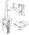
- FIG. 1 illustrates an isometric view of the unitary paint brush, handle, base and bristle holder.
- the main component of the unitary paint brush comprises a handle 7 which melds smoothly with the plastic body 1, which is typically formed from injection molded polypropylene or polyethylene.
- the body 1 has on each longitudinal side thereof, at the end opposite the handle 7, a pair of hinged bristle compressing flaps 2.
- Finger grips 3 are located on each narrow lateral side of the body 1.
- the hinged flaps 2 are held in place by rotatable springs 5 which, in a closed position, hold the flaps 2 against the bristles 6, and which, when swung to the side, release the flaps 2 so that they can be pivoted outwardly away from the bristles 6.
- Each spring 5 has a U-shape, with curled ends.
- the hinge line for the flap 2 is indicated by hinge line 19.
- the free edges of the two hinged flaps 2 are reinforced with respective stainless steel U clips 8, which provide dimensional stability to the edge of the flap 2, thereby resisting bending when the flaps 2 are folded against the bristles 6.
- Grooves 10 are formed at each end of the flap 2, in line with the hinged edge 19. These grooves 10 accommodate the transverse part of the rotatable springs 5. End flaps 9 are located below the finger grips 3, on the narrow lateral sides opposite the handle 7.
- FIG. 1 Also seen in Figure 1 are a breathing hole 28, at the end of the handle 7, removed from the body 1.
- the hole 28 permits moisture to escape from the interior of the handle 7 when the handle 7 and body 1 are being molded.
- An ergonomic finger groove 29 is formed in the handle 7, in the region where it meets with the body 1. This groove 29 improves grippability of the handle 7.
- the body 1, on the narrow lateral sides, in the region where the body 1 melds with the handle 7, includes a pair of heart valves 27. These valves are used for glue injection when the bristles 6 are being installed in the body 1.
- Figure 2 illustrates an isometric side view of the body 1 and flap 2 of the unitary paint brush and bristle holder.
- flap 2 has been pivoted upwardly away from end flap 9.
- the groove 10 for the lateral part of spring 5 is visible clearly in Figure 2.
- the flap 2 pivots away from the end flap 9, and the bristles (not shown), along hinge line 19.
- female wedge opening 12 is also seen in Figure 2 adapted to receive a mid-section 11 (not shown), which will be discussed later.
- FIG 3 illustrates an isometric detailed view of the corner of the flap 2, hinge line 19 and body 1 combination.
- the free end of the flap 2, at the edge away from the hinge line 19, has formed therein along its length a clip depression 17, which is adapted to receive the stainless steel reinforcing U clip 8 (see Figure 1).
- the corner of the flap 2 is recessed to form depression 4, which is adapted to receive spring 5, when the spring 5 is rotated to a closed position whereby the flap 2 is pressed against the bristles (not shown).
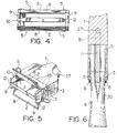
- FIG 4 illustrates an end view of the unitary paint brush and bristle holder, without the bristles.
- the pair of stainless steel reinforcing U clips 8 extend along each longitudinal side of the flaps 2. As seen in Figure 4, the flaps and clips 8 are in a closed position, with the four rotatable springs 5 moved to respective closed positions. End flaps 9 extend along the edge of each narrow lateral side of the bristle holder.
- Mid-section 11 is formed to have at each end a pair of wedge-shaped ends 12, which fit within the wedge-shaped opening in the end of respective end flaps 9. While not shown, the bristles 6 are mounted in two groups in the spaces formed between mid-section 11 and the adjacent parallel flaps 2 and clips 8.
- Figure 5 illustrates an isometric view of the end of the unitary paint brush and bristle holder 1, before the bristles are installed in the two spaces formed between the pair of flaps 2, part of the body 1, and the mid-section 11.
- the two springs 5 have been moved to respective open positions, and the pair of flaps 2 with U clips 8 are hinged away from the respective end flaps 9 along hinge line 19.
- Mid-section 11 can be seen mounted between end flaps 9, and held in place by respective wedges 12.
- Finger grips 3 are also shown on the one visible narrow lateral side of the body 1.
- the unitary paint brush and bristle holder is adapted to receive the insertion of two bunches of bristles 6 (not shown) in the respective openings existing between the central mid-section 11 and the exterior adjacent flaps 2, and the interior of body 1, formed on either side of mid-section 11.
- the bristles are glued in place by injecting glue through heart valve 27 (see also Figure 1).
- a corresponding heart valve 27 is located on the opposite narrow side of body 1, although it is not visible in Figure 5.
- a series of openings 15 are formed in the edge of the midsection 11 adjacent the body 1. These openings 15 permit glue to pass from one side of mid-section 11 to the other side of mid-section 11, thereby ensuring consistent and uniform gluing of the bristles in place in the interior of the body 1.
- Figure 6 illustrates a side partial section view of the unitary paint brush body and bristle holder, with the two groups of bristles 6 installed within the interior of the body 1, between the pair of flaps 2, and clips 8, and the central mid-section 11.
- the bristle base 21 is glued in place by injecting glue through heart valve 27, which communicates with bristle base 21 by interior channel 31.
- the springs 5 are in a closed position whereby flaps 2, and the respective U clips 8, are pressed against the exterior sides of the two groups of bristles 6 to compress them tightly together against mid-section 11.
- Figure 6 also illustrates the cavity 20, which is formed in the bristles 6 by the end of mid-section 11. This cavity 20 is useful for enabling the paint brush to hold more paint than would be the case if cavity 20 were absent. This reduces the frequency of dipping the brush in a paint can.
- FIG 7 illustrates a detailed front view of the construction of the mid-section 11.
- the mid-section is generally rectangular in construction, and planar.
- a pair of wedge inserts 12 are formed at the two bottom corners. These two wedges 12 fit respectively within the wedge openings which are formed in the two end flaps 9 of the body 1 (see Figure 1).
- a series of striations 13 are formed along the edge of mid-section 11, between the pair of wedges 12. These striations 13 help hold the adjacent bristles 6 (not shown) and prevent the bristles from wiggling back and forth when the brush is being used.
- a narrow bar 32 passes across the open edges of the openings 15. This bar 32 serves to grip the glue after it hardens, thereby deterring the removal of mid-section 11, once glue is in place. If bar 32 were not present, and the openings 15 were thus open-ended, it is possible that with use the mid-section 11 could be pulled away from the glue which holds the bristle base 21 in place within the interior of the paint brush body 1.
- Figure 8 illustrates an end view of the mid-section 11, and in particular, the construction of the pair of wedges 12 at each end.
- the locations where the pair of wedges 12 join with the main body of the mid-section 11 are narrow to correspond with the tapered shape of the wedge openings formed in end flaps 9. This construction prevents the pair of end flaps 9 from flaring away from mid-section 11, when pressure is applied to the paint brush bristles.
- Figure 9 illustrates a detailed end view of the mid-section 11 and the wedge 12.
- Figure 10 illustrates a front partial section view of a portion of the paint brush body 1 and end flap 9, equipped with a hook 33.
- This hook 33 is optional and fits in opening 30, formed in body 1 (see also Figure 1).
- the hook 33 enables the paint brush to be conveniently hooked onto the edge of a paint can. Often, it is difficult to find a location to lay down a wet paint brush. Laying the paint brush along the edge of the top of a can sometimes causes an accident where the brush either falls into the interior of the can, or gets knocked off and falls onto the floor, thereby putting unwanted paint on the floor.
- Figure 11 illustrates an isometric view of an alternative embodiment of brush.
- the mid-section 11 is optional. It does not necessarily have to be present in the unitary paint brush and bristle holder. If the mid-section 11 is absent, wedges can be formed in the ends of the flaps 2, which are adapted to mate with corresponding wedge-shaped recesses in the sides of end flaps 9, thereby enabling the flaps 2 to unite with the end flaps 9, when the springs 5 are moved into place. This configuration is illustrated in Figure 11.
- a major advantage of the unitary paint brush is that it can be quickly and economically injection molded in one piece, thereby eliminating the need to have a separate ferrule, and a separate handle.
- the unitary brush is therefore more economical to produce in mass quantities.
- Another major advantage is that when the pair of flaps 2 are forced against the bristles 6 by moving springs 5 into a closed position, the solid paint particles in the paint emulsion coating the bristles 6 are prevented from migrating along the bristles past the reinforcing U clip edges 8. While the liquid medium of the paint emulsion may migrate by capillary action along the bristles 8, and past the pair of flaps 2, the solids in the emulsion are effectively stopped at the point of pressure under the edge of the pair of U clips 8. A liquid solid separation therefore takes place in the region of each flap 2 and U clip 8.
- the springs 5 When it is time to clean the paint brush, the springs 5 are rotated into open positions, the pair of hinged flaps 2 are pivoted away from the bristles 8, and bristles which have not been coated with solid paint are exposed for cleaning with a paint solvent.
- the interrupted solids are openly exposed on the bristles 6, at an intermediate point, and are not accumulated against the base of the bristles.
- the solvent can be either a petroleum distillate, which is normally used for cleaning oil-based paint brushes, or water, which is used to remove water soluble latex-based paints.
Landscapes
- Brushes (AREA)
- Coating Apparatus (AREA)
- Polishing Bodies And Polishing Tools (AREA)
Claims (14)
- Pinsel, umfassend einen Griff, einen Borstenhalter und Borsten, gekennzeichnet durch:(a) ein Pinselgehäuse (1) und einen Griff (7) aus einem Stück, die als eine Einheit aus Kunststoff geformt sind, wobei in einem Ende des Gehäuses (1) gegenüber dem Griff ein Hohlraum gebildet ist, der so ausgestaltet ist, daß er ein Ende einer Gruppe von Borsten (6) aufnimmt;(b) ein Paar gelenkig verbundener lösbarer Elemente (2, 2), die gleichzeitig mit dem Gehäuse (1) und dem Griff (7) aus Kunststoff geformt werden und auf gegenüberliegenden Seiten des Gehäuses (1) befestigt sind und über den Hohlraum vorstehen, wobei die lösbaren Elemente (2, 2) jeweils gelenkig an dem Gehäuse (1) über jeweilige Gelenklinien (19, 19) angebracht sind und eng an den Borsten (6) anliegen können, wenn sie in eine erste geschlossene Position gebracht werden, und von den Borsten (6) entfernt werden können, wenn sie in eine zweite offene Position gebracht werden;(c) bewegliche Befestigungsmittel (5) zum Befestigen der gelenkig verbundenen lösbaren Elemente (2, 2) in einer ersten Position gegen die Borsten und zum Lösen der gelenkig verbundenen lösebaren Elemente (2, 2) zum Bewegen in eine zweite offene Position; und(d) eine Gruppe von Borsten (6), die an einem Ende zusammengeklebt sind, das im Hohlraum des Halters (1) und zwischen dem Paar gelenkig verbundener lösbarer Elemente (2, 2) gehalten wird.
- Pinsel nach Anspruch 1, bei dem die beweglichen Befestigungsmittel Metallfedern (5) sind.
- Pinsel nach Anspruch 1 oder Anspruch 2, bei dem das Paar gelenkig verbundener lösbarer Elemente (2, 2) längliche ebene Klappen sind, die jeweils über jede Seite des Gehäuses angrenzend an den Hohlraum gelenkig verbunden sind, wobei die Klappen Vertiefungen (4) in ihren freien Ecken aufweisen, die für den Eingriff mit den beweglichen Befestigungsmitteln (5) vorgesehen sind.
- Pinsel nach Anspruch 3, bei dem die von den Seiten der Klappen, die an das Gehäuse (1) gelenkig verbunden sind, weggelegenen freien Kanten der Klappen (2, 2) Verstärkungsklemmen (8, 8) aufweisen, die über die Vertiefung (17) daran befestigt sind.
- Pinsel nach Anspruch 4, bei dem das bewegliche Befestigungsmittel Federn (5, 5) sind, die relativ zu dem Paar Klappen (2, 2) schwenken und die, wenn sie in eine erste Position geschwenkt werden, die Klappen gegen die Borsten (6) schließen, und wenn sie in eine zweite offene Position geschwenkt werden, ermöglichen, daß die Klappen (2, 2) von den Borsten (6) wegbewegt werden.
- Pinsel nach Anspruch 5, bei dem die jeweiligen Federn (5, 5) U-förmig sind und eine Basis und zwei aufrechte Arme aufweisen, wobei die Arme eine umgekehrte U-Form haben.
- Pinsel nach einem der Ansprüche 1 bis 6, bei dem ein entfernbarer Borstentrenner (11) in dem Hohlraum zwischen dem Paar gelenkig verbundener lösbarer Elemente (2, 2) plaziert ist.
- Pinsel nach Anspruch 7, bei dem das in den Hohlraum eingreifende Ende der Borsten (6) im Inneren des Hohlraums durch Injizieren von Klebstoff durch eine Öffnung (27) und einen Kanal (31) festgeklebt wird, der durch das Pinselgehäuse (1) in das Innere des Hohlraums dringt, und der Trenner (11) wenigstens eine Öffnung (15) an dem zum Gehäuse (1) angrenzenden Ende aufweist, um den Klebstoff durch eine Seite des Trenners (11) zur anderen laufen zu lassen.
- Pinsel nach Anspruch 7 oder Anspruch 8, bei dem der entfernbare Borstentrenner (11) durch Keile (12) an Endwänden (9) des Hohlraums zwischen den jeweiligen gelenkig verbundenen losbaren Elementen (2, 2) befestigt ist.
- Pinsel nach einem der Ansprüche 7 bis 9, bei dem der entfernbare Borstentrenner (11) eine Reihe von Öffnungen (15) über eine seiner Seiten aufweist, wobei die genannten Öffnungen (15) so ausgestaltet sind, daß sie Klebstoff von einer Seite des Borstentrenners (11) zur gegenüberliegenden Seite des Borstentrenners (11) laufen lassen, und ein Stab (32) die Öffnungen (15) einschließt und den Trenner (11) und die Borsten (6) im Innern des Hohlraums festhält.
- Pinsel nach einem der Ansprüche 7 bis 10, bei dem der Trenner auf jeder seiner breiten Flächen Rillen (13) aufweist, die in die Borsten eingreifen und diese festhalten.
- Pinsel nach Anspruch 3 oder Anspruch 4, bei dem die gelenkig verbundenen Seitenklappen (2, 2) Verbindungsstücke (38) aufweisen, die es ermöglichen, daß die Seitenklappen (2, 2) mit Endklappen (9) verbunden werden können, die zwischen den Seitenklappen (2, 2) geformt sind, wenn die Seitenklappen in einer geschlossenen Position sind.
- Pinsel nach einem der Ansprüche 1 bis 12, bei dem ein Haken (33) im Gehäuse (1) des Pinsels befestigt ist, wobei der Haken so ausgestaltet ist, daß der Pinsel an eine Farbdose gehakt werden kann.
- Pinsel nach einem der Ansprüche 1 bis 13, bei dem das Gehäuse (1) und der Griff (7) eine Öffnung (28) aufweisen, die von dem Ende des Griffs (7), das dem Gehäuse (1) gegenüberliegt, zu dem Hohlraum im Gehäuse verläuft.
Applications Claiming Priority (3)
| Application Number | Priority Date | Filing Date | Title |
|---|---|---|---|
| US07/968,771 US5289606A (en) | 1992-10-30 | 1992-10-30 | Unitary paint brush and bristle holder |
| PCT/CA1993/000440 WO1994009680A1 (en) | 1992-10-30 | 1993-10-19 | Unitary paint brush and bristle holder |
| US968771 | 1997-11-10 |
Publications (2)
| Publication Number | Publication Date |
|---|---|
| EP0768833A1 EP0768833A1 (de) | 1997-04-23 |
| EP0768833B1 true EP0768833B1 (de) | 1998-06-03 |
Family
ID=25514755
Family Applications (1)
| Application Number | Title | Priority Date | Filing Date |
|---|---|---|---|
| EP93922875A Expired - Lifetime EP0768833B1 (de) | 1992-10-30 | 1993-10-19 | Einteiliger pinsel- und borstenhalter |
Country Status (7)
| Country | Link |
|---|---|
| US (1) | US5289606A (de) |
| EP (1) | EP0768833B1 (de) |
| JP (1) | JPH08504619A (de) |
| AU (1) | AU677793B2 (de) |
| CA (1) | CA2147871C (de) |
| DE (1) | DE69318990T2 (de) |
| WO (1) | WO1994009680A1 (de) |
Cited By (1)
| Publication number | Priority date | Publication date | Assignee | Title |
|---|---|---|---|---|
| DE202016101789U1 (de) | 2016-04-05 | 2017-07-06 | M.A.C.'s Holding Gmbh | Pinselgriff |
Families Citing this family (12)
| Publication number | Priority date | Publication date | Assignee | Title |
|---|---|---|---|---|
| US5435037A (en) * | 1993-12-22 | 1995-07-25 | Terry R. Douglas | Paint brush with replaceable bristle pack |
| US5678276A (en) * | 1992-10-30 | 1997-10-21 | Ledingham; Blake A. | Paint brush with bristle clamping panels |
| CA2154908C (en) * | 1995-07-28 | 2000-06-06 | David J. Waldner | Broom cap |
| US6049937A (en) * | 1998-03-26 | 2000-04-18 | Rubbermaid Incorporated | Wire retention mechanism for a broom |
| US6035481A (en) | 1998-06-01 | 2000-03-14 | Kwick Clean And Green Ltd. | Paint brush with hinged inverted bristle clamping panel, removable bristle pack and panel hinge yield member |
| CA2280332C (en) | 1999-08-13 | 2005-03-15 | Kwick Clean And Green Ltd. | Internal ferrule for paint brush with bristle clamping panel and removable bristle pack |
| US6510578B1 (en) | 2000-04-21 | 2003-01-28 | William F. Cyr | Brush having removable bristle pack |
| US20060218737A1 (en) * | 2005-04-05 | 2006-10-05 | Minelli S.P.A. | Handle for angular brush having an holding tenon for the glue, the relative brush and method for its construction |
| US7805797B2 (en) * | 2006-09-11 | 2010-10-05 | Douglas Terry R | Paint brush with cantilevered clamping panel and removable bristle pack |
| DE102008019111A1 (de) * | 2008-04-16 | 2009-10-22 | Firma G.B. Boucherie N.V. | Pinsel |
| US8402592B2 (en) * | 2008-08-22 | 2013-03-26 | The Wooster Brush Company | Flex brush apparatus and method |
| US20170203609A1 (en) * | 2016-01-20 | 2017-07-20 | Derek R. Haskins | Paintbrush with hanging means |
Family Cites Families (26)
| Publication number | Priority date | Publication date | Assignee | Title |
|---|---|---|---|---|
| BE497801A (de) * | ||||
| US540824A (en) * | 1895-06-11 | Brooivi-head | ||
| US719227A (en) * | 1902-01-04 | 1903-01-27 | Lenson Johnson | Brush. |
| US871494A (en) * | 1906-07-18 | 1907-11-19 | Walter D Foss | Brush. |
| US964707A (en) * | 1909-12-18 | 1910-07-19 | Herbert Henry Stevens | Brush. |
| US999307A (en) * | 1910-11-14 | 1911-08-01 | James S Holcombe | Broom. |
| US1198167A (en) * | 1915-01-05 | 1916-09-12 | Charles E Stoltz | Broom. |
| CA182819A (en) * | 1917-09-19 | 1918-03-21 | Charles Ephraim Hecht | Brush holder |
| FR714282A (fr) * | 1930-07-08 | 1931-11-10 | Pinceau | |
| US2326879A (en) * | 1940-11-22 | 1943-08-17 | Sebastian P Neuhausen | Brush |
| US2419899A (en) * | 1943-12-13 | 1947-04-29 | Kantor Israel | Paint brush |
| US2785427A (en) * | 1952-02-15 | 1957-03-19 | Irvin F Bury | Paint brushes and the like |
| US2912709A (en) * | 1956-11-14 | 1959-11-17 | Roy H Carlson | Brush with detachable bristles |
| US2900654A (en) * | 1957-11-06 | 1959-08-25 | Koltvedt Abel | Brush or the like having removable head |
| US2948910A (en) * | 1958-10-27 | 1960-08-16 | Louis J Hulla | No drip brush attachment |
| US3155998A (en) * | 1960-02-02 | 1964-11-10 | H V Hardman Company Inc | Brush structure |
| US3090063A (en) * | 1962-02-01 | 1963-05-21 | Wooster Brush Co | Paint brushes |
| US3131419A (en) * | 1962-10-18 | 1964-05-05 | Peter S Vosbikian | Paint applicators |
| US3263259A (en) * | 1964-06-15 | 1966-08-02 | Baker Brush Co Inc | Paint brush |
| US4129918A (en) * | 1977-08-29 | 1978-12-19 | Robert Lee | Adjustable sleeve for artists paint brushes |
| US4237579A (en) * | 1978-09-15 | 1980-12-09 | Salmon Jonathan H | Graining brush |
| US4339837A (en) * | 1980-10-27 | 1982-07-20 | Christiaan Reeberg | Paint brush accessory |
| GB2096888B (en) * | 1981-04-21 | 1985-07-03 | Black & Decker | Improvements in or relating to brushes for applying liquids to surfaces |
| US5044038A (en) * | 1990-01-16 | 1991-09-03 | Zvonko Matkovic | Foldable paint brush hook assembly |
| US4887327A (en) * | 1987-08-14 | 1989-12-19 | Angelo Meimeteas | Paint brush ferrule cover |
| WO1992013472A1 (en) * | 1991-02-01 | 1992-08-20 | Blake Andrew Ledingham | Paint brush bristle holder |
-
1992
- 1992-10-30 US US07/968,771 patent/US5289606A/en not_active Expired - Fee Related
-
1993
- 1993-10-19 DE DE69318990T patent/DE69318990T2/de not_active Expired - Fee Related
- 1993-10-19 AU AU51737/93A patent/AU677793B2/en not_active Ceased
- 1993-10-19 JP JP6510495A patent/JPH08504619A/ja active Pending
- 1993-10-19 EP EP93922875A patent/EP0768833B1/de not_active Expired - Lifetime
- 1993-10-19 WO PCT/CA1993/000440 patent/WO1994009680A1/en not_active Ceased
- 1993-10-19 CA CA002147871A patent/CA2147871C/en not_active Expired - Fee Related
Cited By (1)
| Publication number | Priority date | Publication date | Assignee | Title |
|---|---|---|---|---|
| DE202016101789U1 (de) | 2016-04-05 | 2017-07-06 | M.A.C.'s Holding Gmbh | Pinselgriff |
Also Published As
| Publication number | Publication date |
|---|---|
| JPH08504619A (ja) | 1996-05-21 |
| US5289606A (en) | 1994-03-01 |
| WO1994009680A1 (en) | 1994-05-11 |
| AU5173793A (en) | 1994-05-24 |
| AU677793B2 (en) | 1997-05-08 |
| DE69318990T2 (de) | 1998-12-10 |
| CA2147871C (en) | 1998-12-15 |
| EP0768833A1 (de) | 1997-04-23 |
| CA2147871A1 (en) | 1994-05-11 |
| DE69318990D1 (de) | 1998-07-09 |
Similar Documents
| Publication | Publication Date | Title |
|---|---|---|
| EP0735834B1 (de) | Pinsel mit auswechselbarem borstensatz | |
| CA2217512C (en) | Paint brush with bristle clamping panels | |
| US5289606A (en) | Unitary paint brush and bristle holder | |
| CA2280332C (en) | Internal ferrule for paint brush with bristle clamping panel and removable bristle pack | |
| EP1082033B1 (de) | Pinsel mit einem schwenkbaren, invertierten borstenklemmhalter, einem austauschbaren borstenträger und einem elastischen paneelscharnierelement | |
| US5315733A (en) | Paint brush bristle clamp | |
| US7805797B2 (en) | Paint brush with cantilevered clamping panel and removable bristle pack | |
| EP0569352B1 (de) | Borstenhalter für einen farbpinsel | |
| CA2153741C (en) | Recyclable one-material paint brush with hinged clamping panel for removable bristle pack | |
| CA2100249C (en) | Paint brush bristle holder | |
| WO1996017536A1 (en) | Paint brush with bristle clamping panel and removable bristle pack | |
| US6954964B2 (en) | Paint brush scrubber |
Legal Events
| Date | Code | Title | Description |
|---|---|---|---|
| PUAI | Public reference made under article 153(3) epc to a published international application that has entered the european phase |
Free format text: ORIGINAL CODE: 0009012 |
|
| 17P | Request for examination filed |
Effective date: 19950524 |
|
| AK | Designated contracting states |
Kind code of ref document: A1 Designated state(s): DE GB SE |
|
| GRAG | Despatch of communication of intention to grant |
Free format text: ORIGINAL CODE: EPIDOS AGRA |
|
| 17Q | First examination report despatched |
Effective date: 19970923 |
|
| GRAG | Despatch of communication of intention to grant |
Free format text: ORIGINAL CODE: EPIDOS AGRA |
|
| GRAH | Despatch of communication of intention to grant a patent |
Free format text: ORIGINAL CODE: EPIDOS IGRA |
|
| GRAH | Despatch of communication of intention to grant a patent |
Free format text: ORIGINAL CODE: EPIDOS IGRA |
|
| GRAA | (expected) grant |
Free format text: ORIGINAL CODE: 0009210 |
|
| AK | Designated contracting states |
Kind code of ref document: B1 Designated state(s): DE GB SE |
|
| REF | Corresponds to: |
Ref document number: 69318990 Country of ref document: DE Date of ref document: 19980709 |
|
| PLBE | No opposition filed within time limit |
Free format text: ORIGINAL CODE: 0009261 |
|
| STAA | Information on the status of an ep patent application or granted ep patent |
Free format text: STATUS: NO OPPOSITION FILED WITHIN TIME LIMIT |
|
| 26N | No opposition filed | ||
| PGFP | Annual fee paid to national office [announced via postgrant information from national office to epo] |
Ref country code: SE Payment date: 20011003 Year of fee payment: 9 |
|
| REG | Reference to a national code |
Ref country code: GB Ref legal event code: IF02 |
|
| PG25 | Lapsed in a contracting state [announced via postgrant information from national office to epo] |
Ref country code: SE Free format text: LAPSE BECAUSE OF NON-PAYMENT OF DUE FEES Effective date: 20021020 |
|
| PGFP | Annual fee paid to national office [announced via postgrant information from national office to epo] |
Ref country code: GB Payment date: 20021030 Year of fee payment: 10 |
|
| PGFP | Annual fee paid to national office [announced via postgrant information from national office to epo] |
Ref country code: DE Payment date: 20021111 Year of fee payment: 10 |
|
| EUG | Se: european patent has lapsed | ||
| PG25 | Lapsed in a contracting state [announced via postgrant information from national office to epo] |
Ref country code: GB Free format text: LAPSE BECAUSE OF NON-PAYMENT OF DUE FEES Effective date: 20031019 |
|
| PG25 | Lapsed in a contracting state [announced via postgrant information from national office to epo] |
Ref country code: DE Free format text: LAPSE BECAUSE OF NON-PAYMENT OF DUE FEES Effective date: 20040501 |
|
| GBPC | Gb: european patent ceased through non-payment of renewal fee |
Effective date: 20031019 |