EP0768102B1 - Embase de fixation de ski réglable longitudinalement - Google Patents
Embase de fixation de ski réglable longitudinalement Download PDFInfo
- Publication number
- EP0768102B1 EP0768102B1 EP96810662A EP96810662A EP0768102B1 EP 0768102 B1 EP0768102 B1 EP 0768102B1 EP 96810662 A EP96810662 A EP 96810662A EP 96810662 A EP96810662 A EP 96810662A EP 0768102 B1 EP0768102 B1 EP 0768102B1
- Authority
- EP
- European Patent Office
- Prior art keywords
- plate
- slider
- lever
- release lever
- fitted
- Prior art date
- Legal status (The legal status is an assumption and is not a legal conclusion. Google has not performed a legal analysis and makes no representation as to the accuracy of the status listed.)
- Expired - Lifetime
Links
Images


Classifications
-
- A—HUMAN NECESSITIES
- A63—SPORTS; GAMES; AMUSEMENTS
- A63C—SKATES; SKIS; ROLLER SKATES; DESIGN OR LAYOUT OF COURTS, RINKS OR THE LIKE
- A63C9/00—Ski bindings
- A63C9/005—Ski bindings with means for adjusting the position of a shoe holder or of the complete binding relative to the ski
Definitions
- the present invention relates to a mounting base ski adjustable longitudinally including a slide intended to be fixed to a ski and having a row of notches parallel to the axis of the slide and a plate mounted sliding on the slide and carrying a lock engaged in at least one notch of the slide so as to immobilize the plate on the slide, as well as a mounted release lever pivoting on the plate around a perpendicular axis to the plate, the lock being made up of one piece separate from the lever, slidably mounted transversely to the plate.
- Such bases are used to equip skis demonstration and high-end rental in the purpose of allowing the distance between the front binding and the rear binding in size of the user's shoe while retaining the center of the boot at the same point on the ski. In this effect it is necessary to move the fixation before the rear fixation during a change of shoe size.
- the invention aims to remove the backlash in its slide without auxiliary elastic body and without the need to give lateral play to the lock.
- the base according to the invention is characterized in that the lock is engaged by the action of a spring in the notch of the slide and in that said base further includes a movable element for removing clearance between the plate and the slide, this element mobile being movable by action on said lever unlocking.
- the element of game removal consists of a sliding shoe actuated by the release lever by means of a knee joint.
- the removal of the game is done by means of a cam vertically spreading the plate and slide from each other.
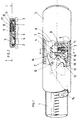
- Figure 1 is a plan view of a base according to a first form of execution.
- Figure 2 is a sectional view along II-II of the figure 1.
- Figures 3, 4 and 5 illustrate, by means of a variant of execution, the operation of the first mode of execution.
- Figure 6 is a plan view of a second form of execution in which the top plate has been cut to reveal the locking mechanism and game removal.
- Figure 7 is a sectional view along VII-VII of the figure 6.
- Figure 8 is a partial view of an alternative embodiment of the second embodiment.
- the base shown in Figures 1 and 2 includes a slide 1 consisting of a cut metal plate and folded in such a way that over part of its length edges 2 and 3 are raised so as to form the slide itself, as shown in the Figure 2.
- a row of trapezoidal notches 4 On the slide 2 is mounted a plate 5 on which just attach the ski binding, in the example considered, a front stop.
- Plate 5 is a molded plate with housings and guides on its underside.
- the plate 5 has been partially torn off so as to reveal the locking mechanisms and backlash. Locking is assured by a lock 6 consisting of a sliding mounted part transversely in a housing on the underside of plate 5.
- This lock 6 is provided with two trapezoid teeth 7 engaging between at least two notches 4 under the thrust of a spring 8 penetrating laterally in a cutout 9 of the plate 5 and working in compression between latch 6 and edge 10 of the cutout 9.
- the lock 6 has an arm 11 passing through spring 8.
- a lever 13 On the underside of the plate 5, is further mounted, pivoting around an axis 12, a lever 13 provided on one side of a spout 14 and on the other end of a handle 15 accessible for operating the lever 13.
- the lever 13 is also kinematically connected to a shoe 16 slidably mounted obliquely in a groove provided in the underside of the plate 5 and opening on the side of the plate 5 opposite the latch 6, at the level the vertical edge 17 of the slide 1 (FIG. 2), by a slightly curved link 18, articulated on the lever 13 around an axis 19 and constituting a toggle with lever 13.
- Figure 1 shows the base in the locked position and game removed.
- the axis 19 is slightly to the right of the straight line connecting axis 12 to the articulation of the link 18 on the shoe 16.
- the rod 18 is slightly bent elastically by so that shoe 16 is pressed against the side of slide 1, so that plate 5 does not cannot move sideways on slide 1. This blocking also removes the game vertical.
- the lever 13 is pivoted clockwise. During this pivoting, one must first of all exert sufficient force to pass the hard point of the kneepad. The beak 14 comes next push back the latch 6 so as to release its teeth notches 4. As soon as the lever 13 is released, the spring 8 pushes the lock again in the notches 4. To remove the backlash, the lever is then pushed back 13 in the position shown in the drawing.
- a lock 20 sliding mounted transversely and provided with two engaging teeth in a toothing 21 of the slide under the thrust a spring 22.
- This lock has a spout 23 and a heel 24 close to the teeth.
- An unlocking lever 25 is articulated around an axis 26 and it is connected to a shoe 27, similar to shoe 16, by a link 28.
- FIG. 3 represents the device in the unlocked position, a force being exerted on the lever 25 as indicated by the arrow. In this position, a beak 29 of lever 25 pushes back lock 20 by its beak 23 by compressing the spring 22.
- Leverage 25 takes a middle position (figure 4).
- the game can be removed significantly different, as illustrated by the second form shown in Figures 6 and 7.
- a slide 1 identical to the first embodiment.
- a coated metal plate 31 here a trim 32 of synthetic material.
- a lock 33 is pushed into the notches 4 of the slide by a spring 34 working in flexion between a stud 35 of the lock 33 and a pad 36 of the plate 31.
- the lock 33 can be actuated by a lever 37 mounted pivoting around an axis 38 and provided with a spout 39 engaging in a V-shaped cutout of the lock 33.
- This lock is therefore practically articulated at the end of lever 37.
- the lever 37 is crossed by an axis 40 extending parallel to plate 31 and provided, at one of its ends, of a pallet 41 and, at its other end, a cam 43 formed or attached to the axis 40.
- the pallet 41 is folded down in a groove 42 provided for this purpose in the upper face of the plate 32 and the cam 43 is oriented perpendicular to the plate 31, as shown in phantom in 43 'in Figure 7, such that it spreads the plate 31 from the slide 1.
- This has the effect of strongly pressing the edges 31a of the plate 31 against the edges 1a of the slide 1.
- This metal-to-metal contact immobilizes by rubbing the plate 31 on the slide, removing all play, both lateral and vertical.
- Pallet 41 could be replaced by any other handle for driving the entire lever unlocking in rotation and axis 40 in rotation.
Landscapes
- Footwear And Its Accessory, Manufacturing Method And Apparatuses (AREA)
- Joining Of Building Structures In Genera (AREA)
- Aiming, Guidance, Guns With A Light Source, Armor, Camouflage, And Targets (AREA)
- Artificial Filaments (AREA)
Description
Claims (6)
- Embase de fixation de ski réglable longitudinalement comprenant une glissière (1) destinée à être fixée au ski et présentant une rangée de crans (4; 21) parallèle à l'axe de la glissière et une plaque (5; 31) montée coulissante sur la glissière et portant un verrou (6; 20; 33) engagé dans au moins un cran de la glissière de manière à immobiliser la plaque sur la glissière, ainsi qu'un levier de déverrouillage (13; 25; 37) monté pivotant sur la plaque autour d'un axe perpendiculaire à la plaque, le verrou (6; 20; 33) étant constitué d'une pièce distincte du levier, montée coulissante transversalement à la plaque, caractérisée en ce que le verrou est engagé sous l'action d'un ressort dans le cran de la glissière et en ce que ladite embase comprend en outre un élément mobile (16; 27; 43) de suppression de jeu entre la plaque et la glissière, cet élément mobile étant déplaçable par une action sur ledit levier de déverrouillage.
- Embase selon la revendication 1, caractérisée en ce que l'élément de suppression de jeu est constitué d'un sabot (16; 27) monté coulissant dans ou sous ladite plaque au niveau du côté intérieur de la glissière opposé aux crans et en ce que le levier (13; 25) est relié cinématiquement à ce sabot par une biellette (18; 28) formant genouillère avec le levier de déverrouillage, genouillère telle que le sabot est pressé contre le côté de la glissière et maintenu dans cet état lorsque le levier de déverrouillage est poussé à force dans une position particulière additionnelle opposée à sa position de déverrouillage.
- Embase selon la revendication 2, caractérisée en ce que la biellette (18) est courbe.
- Embase selon la revendication 2, caractérisée en ce que le levier de déverrouillage (25) vient au moins approximativement en contact avec une portée (24) du verrou dans la position de suppression de jeu, de manière à verrouiller le verrou.
- Embase selon la revendication 1, caractérisée en ce que le levier de déverrouillage est en deux parties (37, 40), l'une de ces parties étant constituée d'un axe (40) monté rotativement, parallèlement au plan de la plaque (31), dans l'autre partie et servant de bras d'actionnement du levier, l'élément de suppression de jeu étant constitué d'une came (43) montée ou formée sur ledit axe, cet axe étant muni d'une poignée servant, d'une part, à entraíner le levier de déverrouillage et, d'autre part, à entraíner la came en rotation pour l'amener dans une position dans laquelle elle écarte verticalement la plaque et la glissière l'une de l'autre de telle manière que la plaque est bloquée dans la glissière.
- Embase selon la revendication 5, caractérisée en ce que la glissière et la plaque présentent des bords obliques (1'a, 31'a) venant se plaquer l'un sur l'autre en position bloquée.
Applications Claiming Priority (2)
| Application Number | Priority Date | Filing Date | Title |
|---|---|---|---|
| FR9512112 | 1995-10-10 | ||
| FR9512112A FR2739572B1 (fr) | 1995-10-10 | 1995-10-10 | Embase de fixation de ski reglable longitudinalement |
Publications (2)
| Publication Number | Publication Date |
|---|---|
| EP0768102A1 EP0768102A1 (fr) | 1997-04-16 |
| EP0768102B1 true EP0768102B1 (fr) | 2000-01-26 |
Family
ID=9483566
Family Applications (1)
| Application Number | Title | Priority Date | Filing Date |
|---|---|---|---|
| EP96810662A Expired - Lifetime EP0768102B1 (fr) | 1995-10-10 | 1996-10-04 | Embase de fixation de ski réglable longitudinalement |
Country Status (5)
| Country | Link |
|---|---|
| US (1) | US5794962A (fr) |
| EP (1) | EP0768102B1 (fr) |
| AT (1) | ATE189129T1 (fr) |
| DE (1) | DE69606372T2 (fr) |
| FR (1) | FR2739572B1 (fr) |
Cited By (1)
| Publication number | Priority date | Publication date | Assignee | Title |
|---|---|---|---|---|
| EP2484414A2 (fr) | 2011-02-04 | 2012-08-08 | MARKER Deutschland GmbH | Verrouillage d'une fixation d'une planche de glisse réglable dans le sens de la longueur |
Families Citing this family (15)
| Publication number | Priority date | Publication date | Assignee | Title |
|---|---|---|---|---|
| NO306540B1 (no) * | 1997-06-20 | 1999-11-22 | Linken Binding | Skibinding |
| FR2777473B1 (fr) | 1998-04-17 | 2000-07-13 | Salomon Sa | Dispositif interface entre un ski et des elements de retenue d'une chaussure pour regler rapidement et facilement la position longitudinale des elements de retenue avant et arriere sur un ski |
| EP1146934B1 (fr) * | 1999-08-06 | 2002-05-08 | Marker Deutschland GmbH | Dispositif de reglage en longueur d'une fixation de securite de ski |
| AT408725B (de) * | 1999-09-21 | 2002-02-25 | Atomic Austria Gmbh | Bindungshaltesystem zur schnellmontage eines vorder- und fersenbackens einer schibindung |
| FR2823681B1 (fr) * | 2001-04-24 | 2003-06-13 | Rene Bressand | Dispositif de montage/demontage rapides d'une fixation de ski sur un ski |
| FR2835759B1 (fr) | 2002-02-11 | 2004-05-14 | Look Fixations Sa | Embase de fixation de ski reglable |
| DE50206571D1 (de) * | 2002-07-05 | 2006-06-01 | Tyrolia Freizeitgeraete | Anordnung zum Längsverstellen eines Skibindungsteils |
| DE10331696A1 (de) * | 2003-07-11 | 2005-02-03 | Marker Deutschland Gmbh | Montagesystem für eine Skibindung an einem Ski |
| FR2910821B1 (fr) | 2006-12-28 | 2012-08-17 | Rossignol Sa | Fixation automatique sur une planche de glisse d'un dispositif de fixation de chaussure |
| US8011676B1 (en) * | 2009-03-19 | 2011-09-06 | Michael Keast | Snowboard assembly |
| WO2012045329A1 (fr) * | 2010-10-04 | 2012-04-12 | Madshus As | Fixation de ski |
| US9272760B2 (en) * | 2014-07-31 | 2016-03-01 | John D. Bruce | Adjustable boot for a water sport device |
| US10058763B2 (en) * | 2015-04-29 | 2018-08-28 | Bishop Bindings Llc | Telemark ski bindings systems and methods |
| NO340839B1 (no) * | 2015-11-30 | 2017-06-26 | Rottefella As | System for valgfri dynamisk posisjonering av en skibinding på en ski |
| US11229831B2 (en) | 2018-06-24 | 2022-01-25 | Bishop Bindings Llc | Telemark ski binding assembly |
Family Cites Families (14)
| Publication number | Priority date | Publication date | Assignee | Title |
|---|---|---|---|---|
| AT359898B (de) * | 1977-04-15 | 1980-12-10 | Tyrolia Freizeitgeraete | Sicherheitsskibindung |
| AT363023B (de) * | 1978-12-04 | 1981-07-10 | Linecker Josef | Langlaufbindung mit zugehoerigem schischuh |
| DE2948275A1 (de) * | 1979-11-30 | 1981-06-11 | Geze Gmbh, 7250 Leonberg | Plattensicherheitsskibindung |
| AT368394B (de) * | 1981-01-28 | 1982-10-11 | Tyrolia Freizeitgeraete | Einrichtung fuer skibindungen |
| AT370326B (de) * | 1981-04-28 | 1983-03-25 | Tyrolia Freizeitgeraete | Vorrichtung zur laengsverstellung von skibindungs- teilen |
| AT384170B (de) * | 1985-07-05 | 1987-10-12 | Tyrolia Freizeitgeraete | Verstelleinrichtung fuer skibindungen |
| US4773886A (en) * | 1985-09-09 | 1988-09-27 | Ero International Limited | Water ski binding |
| AT384950B (de) * | 1986-06-06 | 1988-01-25 | Tyrolia Freizeitgeraete | Sicherheitsskibindung |
| AT386537B (de) * | 1986-12-18 | 1988-09-12 | Tyrolia Freizeitgeraete | Verstelleinrichtung fuer skibindungen |
| FR2632200B1 (fr) * | 1988-06-03 | 1992-06-12 | Look Sa | Dispositif de reglage de la position d'une fixation de ski dans le sens longitudinal et fixation equipee d'un tel dispositif |
| FR2638654B1 (fr) * | 1988-11-08 | 1991-02-08 | Salomon Sa | Fixation de securite pour ski |
| DE58904223D1 (de) * | 1989-04-25 | 1993-06-03 | Look Sa | Sicherheitsskibindung. |
| FR2654358B1 (fr) * | 1989-11-13 | 1992-02-28 | Rossignol Sa | Fixation de securite a plaque. |
| EP0546260B1 (fr) * | 1991-11-08 | 1995-11-22 | Salomon S.A. | Dispositif de réglage de la position longitudinale d'une fixation alpine |
-
1995
- 1995-10-10 FR FR9512112A patent/FR2739572B1/fr not_active Expired - Fee Related
-
1996
- 1996-09-23 US US08/717,693 patent/US5794962A/en not_active Expired - Fee Related
- 1996-10-04 EP EP96810662A patent/EP0768102B1/fr not_active Expired - Lifetime
- 1996-10-04 AT AT96810662T patent/ATE189129T1/de not_active IP Right Cessation
- 1996-10-04 DE DE69606372T patent/DE69606372T2/de not_active Expired - Lifetime
Cited By (2)
| Publication number | Priority date | Publication date | Assignee | Title |
|---|---|---|---|---|
| EP2484414A2 (fr) | 2011-02-04 | 2012-08-08 | MARKER Deutschland GmbH | Verrouillage d'une fixation d'une planche de glisse réglable dans le sens de la longueur |
| DE102011003662A1 (de) | 2011-02-04 | 2012-08-09 | Marker Deutschland Gmbh | Verriegelung einer in Längsrichtung verstellbaren Gleitbrettbindung |
Also Published As
| Publication number | Publication date |
|---|---|
| US5794962A (en) | 1998-08-18 |
| DE69606372T2 (de) | 2000-08-10 |
| ATE189129T1 (de) | 2000-02-15 |
| EP0768102A1 (fr) | 1997-04-16 |
| DE69606372D1 (de) | 2000-03-02 |
| FR2739572B1 (fr) | 1997-12-19 |
| FR2739572A1 (fr) | 1997-04-11 |
Similar Documents
| Publication | Publication Date | Title |
|---|---|---|
| EP0097382B1 (fr) | Dispositif de fermeture d'une chaussure de sport | |
| EP0679415B1 (fr) | Dispositif de fixation d'une chaussure à un organe de glisse | |
| EP0768102A1 (fr) | Embase de fixation de ski réglable longitudinalement | |
| EP1690462A1 (fr) | Dispositif de laçage pour chaussure de sport | |
| EP0248149A1 (fr) | Chaussure de ski | |
| EP0161025B1 (fr) | Chaussure de ski | |
| FR2757782A1 (fr) | Patin a roulettes en ligne a chaussure amovible | |
| FR2753107A1 (fr) | Patin a roulettes en ligne a chaussure amovible | |
| EP0407336B1 (fr) | Chaussure de ski à chaussage par l'arrière | |
| EP0838250A1 (fr) | Dispositif de retenue d'une chaussure sur une planche de glisse | |
| EP1106218A1 (fr) | Fixation de ski de fond | |
| CH675543A5 (en) | Safety binding for ski | |
| EP0689777B1 (fr) | Chaussure de ski | |
| EP4292681A1 (fr) | Dispositif de retenue d'une chaussure sur une planche de glisse et engin de glisse comprenant un tel dispositif | |
| EP0778056B1 (fr) | Dispositif de retenue d'une chaussure à une planche de glisse telle qu'un ski ou similaire | |
| FR2745192A1 (fr) | Dispositif de retenue d'une chaussure sur une planche de glisse. | |
| FR2722420A1 (fr) | Fixation pour une planche a neige | |
| EP0983778B1 (fr) | Butée démontable pour corps coulissant de fixation de ski | |
| FR2684889A1 (fr) | Piece d'interface pour la glissiere d'un element de fixation, notamment de fixation alpine. | |
| EP1522334B1 (fr) | Elément de retenue d'une chaussure sur une planche de glisse ou de roulage | |
| EP0932434A1 (fr) | Patin a roulettes, se fixant sur la semelle d'une chaussure de marche | |
| CH656319A5 (fr) | Fixation de securite pour ski. | |
| FR2738156A1 (fr) | Dispositif de fixation et de deverrouillage automatique | |
| EP0598680A1 (fr) | Chaussure de ski | |
| FR2811904A1 (fr) | Dispositif d'orientation angulaire d'une chaussure pour planche de glisse ou de roulage |
Legal Events
| Date | Code | Title | Description |
|---|---|---|---|
| PUAI | Public reference made under article 153(3) epc to a published international application that has entered the european phase |
Free format text: ORIGINAL CODE: 0009012 |
|
| AK | Designated contracting states |
Kind code of ref document: A1 Designated state(s): AT CH DE IT LI |
|
| 17P | Request for examination filed |
Effective date: 19970315 |
|
| 17Q | First examination report despatched |
Effective date: 19980804 |
|
| GRAG | Despatch of communication of intention to grant |
Free format text: ORIGINAL CODE: EPIDOS AGRA |
|
| GRAG | Despatch of communication of intention to grant |
Free format text: ORIGINAL CODE: EPIDOS AGRA |
|
| GRAH | Despatch of communication of intention to grant a patent |
Free format text: ORIGINAL CODE: EPIDOS IGRA |
|
| GRAH | Despatch of communication of intention to grant a patent |
Free format text: ORIGINAL CODE: EPIDOS IGRA |
|
| GRAA | (expected) grant |
Free format text: ORIGINAL CODE: 0009210 |
|
| AK | Designated contracting states |
Kind code of ref document: B1 Designated state(s): AT CH DE IT LI |
|
| REF | Corresponds to: |
Ref document number: 189129 Country of ref document: AT Date of ref document: 20000215 Kind code of ref document: T |
|
| REG | Reference to a national code |
Ref country code: CH Ref legal event code: EP |
|
| REG | Reference to a national code |
Ref country code: CH Ref legal event code: NV Representative=s name: BUGNION S.A. |
|
| REF | Corresponds to: |
Ref document number: 69606372 Country of ref document: DE Date of ref document: 20000302 |
|
| ITF | It: translation for a ep patent filed | ||
| PG25 | Lapsed in a contracting state [announced via postgrant information from national office to epo] |
Ref country code: LI Free format text: LAPSE BECAUSE OF NON-PAYMENT OF DUE FEES Effective date: 20001031 Ref country code: CH Free format text: LAPSE BECAUSE OF NON-PAYMENT OF DUE FEES Effective date: 20001031 |
|
| PLBE | No opposition filed within time limit |
Free format text: ORIGINAL CODE: 0009261 |
|
| STAA | Information on the status of an ep patent application or granted ep patent |
Free format text: STATUS: NO OPPOSITION FILED WITHIN TIME LIMIT |
|
| 26N | No opposition filed | ||
| REG | Reference to a national code |
Ref country code: CH Ref legal event code: PL |
|
| PG25 | Lapsed in a contracting state [announced via postgrant information from national office to epo] |
Ref country code: IT Free format text: LAPSE BECAUSE OF NON-PAYMENT OF DUE FEES Effective date: 20051004 |
|
| PGFP | Annual fee paid to national office [announced via postgrant information from national office to epo] |
Ref country code: AT Payment date: 20081029 Year of fee payment: 13 |
|
| PG25 | Lapsed in a contracting state [announced via postgrant information from national office to epo] |
Ref country code: AT Free format text: LAPSE BECAUSE OF NON-PAYMENT OF DUE FEES Effective date: 20091004 |
|
| PGFP | Annual fee paid to national office [announced via postgrant information from national office to epo] |
Ref country code: DE Payment date: 20121029 Year of fee payment: 17 |
|
| REG | Reference to a national code |
Ref country code: DE Ref legal event code: R119 Ref document number: 69606372 Country of ref document: DE Effective date: 20140501 |
|
| PG25 | Lapsed in a contracting state [announced via postgrant information from national office to epo] |
Ref country code: DE Free format text: LAPSE BECAUSE OF NON-PAYMENT OF DUE FEES Effective date: 20140501 |