EP0768055A1 - Baking oven for steam cooking - Google Patents
Baking oven for steam cooking Download PDFInfo
- Publication number
- EP0768055A1 EP0768055A1 EP96113327A EP96113327A EP0768055A1 EP 0768055 A1 EP0768055 A1 EP 0768055A1 EP 96113327 A EP96113327 A EP 96113327A EP 96113327 A EP96113327 A EP 96113327A EP 0768055 A1 EP0768055 A1 EP 0768055A1
- Authority
- EP
- European Patent Office
- Prior art keywords
- steam
- oven
- baking chamber
- fan
- baking
- Prior art date
- Legal status (The legal status is an assumption and is not a legal conclusion. Google has not performed a legal analysis and makes no representation as to the accuracy of the status listed.)
- Granted
Links
Images

Classifications
-
- A—HUMAN NECESSITIES
- A21—BAKING; EDIBLE DOUGHS
- A21B—BAKERS' OVENS; MACHINES OR EQUIPMENT FOR BAKING
- A21B3/00—Parts or accessories of ovens
- A21B3/04—Air-treatment devices for ovens, e.g. regulating humidity
-
- A—HUMAN NECESSITIES
- A47—FURNITURE; DOMESTIC ARTICLES OR APPLIANCES; COFFEE MILLS; SPICE MILLS; SUCTION CLEANERS IN GENERAL
- A47J—KITCHEN EQUIPMENT; COFFEE MILLS; SPICE MILLS; APPARATUS FOR MAKING BEVERAGES
- A47J27/00—Cooking-vessels
- A47J27/14—Cooking-vessels for use in hotels, restaurants, or canteens
- A47J27/16—Cooking-vessels for use in hotels, restaurants, or canteens heated by steam
Definitions
- the present invention relates to an oven according to the preamble of claim 1.
- Such an oven is known from G 81 31 827.8, a steam-air mixture being circulated as a heat carrier in the preparation of dishes in the cooking space which can be closed by the door and provided with a controllable vapor extraction.
- the evaporation device In a steaming phase, the evaporation device generates the required amount of steam, which is pressed into the cooking space by the fan wheel.
- the disadvantage here is that the turbulence and the resulting increased speed of the heat carrier steam deteriorate the efficiency of the condensation heat transfer from the steam to the food to be cooked, that the mixing of air and steam deteriorates the efficiency of the heat transfer, and that the sweeping of the steam-air mixture as a result of the turbulence, the undesirable drying out of the surface layer of the food promotes.
- the object of the present invention is therefore to provide an oven for steam cooking and a cooking method with steam, with favorable baking results being achievable with little energy expenditure.
- control device keeps the fan switched off at least during the first introduction of the steam into the baking chamber. Due to its buoyancy, the steam flows out of the evaporation device from bottom to top past the food to be cooked or spreads from top to bottom, displacing the air in the baking chamber accordingly slowly. It is ensured that essentially pure steam surrounds the food to be cooked at a speed which is not too high, and thus the condensation heat transfer takes place.
- control device heats up the inner walls of the oven muffle and the door before the first introduction of the steam into the baking chamber by activating the heating element.
- the condensation process is concentrated on the food.
- An undesirable precipitation of the steam at cold places on the inside of the baking chamber, especially the door, is avoided.
- a uniform heating of the inner wall is ensured if the control device switches on the fan at least temporarily during the preheating.
- the steam outlet opening is arranged in the lower region of the baking chamber. Since steam is lighter than air, it fills the baking chamber from top to bottom, displacing the air previously in the baking chamber. This means that when the steam is introduced, only hot air is initially displaced from the baking chamber and not the steam intended for heat transfer.
- the filling of the baking chamber with steam can be controlled on the one hand by a steam-sensitive sensor system in the area of the steam outlet opening, which reports the first emerging steam to the control device, which then ends the steam generation and introduction into the baking chamber.
- the introduction of steam can also be stopped via a time control, the time required for filling the baking chamber with steam being obtained experimentally.
- the steam outlet opening can be both on the sides and on the rear wall of the muffle, but it is structurally particularly simple to implement an open system in that the steam outlet opening is formed between the oven muffle or its flange and the oven door.
- the steam is advantageously fed into the baking chamber in the upper region thereof.
- the evaporation device is to be arranged below the baking space for reasons of space and temperature and the connecting lines from the actual evaporation device to the baking space are to be kept short, it is advantageous to feed the steam into the baking space in the lower region thereof.
- An oven has in a housing 1 an oven muffle 3, which is surrounded on all sides by insulating material, not shown.
- the muffle 3 can be closed at the front by an oven door 5, which is provided with a front glass pane 6, and forms the baking or cooking space 7.
- an upper heat or grill heating element 9 is arranged in the cooking space.
- a bottom heat radiator 11 is attached below the bottom of the oven muffle 3.
- an electric motor 13 is fastened outside of it and drives a blower 15 located in the baking chamber 7 via an axis projecting through the rear wall.
- a food support 19 can be attached at different heights, which itself or between itself and the side walls of the cooking space 7 has openings for the unimpeded flow of the steam from bottom to top or vice versa and in particular close to the food to be cooked.
- a vapor outlet or steam outlet opening 20 below a projection of the door 5, which connects the baking chamber 7 to the atmosphere.
- An evaporation device 21 according to the German patent application P 44 27 460.2-16 of the applicant is arranged below the oven muffle 3.
- the bottom heat radiator 11 is thermally coupled both to the muffle base and to a steam feed pipe 23 which opens into the cooking chamber 7.
- the steam feed pipe 23 is coupled to the actual evaporation device 21 via a steam coupling 25.
- This is accommodated in a pull-out oven drawer 27 in the interior of the oven located under the cooking space 7.
- an evaporation container 29 with a lid 30 and a steam heater 31 on the underside of the base.
- the evaporation device 21 further consists of a water drawer guide tube 33 with a water drain opening, a float 35 in the float guide tube and a water drawer 37 according to P 44 27 460.2-16.
- the function of the evaporation device 21 is also described in this application.
- Various display and operating elements 41 are arranged in the upper area of the front of the oven.
- a control device 43 is placed behind it inside the housing 1 and is connected via control lines 45 at least to the radiators 9, 11, 17, 31 and the blower 13, 15.
- an operator sets the desired baking process on the control elements 41, which is via the Control device is controlled.
- the control device 43 controls the blower 17 in order to ensure uniform heating of the cooking space wall.
- the fan 15 or the motor 13 is then switched off by the control device 43 and the steam generation or the introduction of the steam into the cooking chamber 7 is started.
- the control device 43 activates the steam heating element 31.
- the steam generated in the evaporation container 29 flows via the steam feed pipe 23 into the cooking space 7 and from there the steam slowly rises due to its lower specific weight compared to air. It flows past the food support 19 or through it up past the food. The cooking space 7 then fills in layers from top to bottom, displacing the hot air downwards. The hot air escapes through the steam outlet opening 20.
- the control device 43 stops generating steam, namely when the cooking space 7 is substantially filled with steam or it is ensured that the food to be cooked is completely surrounded by a homogeneous steam atmosphere. In order to make the steaming of the food to be cooked cheap, steam is fed cyclically into the cooking space 7.
- the control device 43 can also control selected radiators for applying heat to the food to be cooked in combination with or entirely without steam.
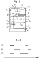
- an oven is shown in a highly simplified manner according to the second embodiment.
- An oven muffle 53 is located in a housing 51 and can be closed with an oven door 55, as a result of which the baking chamber 57 is formed is.
- an upper heat radiator 59, a lower heat radiator 61, a blower motor 63, a blower 65, a blower radiator 67 and a food support 69 are assigned to the baking chamber 57.
- embossments (not shown in more detail) between the bottom of the door 55 and the flange of the oven muffle 53, a steam outlet opening 70 is formed and thus an open system for steam cooking is always guaranteed.
- a control device 73 arranged in the upper region of the housing 51 can be actuated via operating elements 71. This is connected via control lines 75, in accordance with the first exemplary embodiment, to the components of the oven to be controlled. Furthermore, above the door 55 in the front area of the baking oven there is a water drawer 77 which can be pushed into and pulled out of the oven. At the bottom thereof there is an outlet opening through which the water can run into an evaporation device 79. A desired amount of steam of a predeterminable temperature is generated in the evaporation device 79 via heating elements (not shown) and fed into the baking chamber 57 from above via a steam feed pipe 81.
- the oven muffle 53 is connected to the atmosphere via a vapor channel 83 connected to its ceiling.
- a controllable bimetal flap 85 is arranged in the vapor channel 83, which closes the vapor channel 83 if necessary or releases the connection from the baking chamber 57 to the outside air.
- steam is introduced into the baking chamber 57 from above, which due to its buoyancy spreads from top to bottom, displaces the air in layers and down through the steam outlet opening 70 from the baking chamber 57.
- the steaming or modified cooking processes can be carried out in the same way as in the first exemplary embodiment. An undesired escape of the steam from the baking chamber 57 is avoided that the control device 73 closes the vapor channel 83 with the bimetallic valve 85.
- a hose-like steam distribution device 87 can be connected to the outlet opening of the steam supply pipe 81 in the area of the muffle ceiling, which presses the steam into the baking chamber only in the immediate vicinity of the food (broken lines).
Abstract
Description
Die vorliegende Erfindung betrifft einen Backofen nach dem Oberbegriff des Anspruches 1.The present invention relates to an oven according to the preamble of claim 1.
Ein derartiger Backofen ist bekannt aus der G 81 31 827.8, wobei bei der Zubereitung von Speisen in dem durch die Tür verschließbaren und mit einem steuerbaren Wrasenabzug versehenen Garraum ein Dampf-Luft-Gemisch als Wärmeträger umgewälzt wird. In einer Dämpfphase erzeugt die Verdampfungseinrichtung die benötigte Menge Dampf, die durch das Gebläserad in den Garraum gedrückt wird.Such an oven is known from
Nachteilig dabei ist, daß durch die Verwirbelung und die dadurch verursachte erhöhte Geschwindigkeit des Wärmeträgers Dampf der Wirkungsgrad des kondensativen Wärmeübergangs von dem Dampf auf das Gargut verschlechtert wird, daß durch die Vermischung von Luft und Dampf der Wirkungsgrad des Wärmeübergangs verschlechtert wird, und daß das Vorbeistreichen des Dampf-Luft-Gemisches infolge der Verwirbelung das unerwünschte Austrocknen der Oberflächenschicht des Gargutes fördert.The disadvantage here is that the turbulence and the resulting increased speed of the heat carrier steam deteriorate the efficiency of the condensation heat transfer from the steam to the food to be cooked, that the mixing of air and steam deteriorates the efficiency of the heat transfer, and that the sweeping of the steam-air mixture as a result of the turbulence, the undesirable drying out of the surface layer of the food promotes.
Aufgabe der vorliegenden Erfindung ist es deshalb, einen Backofen zum Dampfgaren und ein Garverfahren mit Dampf bereitzustellen, wobei mit geringem Energieaufwand günstige Backergebnisse erreichbar sind.The object of the present invention is therefore to provide an oven for steam cooking and a cooking method with steam, with favorable baking results being achievable with little energy expenditure.
Erfindungsgemäß ist dies dadurch erreicht, daß die Steuereinrichtung zumindest während des ersten Einleitens des Dampfes in den Backraum das Gebläse abgeschaltet hält. Der Dampf strömt aus der Verdampfungseinrichtung aufgrund seines Auftriebes von unten nach oben am Gargut vorbei oder breitet sich von oben nach unten, die Luft im Backraum verdrängend, entsprechend langsam aus. Es ist gewährleistet, daß im wesentlichen reiner Dampf mit einer nicht zu hohen Geschwindigkeit das Gargut umgibt und so der kondensative Wärmeübergang stattfindet.According to the invention this is achieved in that the control device keeps the fan switched off at least during the first introduction of the steam into the baking chamber. Due to its buoyancy, the steam flows out of the evaporation device from bottom to top past the food to be cooked or spreads from top to bottom, displacing the air in the baking chamber accordingly slowly. It is ensured that essentially pure steam surrounds the food to be cooked at a speed which is not too high, and thus the condensation heat transfer takes place.
Vorteilhafterweise heizt die Steuereinrichtung durch die Ansteuerung des Heizkörpers die Innenwandungen der Backofenmuffel und der Tür vor dem ersten Einleiten des Dampfes in den Backraum auf. Der Kondensationsvorgang konzentriert sich dadurch auf das Gargut. Ein unerwünschter Niederschlag des Dampfes an kalten Stellen der Backrauminnenwandung, insbesondere der Tür ist vermieden. Ein gleichmäßiges Aufheizen der Innenwandung ist gewährleistet, wenn die Steuereinrichtung das Gebläse während des Vorheizens zumindest zeitweise einschaltet.Advantageously, the control device heats up the inner walls of the oven muffle and the door before the first introduction of the steam into the baking chamber by activating the heating element. The condensation process is concentrated on the food. An undesirable precipitation of the steam at cold places on the inside of the baking chamber, especially the door, is avoided. A uniform heating of the inner wall is ensured if the control device switches on the fan at least temporarily during the preheating.
Gemäß einer bevorzugten Ausführungsform ist die Dampfaustrittsöffnung im unteren Bereich des Backraumes angeordnet. Da Dampf leichter als luft ist, füllt dieser den Backraum von oben nach unten, die zuvor im Backraum befindliche Luft nach unten verdrängend. Das heißt, daß beim Einleiten des Dampfes zunächst ausschließlich heiße Luft aus dem Backraum verdrängt wird und nicht der zur Wärmeübertragung vorgesehene Dampf. Das Befüllen des Backraumes mit Dampf kann zum einen durch eine dampfempfindliche Sensorik im Bereich der Dampfaustrittsöffnung gesteuert sein, die den ersten austretenden Dampf der Steuereinrichtung meldet, die daraufhin die Dampferzeugung und -einleitung in den Backraum beendet. Zum anderen kann die Dampfeinleitung auch über eine Zeitsteuerung beendet werden, wobei die zum Befüllen des Backraums mit Dampf erforderliche Zeit experimentell gewonnen wird. Die Dampfaustrittsöffnung kann sich hierbei sowohl an der Seiten als auch an der Rückwandung der Muffel befinden, es ist jedoch konstruktiv besonders einfach, ein offenes System dadurch zu realisieren, daß die Dampfaustrittsöffnung zwischen der Backofenmuffel bzw. deren Flansch und der Ofentür gebildet ist.According to a preferred embodiment, the steam outlet opening is arranged in the lower region of the baking chamber. Since steam is lighter than air, it fills the baking chamber from top to bottom, displacing the air previously in the baking chamber. This means that when the steam is introduced, only hot air is initially displaced from the baking chamber and not the steam intended for heat transfer. The filling of the baking chamber with steam can be controlled on the one hand by a steam-sensitive sensor system in the area of the steam outlet opening, which reports the first emerging steam to the control device, which then ends the steam generation and introduction into the baking chamber. On the other hand, the introduction of steam can also be stopped via a time control, the time required for filling the baking chamber with steam being obtained experimentally. The steam outlet opening can be both on the sides and on the rear wall of the muffle, but it is structurally particularly simple to implement an open system in that the steam outlet opening is formed between the oven muffle or its flange and the oven door.
Um eine Verschmutzung der Verdampfungseinrichtung oder der Dampfzuleitung zum Backraum durch Kondensat zu vermeiden, erfolgt die Einspeisung des Dampfes in den Backraum vorteilhafterweise in dessen oberen Bereich. Wenn die Verdampfungseinrichtung aus Platz- und Temperaturgründen jedoch unterhalb des Backraums anzuordnen ist und die Verbindungsleitungen von der eigentlichen Verdampfungseinrichtung zum Backraum kurz zu halten sind, ist es günstig, die Einspeisung des Dampfes in den Backraum in dessen unteren Bereich vorzunehmen.In order to avoid contamination of the evaporation device or the steam feed line to the baking chamber by condensate, the steam is advantageously fed into the baking chamber in the upper region thereof. However, if the evaporation device is to be arranged below the baking space for reasons of space and temperature and the connecting lines from the actual evaporation device to the baking space are to be kept short, it is advantageous to feed the steam into the baking space in the lower region thereof.
Nachfolgend sind anhand schematischer Darstellungen zwei Ausführungsbeispiele des erfindungsgemäßen Backofens und das erfindungsgemäße Garverfahren mit Dampf beschrieben. Es zeigt:
- Fig. 1
- in einer Schnittdarstellung einer Seitenansicht einen Backofen gemäß dem ersten Ausführungsbeispiel;
- Fig. 2
- in einer Schnittdarstellung einer Seitenansicht stark vereinfacht einen Backofen gemäß dem zweiten Ausführungsbeispiel und
- Fig. 3
- ein Ablaufdiagramm des Garverfahrens.
- Fig. 1
- in a sectional view of a side view of an oven according to the first embodiment;
- Fig. 2
- in a sectional view of a side view greatly simplified an oven according to the second embodiment and
- Fig. 3
- a flowchart of the cooking process.
Ein Backofen weist in einem Gehäuse 1 eine Backofenmuffel 3 auf, die allseitig von nicht gezeigtem Isoliermaterial umgeben ist. Die Muffel 3 ist an ihrer Vorderseite durch eine Backofentür 5 verschließbar, die mit einer Frontglasscheibe 6 versehen ist, und bildet den Back- bzw. Garraum 7. Durch Ziehen an einem an der Garraumtür 5 befestigten Griff wird der dahinter befindliche Garraum 7 der Bedienperson zugänglich. Im Bereich der Decke des Garraums 7 ist ein Oberhitze- bzw. Grillheizkörper 9 im Garraum angeordnet. Unterhalb des Bodens der Backofenmuffel 3 ist ein Unterhitze-Heizkörper 11 befestigt. Im Bereich der Rückwand der Backofenmuffel 3 ist außerhalb dieser ein Elektromotor 13 befestigt, der über eine durch die Rückwandung ragende Achse ein im Backraum 7 befindliches Gebläse 15 antreibt. Dieses ist von einem ringförmigen Gebläse-Heizkörper 17 umgeben (stark vereinfacht dargestellt). Zum Ablegen des Gargutes im Backraum 7 ist in diesem in verschiedenen Höhen ein Gargutträger 19 anbringbar, der selbst oder zwischen sich und den Seitenwandungen des Garraums 7 Öffnungen zum ungehinderten Strömen des Dampfes von unten nach oben bzw. umgekehrt und insbesondere nahe zum Gargut aufweist. Im unteren, vorderen Bereich des Garraums 7 befindet sich unterhalb eines Vorsprungs der Tür 5 eine Wrasenauslaß- bzw. Dampfaustrittsöffnung 20, die den Backraum 7 mit der Atmosphäre verbindet.An oven has in a housing 1 an oven muffle 3, which is surrounded on all sides by insulating material, not shown. The muffle 3 can be closed at the front by an
Unterhalb der Backofenmuffel 3 ist eine Verdampfungseinrichtung 21 entsprechend der deutschen Patentanmeldung P 44 27 460.2-16 der Anmelderin angeordnet. Der Unterhitze-Heizkörper 11 ist wärmetechnisch sowohl an den Muffelboden als auch an ein Dampfzuleitungsrohr 23 angekoppelt, das in den Garraum 7 mündet. Am entgegengesetzten Ende ist das Dampfzuleitungsrohr 23 Ober eine Dampfkupplung 25 an die eigentlichen Verdampfungseinrichtung 21 angekoppelt. Diese ist in dem unter dem Garraum 7 befindlichen Innenraum des Backofens in einem herausziehbaren Ofenschubkasten 27 untergebracht. Im Ofenschubkasten 27 ist ein Verdampfungsbehältnis 29 mit einem Deckel 30 und an der Unterseite des Bodens eine Dampfheizung 31 vorgesehen. Die Verdampfungseinrichtung 21 besteht weiterhin aus einem Wasserschubladen-Führungsrohr 33 mit einer Wasserablauföffnung, einem Schwimmer 35 im Schwimmerführungsrohr und einer Wasserschublade 37 gemäß der P 44 27 460.2-16. Die Funktion der Verdampfungseinrichtung 21 ist ebenfalls in dieser Anmeldung beschrieben.An
Im oberen Bereich der Frontseite des Backofens sind verschiedene Anzeige- und Bedienungselemente 41 angeordnet. Dahinter innerhalb des Gehäuses 1 ist eine Steuereinrichtung 43 plaziert, die über Steuerleitungen 45 zumindest mit den Heizkörpern 9, 11, 17, 31 und dem Gebläse 13, 15 verbunden ist. Im Betrieb stellt eine Bedienperson an den Bedienelementen 41 den gewünschten Backvorgang ein, der über die Steuereinrichtung gesteuert wird. Beim Dampfgaren werden zunächst die Innenwandungen der Muffel 3 und der Tür 5 auf etwa 100 bis 120°C vorgeheizt. Dabei steuert die Steuereinrichtung 43 das Gebläse 17 an, um eine gleichmäßige Erwärmung der Garraumwandung zu gewährleisten. Danach wird das Gebläse 15 bzw. der Motor 13 durch die Steuereinrichtung 43 abgeschaltet und die Dampferzeugung bzw. die Einleitung des Dampfes in den Garraum 7 gestartet. Dazu aktiviert die Steuereinrichtung 43 den Dampfheizkörper 31. Über das Dampfzuleitungsrohr 23 strömt der im Verdampfungsbehältnis 29 erzeugte Dampf in den Garraum 7 und von dort steigt der Dampf aufgrund seines im Vergleich zu Luft geringeren spezifischen Gewichts langsam nach oben. Dabei strömt er am Gargutträger 19 vorbei bzw. durch ihn durch am Gargut vorbei nach oben. Der Garraum 7 füllt sich dann von oben nach unten schichtenweise, die heiße Luft nach unten verdrängend. Die heiße Luft entweicht durch die Dampfaustrittsöffnung 20 ins Freie. Nach einer vorbestimmten Zeit beendet die Steuereinrichtung 43 die Dampferzeugung, nämlich wenn der Garraum 7 im wesentlichen mit Dampf gefüllt ist bzw. gewährleistet ist, daß das Gargut vollständig von einer homogenen Dampfatmosphäre umgeben ist. Um das Bedampfen des Gargutes günstig zu gestalten, wird in den Garraum 7 zyklisch Dampf eingespeist. Bei der Durchführung besonderer Garvorgänge kann die Steuereinrichtung 43 auch ausgewählte Heizkörper zur Wärmebeaufschlagung des Gargutes in Kombination mit oder gänzlich ohne Dampf ansteuern.Various display and operating elements 41 are arranged in the upper area of the front of the oven. A
In Figur 2 ist gemäß dem zweiten Ausführungsbeispiel ein Backofen stark vereinfacht gezeigt. In einem Gehäuse 51 befindet sich eine Backofenmuffel 53, die mit einer Backofentür 55 verschließbar ist, wodurch der Backraum 57 gebildet ist. Entsprechend dem ersten Ausführungsbeispiel sind dem Backraum 57 ein Oberhitzeheizkörper 59, ein Unterhitzeheizkörper 61, ein Gebläsemotor 63, ein Gebläse 65, ein Gebläseheizkörper 67 und ein Gargutträger 69 zugeordnet. Mittels nicht näher gezeigter Prägungen zwischen dem Boden der Tür 55 und dem Flansch der Backofenmuffel 53 ist eine Dampfaustrittsöffnung 70 gebildet und damit stets ein offenes System beim Dampfgaren gewährleistet. Über Bedienelemente 71 ist eine im oberen Bereich des Gehäuses 51 angeordnete Steuereinrichtung 73 betätigbar. Diese ist über Steuerleitungen 75, entsprechend dem ersten Ausführungsbeispiel, mit den zu steuernden Komponenten des Backofens verbunden. Weiterhin befindet sich oberhalb der Tür 55 im Frontbereich des Backofens eine in den Backofen einschiebbar und herausziehbar gelagerte Wasserschublade 77. An deren Boden weist diese ein Auslauföffnung auf, durch die das Wasser in eine Verdampfungseinrichtung 79 laufen kann. Über nicht gezeigte Heizelemente wird in der Verdampfungseinrichtung 79 eine gewünschte Menge Dampf einer vorgebbaren Temperatur erzeugt und über ein Dampfzuleitungsrohr 81 von oben in den Backraum 57 eingespeist. Die Backofenmuffel 53 ist über einen an deren Decke angeschlossenen Wrasenkanal 83 mit der Atmosphäre verbunden. Dabei ist in dem Wrasenkanal 83 eine steuerbare Bimetallklappe 85 angeordnet, die bei Bedarf den Wrasenkanal 83 verschließt oder die Verbindung vom Backraum 57 zur Außenluft freigibt. Beim Betrieb des Backofens wird von oben in den Backraum 57 Dampf eingeleitet, der aufgrund seines Auftriebes sich von oben nach unten ausbreitend, schichtenweise die Luft nach unten und durch die Dampfaustrittsöffnung 70 aus dem Backraum 57 verdrängt. Die Bedampfung bzw. abgewandelte Garprozesse können entsprechend wie im ersten Ausführungsbeispiel durchgeführt werden. Ein unerwünschtes Entweichen des Dampfes aus dem Backraum 57 ist dadurch vermieden, daß die Steuereinrichtung 73 mit der Bimetallklappe 85 den Wrasenkanal 83 verschließt. Um den Dampf direkt an das Gargut leiten zu können, kann an die Austrittsöffnung des Dampfzuleitungsrohres 81 im Bereich der Muffeldecke eine beispielsweise schlauchförmige Dampfverteilungseinrichtung 87 angeschlossen sein, die den Dampf erst in unmittelbarer Nähe des Gargutes in den Backraum drückt (unterbrochene Linien).In Figure 2, an oven is shown in a highly simplified manner according to the second embodiment. An
In dem in Figur 3 dargestellten Garprozeß ist das Eintreten eines Ereignisses über der Zeitachse (t) durch eine waagerechte Linie gezeigt. Dabei bedeuten GE: Gebläse eingeschaltet, DE: Dampf eingeleitet und HE: Heizung eingeschaltet.In the cooking process shown in Figure 3, the occurrence of an event on the time axis (t) is shown by a horizontal line. GE means: fan switched on, DE: steam introduced and HE: heating switched on.
Claims (8)
Applications Claiming Priority (2)
| Application Number | Priority Date | Filing Date | Title |
|---|---|---|---|
| DE19537751A DE19537751A1 (en) | 1995-10-10 | 1995-10-10 | Oven for steaming |
| DE19537751 | 1995-10-10 |
Publications (2)
| Publication Number | Publication Date |
|---|---|
| EP0768055A1 true EP0768055A1 (en) | 1997-04-16 |
| EP0768055B1 EP0768055B1 (en) | 2002-03-27 |
Family
ID=7774511
Family Applications (1)
| Application Number | Title | Priority Date | Filing Date |
|---|---|---|---|
| EP96113327A Expired - Lifetime EP0768055B1 (en) | 1995-10-10 | 1996-08-20 | Baking oven for steam cooking |
Country Status (2)
| Country | Link |
|---|---|
| EP (1) | EP0768055B1 (en) |
| DE (2) | DE19537751A1 (en) |
Cited By (7)
| Publication number | Priority date | Publication date | Assignee | Title |
|---|---|---|---|---|
| EP1036990A3 (en) * | 1999-02-19 | 2000-09-27 | BSH Bosch und Siemens Hausgeräte GmbH | Steam cooking device, in particular baking oven for steam cooking |
| CH691280A5 (en) * | 2000-06-20 | 2001-06-29 | V Zug Ag | Steam cooking device for heating food has cooking space supplied with steam from boiler and pre-heated via electric heating device |
| US7309846B2 (en) | 2003-03-27 | 2007-12-18 | Bsh Bosch Und Siemens Hausgeraete Gmbh | Method for operating a baking oven |
| US7745763B2 (en) | 2005-07-11 | 2010-06-29 | Whirlpool Corporation | Method for baking bread using steam |
| US7867534B2 (en) | 2006-10-18 | 2011-01-11 | Whirlpool Corporation | Cooking appliance with steam generator |
| CN104287612A (en) * | 2014-10-30 | 2015-01-21 | 广东美的厨房电器制造有限公司 | Steam oven |
| US10123556B2 (en) | 2005-05-06 | 2018-11-13 | Whirlpool Corporation | Method for cooking food using steam |
Families Citing this family (6)
| Publication number | Priority date | Publication date | Assignee | Title |
|---|---|---|---|---|
| DE19812465C5 (en) * | 1998-03-23 | 2011-06-01 | Miwe Michael Wenz Gmbh | Oven with steam generator |
| DE19858134A1 (en) | 1998-12-16 | 2000-06-21 | Bsh Bosch Siemens Hausgeraete | Cooking device and method for the heat treatment of a food to be steamed |
| DE19957721A1 (en) * | 1999-11-30 | 2001-05-31 | Bsh Bosch Siemens Hausgeraete | Baking oven has hot air blower with ventilator offset downwards non-symmetrical to oven height |
| DE10161184A1 (en) * | 2001-12-13 | 2003-07-10 | Aeg Hausgeraete Gmbh | Process for operating a cooking oven and cooking oven |
| DE10260965A1 (en) * | 2002-12-20 | 2004-09-09 | Maschinenfabrik Kurt Neubauer Gmbh & Co | Steam cooking process for food, has moisture laden air circulated within to oven at a low temperature to moisturize the food before steam generation |
| US8207477B2 (en) | 2007-11-26 | 2012-06-26 | Whirlpool Corporation | Method for cooking vegetables using steam |
Citations (5)
| Publication number | Priority date | Publication date | Assignee | Title |
|---|---|---|---|---|
| DE8131827U1 (en) * | 1981-10-31 | 1983-04-14 | Meister, Siegfried, 8910 Landsberg | DEVICE FOR HEAT-TREATING FOODSTUFFS BY MEANS OF A VAPOR-AIR MIXTURE |
| EP0277337A2 (en) * | 1987-02-05 | 1988-08-10 | Electrolux-Juno Küchentechnik GmbH | Cooking appliance with electric heating of a cooking room and method of runing such a cooking appliance |
| US4851644A (en) * | 1987-05-14 | 1989-07-25 | Delaware Capital Formation, Inc. | Electric combination oven |
| DE4225696A1 (en) * | 1992-08-04 | 1994-02-10 | Wiesheu Gmbh | Device for the heat treatment of food |
| DE4403386C1 (en) * | 1994-02-04 | 1995-06-01 | Wiesheu Wiwa Gmbh | Food heat treatment assembly temperature sensor |
-
1995
- 1995-10-10 DE DE19537751A patent/DE19537751A1/en not_active Withdrawn
-
1996
- 1996-08-20 DE DE59608950T patent/DE59608950D1/en not_active Expired - Lifetime
- 1996-08-20 EP EP96113327A patent/EP0768055B1/en not_active Expired - Lifetime
Patent Citations (5)
| Publication number | Priority date | Publication date | Assignee | Title |
|---|---|---|---|---|
| DE8131827U1 (en) * | 1981-10-31 | 1983-04-14 | Meister, Siegfried, 8910 Landsberg | DEVICE FOR HEAT-TREATING FOODSTUFFS BY MEANS OF A VAPOR-AIR MIXTURE |
| EP0277337A2 (en) * | 1987-02-05 | 1988-08-10 | Electrolux-Juno Küchentechnik GmbH | Cooking appliance with electric heating of a cooking room and method of runing such a cooking appliance |
| US4851644A (en) * | 1987-05-14 | 1989-07-25 | Delaware Capital Formation, Inc. | Electric combination oven |
| DE4225696A1 (en) * | 1992-08-04 | 1994-02-10 | Wiesheu Gmbh | Device for the heat treatment of food |
| DE4403386C1 (en) * | 1994-02-04 | 1995-06-01 | Wiesheu Wiwa Gmbh | Food heat treatment assembly temperature sensor |
Cited By (10)
| Publication number | Priority date | Publication date | Assignee | Title |
|---|---|---|---|---|
| EP1036990A3 (en) * | 1999-02-19 | 2000-09-27 | BSH Bosch und Siemens Hausgeräte GmbH | Steam cooking device, in particular baking oven for steam cooking |
| CH691280A5 (en) * | 2000-06-20 | 2001-06-29 | V Zug Ag | Steam cooking device for heating food has cooking space supplied with steam from boiler and pre-heated via electric heating device |
| EP1166694A1 (en) | 2000-06-20 | 2002-01-02 | V-Zug AG | Steam cooking vessel with preheating |
| US7309846B2 (en) | 2003-03-27 | 2007-12-18 | Bsh Bosch Und Siemens Hausgeraete Gmbh | Method for operating a baking oven |
| US10123556B2 (en) | 2005-05-06 | 2018-11-13 | Whirlpool Corporation | Method for cooking food using steam |
| US7745763B2 (en) | 2005-07-11 | 2010-06-29 | Whirlpool Corporation | Method for baking bread using steam |
| US7867534B2 (en) | 2006-10-18 | 2011-01-11 | Whirlpool Corporation | Cooking appliance with steam generator |
| US8704138B2 (en) | 2006-10-18 | 2014-04-22 | Whirlpool Corporation | Cooking appliance with steam generator |
| CN104287612A (en) * | 2014-10-30 | 2015-01-21 | 广东美的厨房电器制造有限公司 | Steam oven |
| CN104287612B (en) * | 2014-10-30 | 2016-05-18 | 广东美的厨房电器制造有限公司 | Steam roaster |
Also Published As
| Publication number | Publication date |
|---|---|
| DE19537751A1 (en) | 1997-04-17 |
| DE59608950D1 (en) | 2002-05-02 |
| EP0768055B1 (en) | 2002-03-27 |
Similar Documents
| Publication | Publication Date | Title |
|---|---|---|
| EP0383366B1 (en) | Method for steam-cooking food | |
| EP2697569B1 (en) | Steam cooking appliance, in particular a steam oven | |
| EP0768055B1 (en) | Baking oven for steam cooking | |
| DE3443477A1 (en) | METHOD AND DEVICE FOR OPERATING AN OPERATION WITH A CIRCULATED HOT AIR OR WATER STEAM | |
| EP3190937B1 (en) | Cooking attachment for a heatable vessel of a food processor | |
| EP0319673A1 (en) | Device and method for controlling the steam in a steam-proofing apparatus | |
| DE2851671C2 (en) | Steam cooker | |
| WO1999004202A2 (en) | Apparatus for cooking dishes by heating | |
| DE3821205C2 (en) | Combined steam and hot air recirculation device | |
| DE2541374A1 (en) | Food simmering oven - with satd. steam circulated along walls towards food by circulating fan and guide plates | |
| EP0695503B1 (en) | Oven for steam-cooking | |
| DE2166255A1 (en) | INCINERATION CLOSET | |
| WO2021170402A1 (en) | Domestic steam cooking appliance and method for operating a domestic steam cooking appliance | |
| DE4333585C2 (en) | Stove with an oven that can be used as an oven, which can be heated electrically or by gas | |
| DE19858134A1 (en) | Cooking device and method for the heat treatment of a food to be steamed | |
| DE2405515B2 (en) | Method and device for melting solid food to be cooked | |
| DE102009001739B3 (en) | Steam cooking device, has control unit heated to specific temperature and heating unit, which generates hot air, is reduced in power or switched off during steam generation, where steam generation takes place in operating mode of device | |
| DE2659865A1 (en) | Heat treatment device for foodstuffs - uses steam and air mixt. with controlled heating elements forced over foodstuffs by centrifugal blower | |
| DE102020212058A1 (en) | Household steamer with superheater | |
| DE3639872C2 (en) | Cooking appliance | |
| DE2857126A1 (en) | Hot air circulation baking oven - with three passes of flue gases through heat exchanger | |
| DE102020216520A1 (en) | Household steamer with superheater module | |
| EP1176895B1 (en) | Method and device for cooking eggs | |
| EP3118528B1 (en) | Cooking system for cooking and flavouring products to be cooked | |
| WO2013107603A1 (en) | Cooking device and method for operating a cooking device |
Legal Events
| Date | Code | Title | Description |
|---|---|---|---|
| PUAI | Public reference made under article 153(3) epc to a published international application that has entered the european phase |
Free format text: ORIGINAL CODE: 0009012 |
|
| AK | Designated contracting states |
Kind code of ref document: A1 Designated state(s): CH DE FR IT LI SE |
|
| 17P | Request for examination filed |
Effective date: 19970926 |
|
| RAP1 | Party data changed (applicant data changed or rights of an application transferred) |
Owner name: BSH BOSCH UND SIEMENS HAUSGERAETE GMBH |
|
| GRAG | Despatch of communication of intention to grant |
Free format text: ORIGINAL CODE: EPIDOS AGRA |
|
| 17Q | First examination report despatched |
Effective date: 20010309 |
|
| GRAG | Despatch of communication of intention to grant |
Free format text: ORIGINAL CODE: EPIDOS AGRA |
|
| GRAG | Despatch of communication of intention to grant |
Free format text: ORIGINAL CODE: EPIDOS AGRA |
|
| GRAH | Despatch of communication of intention to grant a patent |
Free format text: ORIGINAL CODE: EPIDOS IGRA |
|
| GRAH | Despatch of communication of intention to grant a patent |
Free format text: ORIGINAL CODE: EPIDOS IGRA |
|
| GRAH | Despatch of communication of intention to grant a patent |
Free format text: ORIGINAL CODE: EPIDOS IGRA |
|
| GRAA | (expected) grant |
Free format text: ORIGINAL CODE: 0009210 |
|
| AK | Designated contracting states |
Kind code of ref document: B1 Designated state(s): CH DE FR IT LI SE |
|
| REG | Reference to a national code |
Ref country code: CH Ref legal event code: NV Representative=s name: SIEMENS SCHWEIZ AG Ref country code: CH Ref legal event code: EP |
|
| REF | Corresponds to: |
Ref document number: 59608950 Country of ref document: DE Date of ref document: 20020502 |
|
| ET | Fr: translation filed | ||
| PLBE | No opposition filed within time limit |
Free format text: ORIGINAL CODE: 0009261 |
|
| STAA | Information on the status of an ep patent application or granted ep patent |
Free format text: STATUS: NO OPPOSITION FILED WITHIN TIME LIMIT |
|
| 26N | No opposition filed |
Effective date: 20021230 |
|
| REG | Reference to a national code |
Ref country code: CH Ref legal event code: PCAR Free format text: SIEMENS SCHWEIZ AG;INTELLECTUAL PROPERTY FREILAGERSTRASSE 40;8047 ZUERICH (CH) |
|
| PGFP | Annual fee paid to national office [announced via postgrant information from national office to epo] |
Ref country code: FR Payment date: 20090819 Year of fee payment: 14 |
|
| PGFP | Annual fee paid to national office [announced via postgrant information from national office to epo] |
Ref country code: SE Payment date: 20090821 Year of fee payment: 14 Ref country code: CH Payment date: 20090824 Year of fee payment: 14 |
|
| PGFP | Annual fee paid to national office [announced via postgrant information from national office to epo] |
Ref country code: IT Payment date: 20090825 Year of fee payment: 14 |
|
| EUG | Se: european patent has lapsed | ||
| REG | Reference to a national code |
Ref country code: CH Ref legal event code: PL |
|
| PG25 | Lapsed in a contracting state [announced via postgrant information from national office to epo] |
Ref country code: LI Free format text: LAPSE BECAUSE OF NON-PAYMENT OF DUE FEES Effective date: 20100831 Ref country code: CH Free format text: LAPSE BECAUSE OF NON-PAYMENT OF DUE FEES Effective date: 20100831 |
|
| REG | Reference to a national code |
Ref country code: FR Ref legal event code: ST Effective date: 20110502 |
|
| PG25 | Lapsed in a contracting state [announced via postgrant information from national office to epo] |
Ref country code: IT Free format text: LAPSE BECAUSE OF NON-PAYMENT OF DUE FEES Effective date: 20100820 |
|
| PG25 | Lapsed in a contracting state [announced via postgrant information from national office to epo] |
Ref country code: FR Free format text: LAPSE BECAUSE OF NON-PAYMENT OF DUE FEES Effective date: 20100831 |
|
| PGFP | Annual fee paid to national office [announced via postgrant information from national office to epo] |
Ref country code: DE Payment date: 20110831 Year of fee payment: 16 |
|
| PG25 | Lapsed in a contracting state [announced via postgrant information from national office to epo] |
Ref country code: SE Free format text: LAPSE BECAUSE OF NON-PAYMENT OF DUE FEES Effective date: 20100821 |
|
| PG25 | Lapsed in a contracting state [announced via postgrant information from national office to epo] |
Ref country code: DE Free format text: LAPSE BECAUSE OF NON-PAYMENT OF DUE FEES Effective date: 20130301 |
|
| REG | Reference to a national code |
Ref country code: DE Ref legal event code: R119 Ref document number: 59608950 Country of ref document: DE Effective date: 20130301 |