EP0767454A1 - Manually scannable code read apparatus - Google Patents
Manually scannable code read apparatus Download PDFInfo
- Publication number
- EP0767454A1 EP0767454A1 EP96115822A EP96115822A EP0767454A1 EP 0767454 A1 EP0767454 A1 EP 0767454A1 EP 96115822 A EP96115822 A EP 96115822A EP 96115822 A EP96115822 A EP 96115822A EP 0767454 A1 EP0767454 A1 EP 0767454A1
- Authority
- EP
- European Patent Office
- Prior art keywords
- code
- read
- imaging
- scan
- multimedia information
- Prior art date
- Legal status (The legal status is an assumption and is not a legal conclusion. Google has not performed a legal analysis and makes no representation as to the accuracy of the status listed.)
- Granted
Links
Images


Classifications
-
- G—PHYSICS
- G11—INFORMATION STORAGE
- G11C—STATIC STORES
- G11C13/00—Digital stores characterised by the use of storage elements not covered by groups G11C11/00, G11C23/00, or G11C25/00
- G11C13/04—Digital stores characterised by the use of storage elements not covered by groups G11C11/00, G11C23/00, or G11C25/00 using optical elements ; using other beam accessed elements, e.g. electron or ion beam
-
- G—PHYSICS
- G06—COMPUTING; CALCULATING OR COUNTING
- G06K—GRAPHICAL DATA READING; PRESENTATION OF DATA; RECORD CARRIERS; HANDLING RECORD CARRIERS
- G06K1/00—Methods or arrangements for marking the record carrier in digital fashion
- G06K1/12—Methods or arrangements for marking the record carrier in digital fashion otherwise than by punching
-
- G—PHYSICS
- G06—COMPUTING; CALCULATING OR COUNTING
- G06K—GRAPHICAL DATA READING; PRESENTATION OF DATA; RECORD CARRIERS; HANDLING RECORD CARRIERS
- G06K7/00—Methods or arrangements for sensing record carriers, e.g. for reading patterns
- G06K7/10—Methods or arrangements for sensing record carriers, e.g. for reading patterns by electromagnetic radiation, e.g. optical sensing; by corpuscular radiation
-
- G—PHYSICS
- G11—INFORMATION STORAGE
- G11B—INFORMATION STORAGE BASED ON RELATIVE MOVEMENT BETWEEN RECORD CARRIER AND TRANSDUCER
- G11B20/00—Signal processing not specific to the method of recording or reproducing; Circuits therefor
- G11B20/10—Digital recording or reproducing
-
- G—PHYSICS
- G11—INFORMATION STORAGE
- G11B—INFORMATION STORAGE BASED ON RELATIVE MOVEMENT BETWEEN RECORD CARRIER AND TRANSDUCER
- G11B7/00—Recording or reproducing by optical means, e.g. recording using a thermal beam of optical radiation by modifying optical properties or the physical structure, reproducing using an optical beam at lower power by sensing optical properties; Record carriers therefor
- G11B7/002—Recording, reproducing or erasing systems characterised by the shape or form of the carrier
- G11B7/0033—Recording, reproducing or erasing systems characterised by the shape or form of the carrier with cards or other card-like flat carriers, e.g. flat sheets of optical film
-
- G—PHYSICS
- G11—INFORMATION STORAGE
- G11B—INFORMATION STORAGE BASED ON RELATIVE MOVEMENT BETWEEN RECORD CARRIER AND TRANSDUCER
- G11B7/00—Recording or reproducing by optical means, e.g. recording using a thermal beam of optical radiation by modifying optical properties or the physical structure, reproducing using an optical beam at lower power by sensing optical properties; Record carriers therefor
- G11B7/007—Arrangement of the information on the record carrier, e.g. form of tracks, actual track shape, e.g. wobbled, or cross-section, e.g. v-shaped; Sequential information structures, e.g. sectoring or header formats within a track
Definitions
- the present invention relates generally to a code read apparatus for reading codes recorded on a recording medium such as paper, and more particularly to a manually scannable code read apparatus for optically reading, by manual scan, code patterns recorded on a recording medium such as paper.
- code patterns are optically readable and represent so-called multimedia information including audio information such as sound and music, video information obtained from a camera, a video apparatus, etc., and digital code data obtained from a personal computer, a word processor, etc.
- the read code patterns are reproduced as original multimedia information.
- optical cards and optical (magnetooptical) disks are known as conventional optical recording media.
- a mechanical scan system i.e. an automatic scan system
- the optical card is reciprocally moved at a predetermined speed, thereby causing the detection element to scan relative to the optical card.
- the optical (magnetooptical) disk is rotated at a predetermined speed, thereby causing the detection element to scan.
- these conventional detection elements for optical recording media detect an area with a size less than the width of a recording track and less than the interval of recording pits. Specifically, a "point” sensor is moved relative to an optical recording medium to trace the recording track. Thus, “length” information is reproduced as "time” information.
- an error in speed of the optical recording medium is equal to an error in length (interval) of recorded information units, an allowable variation in speed is several-ten percent or less, although it depends on variation frequency.
- means for canceling the speed variation is provided by adopting a self-clock system in which sync clocks are produced from reproduced data. In fact, however, the degree of allowance is as mentioned above.
- the optical recording medium must be driven by a servo-controlled driving mechanism, and cannot be driven manually. This results in an increase in cost and size of the apparatus.
- a bar-code reader for reading bar codes recorded on a recording medium such as paper is known as manual scan apparatus.
- the bar-code reader too, cannot read bar codes unless the scan speed is within a predetermined range.
- the probability of reading of the manual scan type bar-code reader is not good.
- the manual scan type bar-code reader has not widely been accepted in the market.
- the present invention has been made in consideration of the above circumstances, and the object thereof is to provide a code read apparatus capable of manual scanning, with an increased degree of freedom with respect to scan speed.
- a manually scannable code read apparatus for reading, by manual scan, an optically readable code recorded on a recording medium, said code representing multimedia information including at least one of sound information, image information and text data, said apparatus comprising:
- a manually scannable code read apparatus for reading, by manual scan, an optically readable code recorded on a recording medium, said code representing multimedia information including at least one of sound information, image information and text data, said apparatus comprising:
- the dot code is recorded on an information recording medium such as paper in the form of a two-dimensional code pattern comprising two-dimensionally arranged dots as image information or coded information which can be transmitted by facsimile and copied in large number at low cost.
- the coded information represents multimedia information including at least one of audio information, video information and digital code data.
- the dot code 10 comprises blocks 10A arranged in a matrix.
- Each block 10A has data dots of a predetermined unit.
- Each block 10A includes a data area 10C containing data dots 10B arranged in accordance with the content of information, and block address dots 10D indicative of the address of the associated block, which are arranged in a predetermined relationship with the data area 10C.
- each block 10A has markers 10E at predetermined positions, e.g. at four corners, and matching pattern dots 10F arranged in a predetermined relationship with the markers 10E, e.g. between the markers adjacent to each other in a first direction.
- the address dots 10D are arranged in a predetermined relationship with the markers 10E, e.g.
- Each of the pattern dots 10F, address dots 10D and data dots 10B arranged within the data area 10C has the same size.
- Each marker 10E is formed as a dot greater in size than the other dots 10F, 10D and 10B.
- the marker 10E is recorded on the recording medium as a circular dot having a diameter equal to 7 data dots.
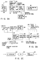
- FIG. 2A shows the structure of this code read apparatus
- FIG. 2B shows the structure of a dot detection section shown in FIG. 2A
- FIG. 2C shows the structure of an error correction (ECC)/restoration section shown in FIG. 2A.
- ECC error correction
- a light source (not shown) provided in an imaging section 20 illuminates the dot code 10 recorded on the recording medium, and reflection light is guided through a focusing optical system (not shown) of lenses, etc. and detected as an image signal by an area sensor 20A such as a charge-coupled device (CDD) for converting optical information to an electric signal.
- the image signal is amplified by a pre-amplifier (not shown) and output to a dot detection section 30.
- the area sensor 20A outputs the image signal in accordance with a first clock signal CLK1 generated by a clock generator 40.
- the imaging cycle can be changed by varying the frequency of the first clock signal CLK1.
- the dot detection section 30 comprises two memories, i.e. a dot image storage section 30A and a block storage section 30B, a sample/hold (S/H) circuit 30C, an analog/digital (A/D) converter 30D, a binarizing circuit 30E, a marker detection section 30F, a read point calculator 30G, a read section 30H, a demodulator 30I, and a controller 30J.
- a dot image storage section 30A and a block storage section 30B i.e. a dot image storage section 30A and a block storage section 30B, a sample/hold (S/H) circuit 30C, an analog/digital (A/D) converter 30D, a binarizing circuit 30E, a marker detection section 30F, a read point calculator 30G, a read section 30H, a demodulator 30I, and a controller 30J.
- the image signal output from the imaging section 20 is sampled/held by the S/H circuit 30C and converted to a digital signal by the A/D converter 30D.
- the digital signal is binarized by the binarizing circuit 30E and then stored in the dot image storage section 30A.
- the image data stored in the dot image storage section 30A is once read out and fed to the marker detection section 30F.
- the marker detection section 30F detects the marker 10E of each block.
- the extraction and detection of the marker is performed by, e.g. erosion process, as disclosed in EP 0,717,398 A3 (corresponding to U.S. Patent Application Serial No. 08/571,776 filed in the U.S. on December 13, 1995) by the same applicant as the present application.
- the read point calculator 30G detects the pattern dots 10F and detects, by using the pattern dots 10F, the true center of the marker 10E as data read reference point.
- the address of the block 10A is detected on the basis of the address dots 10D between the true centers of the markers 10E.
- the distance between the true centers of the markers is divided at predetermined intervals.
- the read points of the data dots 10B within the data area 10C of each block are calculated.
- the read section 30H reads out image data from the dot image storage section 30A.
- the read-out image data indicates the pattern of the data dots 10B. Since the dot code 10 was subjected to modulation, e.g. 8-10 modulation, at the time of recording, the dot code 10 is subjected to 10-8 demodulation in the demodulator 30I.
- the demodulated data is stored in the block storage section 30B.
- the controller 30J in accordance with a second clock signal CLK2 (having a predetermined relationship with the first clock signal CLK1) generated from the clock generator 40, the controller 30J produces control signals so that the operations of the S/H circuit 30C, A/D converter 30D, binarizing circuit 30E, marker detection section 30F, read point calculator 30G, read section 30H and demodulator 30I may match with the imaging cycle of the area sensor 20A.
- the imaging cycle is varied by a frequency indication signal input from a frequency indication section 50.
- the controller 30J produces a frequency control signal to control the clock generator 40 so that the frequency of the first clock signal CLK1 generated by the clock generator 40 may correspond to the frequency indicated by the frequency indication signal.
- the data stored in the block storage section 30B is processed by the ECC/restoration section 60. Specifically, the data read out from the block storage section 30B is first subjected to a de-interleave process in a de-interleave section 60A and then subjected to error correction in an ECC section 60B. In a data expansion section 60C, the data is subjected to an expansion process corresponding to the compression process carried out at the time of recording. The resultant data is output to an output section (not shown). Specifically, if the data is multi-value image information of, e.g. natural image, it is subjected to an expansion process corresponding to, e.g. JPEG. If the data is binary image information of, e.g.
- the handwritten letter or graph it is subjected to an expansion process corresponding to, e.g. MR/MH/MMR.
- the data is a character or a line
- it is first subjected to Huffman coding, Lempe-Ziv coding, etc. and then converted to display data.
- the display data is converted to an analog signal and displayed on a display such as a CRT (TV monitor).
- the data is sound information, it is subjected to an expansion process corresponding to, e.g. ADPCM.
- the expanded data is converted to an analog signal and the analog signal is supplied to a speaker, a headphone, or other sound output equipment.
- the character data or line data may be directly output to a page printer, a plotter, etc.
- the character data may be printed on paper as word-processed character, and the line data may be plotted as line image or figure.
- At least the imaging section 20 is constituted as scan section housed in a pen-like housing which is designed for manual scanning operation.
- the manual scan operation is performed in a manner similar to the manner in which a line is drawn freehand by means of a pencil, etc.
- an adult person with no special skill draws a line freehand at a speed of about one hundred and several-ten mm/s.
- the length of a line which can be drawn smoothly in one stroke is normally about 20 cm. This length corresponds to the width of "A4" sheet placed vertical. In the case of child, the speed of drawing is lower and about several-ten mm/s.
- the allowable scan speed range is determined based on the above values in consideration of easy operations for the user.
- FIG. 3A shows experimental data on the speed for scanning the dot code 10 by means of the pen-type scanner.
- the data values may vary depending on the friction between the read surface and the scanner.
- general conditions were set for the dot code 10. Specifically, the dot code 10 was recorded by ink on a paper sheet with smooth surface. The size of one dot is several-ten ⁇ m. The area of contact between the scanner and paper sheet is up to 2 cm 2 .
- FIGS. 3B and 3C show more detailed data for adults.
- a variance in maximum scan speeds in respective scan operations is plotted.
- the average of maximum values is about 111 mm/s. Even if the variance is considered, the maximum value is about 165 mm/s.
- FIG. 4 schematically shows the variation in speed in a single scan operation.
- the variation in speed is expressed by a trapezoidal speed pattern comprising an acceleration component at the beginning of scan, a substantially constant speed component, and a deceleration speed component after the end of scan.
- the maximum scan speed is observed in the substantially constant speed component.
- the code read apparatus is designed based on such specifications that the maximum speed is 160 to 200 mm/s and the scan speed ranges between the maximum value and substantially zero.
- the manual scan operation of the apparatus can be performed by the users from adults to children.
- FIG. 5A shows the state of actual scanning.
- An imaging screen 70 of the area sensor 20A comprises m ⁇ n blocks 10A.
- the imaging screen 70 comprises 4 ⁇ 3 blocks.
- numbers in the respective blocks indicate block addresses.
- a dot code 10 has a format in which at least one row of blocks within effective blocks 80 overlap.
- the blocks of the uppermost row and the blocks of the lowermost row are overlap blocks 82. Even if the position of the scanner is displaced vertically during manual scan due to motion of the hand, all blocks 10A can be imaged if the degree of displacement is within one block.
- the distance of overlap (in the scan direction) between a certain imaging screen and the next imaging screen is equal to greater than one block, irrespective of the number of blocks in the imaging screen, as shown in FIG. 5B, it will not occur that the block 10A is covered only in the defective state.
- FIG. 6A shows the state in which coverage has reached a front portion of the right-end block 84 in a certain imaging screen.
- the right-end block 84 cannot be imaged.
- the previous block is covered and thus the previously incompletely covered right-end block 84 is completely covered this time. Accordingly, the right-end block 84 can be imaged in the next imaging screen.
- FIG. 6B shows the state in which coverage has reached to a middle portion of the right-end block 84 in a certain imaging screen.
- the right-end block 84 cannot be imaged.
- the middle portion of the previous block is covered and thus the previously incompletely covered right-end block 84 is completely covered this time.
- FIG. 6C shows the state in which the right-end block 84 in a certain imaging screen has been covered, except for a small right-end portion thereof.
- the right-end block 84 cannot be imaged because of the presence of the non-covered right-end portion.
- the previous block is covered and thus the previously incompletely covered right-end block 84 is completely covered this time.
- all blocks 10A can be imaged if there is an overlap of at least one block in the imaging screen 70 in the scan direction.
- the code read apparatus of this embodiment is constructed such that there is an overlap of at least one block in the imaging screen 70 in the scan direction.
- this apparatus is designed in the following manner.
- FIG. 8 shows data obtained when the values shown in FIG. 7 and various values of imaging cycle t, i.e. imaging time interval, were substituted in equation (1).
- imaging cycle t i.e. imaging time interval
- the use of an imaging device of EIA specifications is supposed in the case where the imaging interval is 20 ms. In this case, the maximum speed is only about 150 mm/s.
- variable parameters are the block size and the number of blocks in one screen.
- the former is determined by physical specifications of the format and it cannot be varied in some cases.
- the latter is determined by the number of pixels of the imaging device and the magnification of the optical system. For example, if the number of blocks in one screen in the scan direction is 5, the speed of 200 mm/s is achieved.
- FIG. 9 shows combinations of parameters, which can be realized by using commercially available standard imaging devices or by partially changing the specifications thereof.
- the specifications of the area sensor 20A and the first clock signal CLK1 generated by the clock generator 40 are determined according to the applied format of the dot code 10, so that the maximum scan speed of 160 mm/s to 200 mm/s, at which codes can be read at the time of manual scanning, is achieved and the imaging time interval satisfying the above equation (1) is set.
- the imaging cycle t can be changed by the frequency indication section 50. If the user is a child and there is no need to perform scanning at high speed, it is possible to increase the imaging cycle, decrease the processing speed and reduce the power consumption (i.e. unnecessary design is avoided). Thereby, the interval of battery change in a battery-powered device can be increased.
- the operation speed of each part of the dot detection section 30 does not need to be increased if some processes are carried out in a pipeline manner.
- the dot image storage section 30A includes an image memory for two screens
- the process for writing an image and the process for detecting marker 10E may be carried out by a first pipeline and the subsequent read point calculation process, read process and demodulation process may be carried out by a second pipeline. Thereby, all processes can be completed substantially within a time period for one imaging screen.
Abstract
- m = the number of blocks in one imaging screen in the scan direction,
- ℓm = the length of one block in the scan direction, and
- t = the imaging cycle.
Description
- The present invention relates generally to a code read apparatus for reading codes recorded on a recording medium such as paper, and more particularly to a manually scannable code read apparatus for optically reading, by manual scan, code patterns recorded on a recording medium such as paper. Such code patterns are optically readable and represent so-called multimedia information including audio information such as sound and music, video information obtained from a camera, a video apparatus, etc., and digital code data obtained from a personal computer, a word processor, etc. The read code patterns are reproduced as original multimedia information.
- There is a conventional system for use in reading information recorded on an optical recording medium, thereby reproducing original information.
- For example, optical cards and optical (magnetooptical) disks are known as conventional optical recording media. In general, a mechanical scan system, i.e. an automatic scan system, is adopted to scan a detection element over such optical recording media. Specifically, in a system wherein an optical card is used as optical recording medium, the optical card is reciprocally moved at a predetermined speed, thereby causing the detection element to scan relative to the optical card. In a system wherein an optical (magnetooptical) disk is used, the optical (magnetooptical) disk is rotated at a predetermined speed, thereby causing the detection element to scan.
- In general, these conventional detection elements for optical recording media detect an area with a size less than the width of a recording track and less than the interval of recording pits. Specifically, a "point" sensor is moved relative to an optical recording medium to trace the recording track. Thus, "length" information is reproduced as "time" information. In this case, since an error in speed of the optical recording medium is equal to an error in length (interval) of recorded information units, an allowable variation in speed is several-ten percent or less, although it depends on variation frequency. Normally, means for canceling the speed variation is provided by adopting a self-clock system in which sync clocks are produced from reproduced data. In fact, however, the degree of allowance is as mentioned above.
- Accordingly, the optical recording medium must be driven by a servo-controlled driving mechanism, and cannot be driven manually. This results in an increase in cost and size of the apparatus.
- On the other hand, a bar-code reader for reading bar codes recorded on a recording medium such as paper is known as manual scan apparatus. The bar-code reader, too, cannot read bar codes unless the scan speed is within a predetermined range. In addition, since the operator cannot easily make the bar-code reader to scan data at a speed within a predetermined speed range, the probability of reading of the manual scan type bar-code reader is not good. Thus, the manual scan type bar-code reader has not widely been accepted in the market.
- The present invention has been made in consideration of the above circumstances, and the object thereof is to provide a code read apparatus capable of manual scanning, with an increased degree of freedom with respect to scan speed.
- According to an aspect of the invention, there is provided a manually scannable code read apparatus for reading, by manual scan, an optically readable code recorded on a recording medium, said code representing multimedia information including at least one of sound information, image information and text data, said apparatus comprising:
- read means for optically reading said code from the recording medium; and
- process means for processing the code read by the read means and restoring the code to the multimedia information, wherein
- said read means is constructed such that a maximum scan speed of 160 mm/s to 200 mm/s, at which the code can be read at the time of manual scanning, is achieved.
- According to another aspect of the invention, there is provided a manually scannable code read apparatus for reading, by manual scan, an optically readable code recorded on a recording medium, said code representing multimedia information including at least one of sound information, image information and text data, said apparatus comprising:
- read means for optically reading said code from the recording medium; and
- process means for processing the code read by the read means and restoring the code to the multimedia information, wherein
- said code is a two-dimensional code comprising a plurality of blocks having dot patterns arranged in accordance with the multimedia information,
- said read means includes an area sensor for imaging the code recorded on the recording medium, and block detection means for detecting the block on the basis of an output from the area sensor, and
- said read means is constructed such that a maximum scan speed V of 160 mm/s to 200 mm/s, at which the code can be read at the time of manual scanning, is achieved, said maximum scan speed V being given by equation (1),

- m = the number of blocks in one imaging screen in the scan direction,
- ℓm = the length of one block in the scan direction, and
- t = the imaging cycle.
- This invention can be more fully understood from the following detailed description when taken in conjunction with the accompanying drawings, in which:
- FIG. 1 illustrates a format of a dot code to which a code read apparatus according to the present invention is applied;
- FIG. 2A shows the structure of an embodiment of the invention;
- FIG. 2B shows the structure of a dot detection section shown in FIG. 2A;
- FIG. 2C shows the structure of an ECC/restoration section shown in FIG. 2A;
- FIGS. 3A to 3C illustrate, respectively, experimental data on maximum scan speed, variance and a histogram of variance;
- FIG. 4 shows a schematic speed pattern;
- FIG. 5A illustrates a relationship between scanning and a code;
- FIG. 5B illustrates successive imaging screens;
- FIGS. 6A to 6C illustrates overlapping of imaging ranges;
- FIG. 7 shows simulated specifications of the dot code and code read apparatus;
- FIG. 8 shows performance with the simulated specifications shown in FIG. 7; and
- FIG. 9 shows combinations of parameters.
- Prior to a description of one embodiment of the present invention, a description will first be given of a dot code disclosed in EP 0,670,555 A1 (corresponding to U.S. Patent Application Serial No. 08/407,018), to which a code read apparatus of the present invention is applied.
- The dot code is recorded on an information recording medium such as paper in the form of a two-dimensional code pattern comprising two-dimensionally arranged dots as image information or coded information which can be transmitted by facsimile and copied in large number at low cost. The coded information represents multimedia information including at least one of audio information, video information and digital code data.
- Specifically, as shown in FIG. 1, the
dot code 10 comprisesblocks 10A arranged in a matrix. Eachblock 10A has data dots of a predetermined unit. Eachblock 10A includes adata area 10C containing data dots 10B arranged in accordance with the content of information, andblock address dots 10D indicative of the address of the associated block, which are arranged in a predetermined relationship with thedata area 10C. In addition, eachblock 10A hasmarkers 10E at predetermined positions, e.g. at four corners, and matchingpattern dots 10F arranged in a predetermined relationship with themarkers 10E, e.g. between the markers adjacent to each other in a first direction. Theaddress dots 10D are arranged in a predetermined relationship with themarkers 10E, e.g. between the markers adjacent to each other in a second direction. Each of thepattern dots 10F,address dots 10D and data dots 10B arranged within thedata area 10C has the same size. Eachmarker 10E is formed as a dot greater in size than theother dots marker 10E is recorded on the recording medium as a circular dot having a diameter equal to 7 data dots. - A code read apparatus according to an embodiment of the invention for reading the
dot code 10 will now be described with reference to the accompanying drawings. - FIG. 2A shows the structure of this code read apparatus, FIG. 2B shows the structure of a dot detection section shown in FIG. 2A, and FIG. 2C shows the structure of an error correction (ECC)/restoration section shown in FIG. 2A.
- A light source (not shown) provided in an
imaging section 20 illuminates thedot code 10 recorded on the recording medium, and reflection light is guided through a focusing optical system (not shown) of lenses, etc. and detected as an image signal by anarea sensor 20A such as a charge-coupled device (CDD) for converting optical information to an electric signal. The image signal is amplified by a pre-amplifier (not shown) and output to adot detection section 30. Thearea sensor 20A outputs the image signal in accordance with a first clock signal CLK1 generated by aclock generator 40. The imaging cycle can be changed by varying the frequency of the first clock signal CLK1. - The
dot detection section 30 comprises two memories, i.e. a dotimage storage section 30A and ablock storage section 30B, a sample/hold (S/H) circuit 30C, an analog/digital (A/D) converter 30D, abinarizing circuit 30E, amarker detection section 30F, aread point calculator 30G, aread section 30H, a demodulator 30I, and acontroller 30J. - Specifically, the image signal output from the
imaging section 20 is sampled/held by the S/H circuit 30C and converted to a digital signal by the A/D converter 30D. The digital signal is binarized by thebinarizing circuit 30E and then stored in the dotimage storage section 30A. The image data stored in the dotimage storage section 30A is once read out and fed to themarker detection section 30F. Themarker detection section 30F detects themarker 10E of each block. The extraction and detection of the marker is performed by, e.g. erosion process, as disclosed in EP 0,717,398 A3 (corresponding to U.S. Patent Application Serial No. 08/571,776 filed in the U.S. on December 13, 1995) by the same applicant as the present application. - On the basis of the detected
marker 10E, theread point calculator 30G detects thepattern dots 10F and detects, by using thepattern dots 10F, the true center of themarker 10E as data read reference point. The address of theblock 10A is detected on the basis of theaddress dots 10D between the true centers of themarkers 10E. The distance between the true centers of the markers is divided at predetermined intervals. Thus, the read points of the data dots 10B within thedata area 10C of each block are calculated. In accordance with the read points, theread section 30H reads out image data from the dotimage storage section 30A. The read-out image data indicates the pattern of the data dots 10B. Since thedot code 10 was subjected to modulation, e.g. 8-10 modulation, at the time of recording, thedot code 10 is subjected to 10-8 demodulation in the demodulator 30I. The demodulated data is stored in theblock storage section 30B. - In this case, in accordance with a second clock signal CLK2 (having a predetermined relationship with the first clock signal CLK1) generated from the
clock generator 40, thecontroller 30J produces control signals so that the operations of the S/H circuit 30C, A/D converter 30D,binarizing circuit 30E,marker detection section 30F, readpoint calculator 30G, readsection 30H and demodulator 30I may match with the imaging cycle of thearea sensor 20A. The imaging cycle is varied by a frequency indication signal input from afrequency indication section 50. Thecontroller 30J produces a frequency control signal to control theclock generator 40 so that the frequency of the first clock signal CLK1 generated by theclock generator 40 may correspond to the frequency indicated by the frequency indication signal. - The data stored in the
block storage section 30B is processed by the ECC/restoration section 60. Specifically, the data read out from theblock storage section 30B is first subjected to a de-interleave process in ade-interleave section 60A and then subjected to error correction in anECC section 60B. In adata expansion section 60C, the data is subjected to an expansion process corresponding to the compression process carried out at the time of recording. The resultant data is output to an output section (not shown). Specifically, if the data is multi-value image information of, e.g. natural image, it is subjected to an expansion process corresponding to, e.g. JPEG. If the data is binary image information of, e.g. handwritten letter or graph, it is subjected to an expansion process corresponding to, e.g. MR/MH/MMR. When the data is a character or a line, it is first subjected to Huffman coding, Lempe-Ziv coding, etc. and then converted to display data. In the output section, the display data is converted to an analog signal and displayed on a display such as a CRT (TV monitor). If the data is sound information, it is subjected to an expansion process corresponding to, e.g. ADPCM. In the output section, the expanded data is converted to an analog signal and the analog signal is supplied to a speaker, a headphone, or other sound output equipment. Needless to say, the character data or line data may be directly output to a page printer, a plotter, etc. The character data may be printed on paper as word-processed character, and the line data may be plotted as line image or figure. - In the above code read apparatus, at least the
imaging section 20 is constituted as scan section housed in a pen-like housing which is designed for manual scanning operation. - The manual scan operation is performed in a manner similar to the manner in which a line is drawn freehand by means of a pencil, etc.
- Generally speaking, an adult person with no special skill draws a line freehand at a speed of about one hundred and several-ten mm/s. The length of a line which can be drawn smoothly in one stroke is normally about 20 cm. This length corresponds to the width of "A4" sheet placed vertical. In the case of child, the speed of drawing is lower and about several-ten mm/s.
- In the case of a code read apparatus of the type in which strip-
like dot code 10 is manually scanned by the pen-type scanner, the allowable scan speed range is determined based on the above values in consideration of easy operations for the user. - FIG. 3A shows experimental data on the speed for scanning the
dot code 10 by means of the pen-type scanner. The data values may vary depending on the friction between the read surface and the scanner. In the experiments, general conditions were set for thedot code 10. Specifically, thedot code 10 was recorded by ink on a paper sheet with smooth surface. The size of one dot is several-ten µm. The area of contact between the scanner and paper sheet is up to 2 cm2. - FIGS. 3B and 3C show more detailed data for adults. In these figures, a variance in maximum scan speeds in respective scan operations is plotted. The average of maximum values is about 111 mm/s. Even if the variance is considered, the maximum value is about 165 mm/s.
- FIG. 4 schematically shows the variation in speed in a single scan operation. The variation in speed is expressed by a trapezoidal speed pattern comprising an acceleration component at the beginning of scan, a substantially constant speed component, and a deceleration speed component after the end of scan. The maximum scan speed is observed in the substantially constant speed component.
- If the above facts and margins are considered, it will suffice that the code read apparatus is designed based on such specifications that the maximum speed is 160 to 200 mm/s and the scan speed ranges between the maximum value and substantially zero. Thus, the manual scan operation of the apparatus can be performed by the users from adults to children.
- FIG. 5A shows the state of actual scanning. An
imaging screen 70 of thearea sensor 20A comprises m × n blocks 10A. For example, in FIG. 5B, theimaging screen 70 comprises 4 × 3 blocks. In FIG. 5B, numbers in the respective blocks indicate block addresses. Adot code 10 has a format in which at least one row of blocks within effective blocks 80 overlap. In this example, the blocks of the uppermost row and the blocks of the lowermost row are overlap blocks 82. Even if the position of the scanner is displaced vertically during manual scan due to motion of the hand, allblocks 10A can be imaged if the degree of displacement is within one block. - The distance of movement from a certain imaging screen to the next imaging screen will now be considered. Specifically, overlap between two successive screens is considered.
- If the distance of overlap (in the scan direction) between a certain imaging screen and the next imaging screen is equal to greater than one block, irrespective of the number of blocks in the imaging screen, as shown in FIG. 5B, it will not occur that the
block 10A is covered only in the defective state. - With reference to FIGS. 6A to 6C, it will now be described how the block located at the end of the screen in the scan direction is covered.
- FIG. 6A shows the state in which coverage has reached a front portion of the right-end block 84 in a certain imaging screen. In this imaging screen, the right-end block 84 cannot be imaged. However, since there is overlap of one block in the next screen, the previous block is covered and thus the previously incompletely covered right-end block 84 is completely covered this time. Accordingly, the right-end block 84 can be imaged in the next imaging screen.
- FIG. 6B shows the state in which coverage has reached to a middle portion of the right-end block 84 in a certain imaging screen. In this imaging screen, the right-end block 84 cannot be imaged. However, since there is overlap of one block in the next screen, the middle portion of the previous block is covered and thus the previously incompletely covered right-end block 84 is completely covered this time.
- FIG. 6C shows the state in which the right-end block 84 in a certain imaging screen has been covered, except for a small right-end portion thereof. In this imaging screen, the right-end block 84 cannot be imaged because of the presence of the non-covered right-end portion. However, since there is overlap of one block in the next screen, the previous block is covered and thus the previously incompletely covered right-end block 84 is completely covered this time.
- It is understood, from the above, that all
blocks 10A can be imaged if there is an overlap of at least one block in theimaging screen 70 in the scan direction. - When an overlap is small, e.g. there is no overlap, perfect imaging of blocks requires execution of an imaging operation at the time the screen has moved by a distance of four blocks in the case where 4 × 3 blocks are contained in one screen, as shown in FIG. 5A. For this purpose, synchronization between the
dot code 10 and the imaging device is necessary and the provision of marks, in addition to dot codes, is required. Otherwise, blocks are read only when the imaging timing coincides incidentally with the position of the scanner. In this case, the probability of reading of the code read apparatus is very low. - Accordingly, the code read apparatus of this embodiment is constructed such that there is an overlap of at least one block in the
imaging screen 70 in the scan direction. - Specifically, this apparatus is designed in the following manner.
- The above relation is expressed by

- V = the maximum scan speed at which codes can be read at the time of manual scanning,
- m = the number of blocks in one imaging screen in the scan direction,
- ℓm = the length of one block in the scan direction, and
- t = the imaging cycle.
- Suppose that the
dot code 10 and the imaging system have specifications, as shown in FIG. 7. - FIG. 8 shows data obtained when the values shown in FIG. 7 and various values of imaging cycle t, i.e. imaging time interval, were substituted in equation (1). As is seen from FIG. 8, if the specifications shown in FIG. 7 are adopted and the imaging time interval is set at 18 ms or less, the maximum scan speed of 160 to 200 mm/s is obtained. If a commercially available imaging device manufactured according to NTSC standard is used as
area sensor 20A, the performance of 180 mm/s is obtained. In fact, the read-out rate of individual imaging devices is limited. However, if the read-out rate is increased as far as the imaging device permits, scanning can be achieved at higher speed. - In FIG. 8, the use of an imaging device of EIA specifications is supposed in the case where the imaging interval is 20 ms. In this case, the maximum speed is only about 150 mm/s.
- In the above case, variable parameters are the block size and the number of blocks in one screen. The former is determined by physical specifications of the format and it cannot be varied in some cases. The latter is determined by the number of pixels of the imaging device and the magnification of the optical system. For example, if the number of blocks in one screen in the scan direction is 5, the speed of 200 mm/s is achieved. FIG. 9 shows combinations of parameters, which can be realized by using commercially available standard imaging devices or by partially changing the specifications thereof.
- In the code read apparatus of this embodiment, the specifications of the
area sensor 20A and the first clock signal CLK1 generated by theclock generator 40 are determined according to the applied format of thedot code 10, so that the maximum scan speed of 160 mm/s to 200 mm/s, at which codes can be read at the time of manual scanning, is achieved and the imaging time interval satisfying the above equation (1) is set. - In the present embodiment, the imaging cycle t can be changed by the
frequency indication section 50. If the user is a child and there is no need to perform scanning at high speed, it is possible to increase the imaging cycle, decrease the processing speed and reduce the power consumption (i.e. unnecessary design is avoided). Thereby, the interval of battery change in a battery-powered device can be increased. - Even if the imaging cycle t is increased, the operation speed of each part of the
dot detection section 30 does not need to be increased if some processes are carried out in a pipeline manner. For example, if the dotimage storage section 30A includes an image memory for two screens, the process for writing an image and the process for detectingmarker 10E may be carried out by a first pipeline and the subsequent read point calculation process, read process and demodulation process may be carried out by a second pipeline. Thereby, all processes can be completed substantially within a time period for one imaging screen. - The embodiment of the invention has been described above, but this invention is not limited to the above embodiment. Various modifications may be made without departing from the scope of the invention. The subject matters of the invention may be summarized as follows:
- (1) There is provided a manually scannable code read apparatus for reading, by manual scan, an optically readable code recorded on a recording medium, said code representing multimedia information including at least one of sound information, image information and text data, said apparatus comprising:
- read means for optically reading said code from the recording medium; and
- process means for processing the code read by the read means and restoring the code to the multimedia information, wherein
- said read means is constructed such that a maximum scan speed of 160 mm/s to 200 mm/s, at which the code can be read at the time of manual scanning, is achieved.
Specifically, the code can be read at all speeds higher than zero and less than the allowable maximum speed of 160 mm/s to 200 mm/s. Thus, the code can be exactly read by any person in manual scan mode. - (2) There is provided a manually scannable code read apparatus for reading, by manual scan, an optically readable code recorded on a recording medium, said code representing multimedia information including at least one of sound information, image information and text data, said apparatus comprising:
- read means for optically reading said code from the recording medium; and
- process means for processing the code read by the read means and restoring the code to the multimedia information, wherein
- said code is a two-dimensional code comprising a plurality of blocks having dot patterns arranged in accordance with the multimedia information,
- said read means includes an area sensor for imaging the code recorded on the recording medium, and block detection means for detecting the block on the basis of an output from the area sensor, and
- said read means is constructed such that a maximum scan speed V of 160 mm/s to 200 mm/s, at which the code can be read at the time of manual scanning, is achieved, said maximum scan speed V being given by equation (1),

- m = the number of blocks in one imaging screen in the scan direction,
- ℓm = the length of one block in the scan direction, and
- t = the imaging cycle.
Specifically, a block code having a predetermined size is imaged by the area sensor at predetermined time cycle. In this case, an overlap of one block is provided between two successive screens. Accordingly, the information in one imaging screen is hardly influenced by a variation in scan speed (if shutter time is sufficiently short, as compared to the scan speed). Thus, the code can exactly be read. In addition, all blocks are exactly read since the blocks are read at predetermined cycle with the overlap of one block. - (3) In the apparatus according to item (2), m, ℓm and t in the equation (1) satisfy the conditions:
- 3 ≦ m ≦ 6,
- ℓm ≦ 4 [mm], and
- t ≦ 30 [ms].
Specifically, the number of blocks in one imaging screen in the scan direction is set at 3 to 6, the length of each block in the scan direction is set at 4 mm or less, and the imaging cycle is set at 30 ms or less. Thus, the block code which can be formed in a regular printing process can be constructed by hardware using a regular TV imaging device and a simple optical system. Therefore, a cost-effective system is obtained. - (4) In the code read apparatus according to item (2) or (3), the length of an imaging range of the area sensor in a direction perpendicular to the code scan direction of the area sensor is, at least, not less than the total length of blocks containing effective multimedia information in said perpendicular direction, excluding the overlap block containing the same multimedia information as the effective multimedia information.
Specifically, the blocks are contained in one imaging screen in a direction perpendicular to the scan direction. Thus, a large quantity of data can be read by a single scanning operation in a one-dimensional direction. - (5) The code read apparatus according to item (2) further comprises imaging cycle changing/setting means for externally changing said imaging cycle t to a predetermined value and setting the changed imaging cycle t.
Specifically, the imaging time interval can be changed. If the user is a child and there is no need to perform scanning at high speed, it is possible to increase the imaging cycle, decrease the processing speed and reduce the power consumption (i.e. unnecessary design is avoided). Thereby, the interval of battery change in a battery-powered device can be increased.
Claims (5)
- A manually scannable code read apparatus for reading, by manual scan, an optically readable code recorded on a recording medium, said code representing multimedia information including at least one of sound information, image information and text data, said apparatus characterized by comprising:read means (20, 30, 40) for optically reading said code from the recording medium; andprocess means (60) for processing the code read by the read means and restoring the code to the multimedia information, characterized in thatsaid read means (20, 30, 40) is constructed such that a maximum scan speed of 160 mm/s to 200 mm/s, at which the code can be read at the time of manual scanning, is achieved.
- A manually scannable code read apparatus for reading, by manual scan, an optically readable code recorded on a recording medium, said code representing multimedia information including at least one of sound information, image information and text data, said apparatus comprising:read means (20, 30, 40) for optically reading said code from the recording medium; andprocess means (60) for processing the code read by the read means and restoring the code to the multimedia information, characterized in thatsaid code (10) is a two-dimensional code comprising a plurality of blocks (10A) having dot patterns arranged in accordance with the multimedia information,said read means (20, 30, 40) includes an area sensor (20A) for imaging the code recorded on the recording medium, and block detection means (30) for detecting the block on the basis of an output from the area sensor (20A), andsaid read means (20, 30, 40) is constructed such that a maximum scan speed V of 160 mm/s to 200 mm/s, at which the code can be read at the time of manual scanning, is achieved, said maximum scan speed V being given by equation (1),
 m = the number of blocks in one imaging screen in the scan direction,ℓm = the length of one block in the scan direction, andt = the imaging cycle.
 - The code read apparatus according to claim 2, characterized in that m, ℓm and t in said equation (1) satisfy the conditions:3 ≦ m ≦ 6,ℓm ≦ 4 [mm], andt ≦ 30 [ms].
- The code read apparatus according to claim 2 or 3, characterized in that the length of an imaging range of the area sensor (20A) in a direction perpendicular to the code scan direction of the area sensor (20A) is, at least, not less than the total length of blocks containing effective multimedia information in said perpendicular direction, excluding the overlap block containing the same multimedia information as the effective multimedia information.
- The code read apparatus according to claim 2, characterized by further comprising imaging cycle changing/setting means (50) for externally changing said imaging cycle t to a predetermined value and setting the changed imaging cycle t.
Applications Claiming Priority (3)
| Application Number | Priority Date | Filing Date | Title |
|---|---|---|---|
| JP07256330A JP3078484B2 (en) | 1995-10-03 | 1995-10-03 | Code reader |
| JP25633095 | 1995-10-03 | ||
| JP256330/95 | 1995-10-03 |
Publications (2)
| Publication Number | Publication Date |
|---|---|
| EP0767454A1 true EP0767454A1 (en) | 1997-04-09 |
| EP0767454B1 EP0767454B1 (en) | 2002-02-27 |
Family
ID=17291181
Family Applications (1)
| Application Number | Title | Priority Date | Filing Date |
|---|---|---|---|
| EP96115822A Expired - Lifetime EP0767454B1 (en) | 1995-10-03 | 1996-10-02 | Manually scannable code reading apparatus |
Country Status (5)
| Country | Link |
|---|---|
| US (1) | US5886335A (en) |
| EP (1) | EP0767454B1 (en) |
| JP (1) | JP3078484B2 (en) |
| AT (1) | ATE213852T1 (en) |
| DE (1) | DE69619456T2 (en) |
Cited By (2)
| Publication number | Priority date | Publication date | Assignee | Title |
|---|---|---|---|---|
| EP0878792A2 (en) * | 1997-05-16 | 1998-11-18 | Olympus Optical Co., Ltd. | Coded data reading and recording apparatus |
| EP2101483A1 (en) * | 2006-12-31 | 2009-09-16 | Beijing Huaqi Information Digital Technology Co., Ltd. | A system using dot-reading operating apparatus to operate tv set-top-box |
Families Citing this family (9)
| Publication number | Priority date | Publication date | Assignee | Title |
|---|---|---|---|---|
| JP3523705B2 (en) * | 1995-03-16 | 2004-04-26 | オリンパス株式会社 | Information reproduction system |
| JP2001287330A (en) * | 2000-04-10 | 2001-10-16 | Olympus Optical Co Ltd | Method and apparatus for forming image data of optically readable dots and recording medium |
| AU2001296283A1 (en) | 2000-09-21 | 2002-04-02 | Gsi Lumonics Corporation | Digital control servo system |
| GB0313887D0 (en) * | 2003-06-16 | 2003-07-23 | Gsi Lumonics Ltd | Monitoring and controlling of laser operation |
| DE602005011248D1 (en) * | 2004-01-23 | 2009-01-08 | Gsi Group Corp | SYSTEM AND METHOD FOR OPTIMIZING THE CHARACTER MARKING PERFORMANCE |
| JP2007148889A (en) * | 2005-11-29 | 2007-06-14 | Denso Wave Inc | Optical information reader |
| TW200734933A (en) * | 2006-03-06 | 2007-09-16 | Pixart Imaging Inc | Dot-matrix pattern design and decoding method and the device thereof |
| US8086051B2 (en) * | 2006-03-06 | 2011-12-27 | Pixart Imaging Inc. | Method of decoding fetched scene on encoded dotmap and electronic device thereof |
| CN105608404B (en) * | 2016-02-24 | 2018-03-23 | 上海古鳌电子科技股份有限公司 | A kind of bill binding band Quick Response Code reading device |
Citations (8)
| Publication number | Priority date | Publication date | Assignee | Title |
|---|---|---|---|---|
| US3970803A (en) * | 1973-01-11 | 1976-07-20 | Cbs Inc. | Printed sound track system |
| WO1985002284A1 (en) * | 1980-12-09 | 1985-05-23 | Storage Research Pty. Ltd. | Machine readable markers for cartesian information storage media |
| US4570250A (en) * | 1983-05-18 | 1986-02-11 | Cbs Inc. | Optical sound-reproducing apparatus |
| JPH01292483A (en) * | 1988-05-19 | 1989-11-24 | Fuji Xerox Co Ltd | Method for storing, method for recording, device for recording, method for reading and device for reading digital value for memory medium, and memory medium for storing digital value |
| EP0354581A2 (en) * | 1988-08-12 | 1990-02-14 | Casio Computer Company Limited | Method of recording reproducing data of mesh pattern, and apparatus therefor |
| JPH03127341A (en) * | 1989-10-13 | 1991-05-30 | Hitachi Ltd | Information recording body |
| US5101096A (en) * | 1988-10-14 | 1992-03-31 | Hitachi, Ltd. | Optical recording sheet and method and apparatus for reproducing the same |
| JPH05109068A (en) * | 1991-10-15 | 1993-04-30 | Wacom Co Ltd | Recording and reproduction system |
Family Cites Families (3)
| Publication number | Priority date | Publication date | Assignee | Title |
|---|---|---|---|---|
| JP2544667B2 (en) * | 1989-10-24 | 1996-10-16 | ワイケイケイ株式会社 | How to install the Carten Wall unit |
| DK0670555T3 (en) * | 1992-09-28 | 2000-09-18 | Olympus Optical Co | Registration medium with bar code and information registration system |
| JP2952170B2 (en) * | 1994-12-16 | 1999-09-20 | オリンパス光学工業株式会社 | Information reproduction system |
-
1995
- 1995-10-03 JP JP07256330A patent/JP3078484B2/en not_active Expired - Fee Related
-
1996
- 1996-09-30 US US08/723,092 patent/US5886335A/en not_active Expired - Fee Related
- 1996-10-02 AT AT96115822T patent/ATE213852T1/en not_active IP Right Cessation
- 1996-10-02 DE DE69619456T patent/DE69619456T2/en not_active Expired - Fee Related
- 1996-10-02 EP EP96115822A patent/EP0767454B1/en not_active Expired - Lifetime
Patent Citations (8)
| Publication number | Priority date | Publication date | Assignee | Title |
|---|---|---|---|---|
| US3970803A (en) * | 1973-01-11 | 1976-07-20 | Cbs Inc. | Printed sound track system |
| WO1985002284A1 (en) * | 1980-12-09 | 1985-05-23 | Storage Research Pty. Ltd. | Machine readable markers for cartesian information storage media |
| US4570250A (en) * | 1983-05-18 | 1986-02-11 | Cbs Inc. | Optical sound-reproducing apparatus |
| JPH01292483A (en) * | 1988-05-19 | 1989-11-24 | Fuji Xerox Co Ltd | Method for storing, method for recording, device for recording, method for reading and device for reading digital value for memory medium, and memory medium for storing digital value |
| EP0354581A2 (en) * | 1988-08-12 | 1990-02-14 | Casio Computer Company Limited | Method of recording reproducing data of mesh pattern, and apparatus therefor |
| US5101096A (en) * | 1988-10-14 | 1992-03-31 | Hitachi, Ltd. | Optical recording sheet and method and apparatus for reproducing the same |
| JPH03127341A (en) * | 1989-10-13 | 1991-05-30 | Hitachi Ltd | Information recording body |
| JPH05109068A (en) * | 1991-10-15 | 1993-04-30 | Wacom Co Ltd | Recording and reproduction system |
Non-Patent Citations (4)
| Title |
|---|
| PATENT ABSTRACTS OF JAPAN vol. 014, no. 076 (P - 1005) 13 February 1990 (1990-02-13) * |
| PATENT ABSTRACTS OF JAPAN vol. 015, no. 342 (P - 1244) 29 August 1991 (1991-08-29) * |
| PATENT ABSTRACTS OF JAPAN vol. 017, no. 471 (P - 1601) 26 August 1993 (1993-08-26) * |
| SHINJI OHYAMA ET AL: "OPTICAL SHEET MEMORY SYSTEM", ELECTRONICS & COMMUNICATIONS IN JAPAN, PART II - ELECTRONICS, vol. 75, no. 4, 1 April 1992 (1992-04-01), pages 73 - 84, XP000312135 * |
Cited By (5)
| Publication number | Priority date | Publication date | Assignee | Title |
|---|---|---|---|---|
| EP0878792A2 (en) * | 1997-05-16 | 1998-11-18 | Olympus Optical Co., Ltd. | Coded data reading and recording apparatus |
| EP0878792A3 (en) * | 1997-05-16 | 1998-11-25 | Olympus Optical Co., Ltd. | Coded data reading and recording apparatus |
| US6116510A (en) * | 1997-05-16 | 2000-09-12 | Olympus Optical Co., Ltd. | Code reading and recording apparatus |
| EP2101483A1 (en) * | 2006-12-31 | 2009-09-16 | Beijing Huaqi Information Digital Technology Co., Ltd. | A system using dot-reading operating apparatus to operate tv set-top-box |
| EP2101483A4 (en) * | 2006-12-31 | 2010-01-20 | Beijing Huaqi Inf Digital Sci | A system using dot-reading operating apparatus to operate tv set-top-box |
Also Published As
| Publication number | Publication date |
|---|---|
| DE69619456D1 (en) | 2002-04-04 |
| DE69619456T2 (en) | 2002-10-02 |
| ATE213852T1 (en) | 2002-03-15 |
| US5886335A (en) | 1999-03-23 |
| EP0767454B1 (en) | 2002-02-27 |
| JPH09102007A (en) | 1997-04-15 |
| JP3078484B2 (en) | 2000-08-21 |
Similar Documents
| Publication | Publication Date | Title |
|---|---|---|
| US6082619A (en) | Method for locating and reading a two-dimensional barcode | |
| US5897669A (en) | Information recording medium for recording multimedia information as optical readable code data thereon and information recording/reproducing system using the same | |
| CN100343756C (en) | Camera for encoding audio signals | |
| EP1160720A2 (en) | A method for locating and reading a two-dimensional barcode | |
| EP0767454B1 (en) | Manually scannable code reading apparatus | |
| US20060213997A1 (en) | Method and apparatus for a cursor control device barcode reader | |
| EP0535891A3 (en) | Image processing apparatus and method thereof | |
| JPS624731B2 (en) | ||
| EP0773667A3 (en) | Image processing apparatus | |
| Ohyama et al. | Optical Sheet Memory System | |
| JPH07296387A (en) | Information recording medium | |
| JP3375717B2 (en) | Paper media system | |
| US6354499B2 (en) | Code Image reading apparatus | |
| EP0236631A1 (en) | Information reproducing apparatus | |
| JPH07275513A (en) | Puzzle with two-dimensional data code | |
| JP3599776B2 (en) | Information recording system and information recording medium | |
| JPH10111639A (en) | Printed matter with data code and data code reader | |
| KR19980702077A (en) | Voice recording and playback device | |
| KR100631790B1 (en) | Sound book device and page recognition method | |
| JP3650146B2 (en) | Printed matter printed with circuit diagram with two-dimensional data code and waveform measurement system using the printed matter | |
| JPS6027088A (en) | Recording method and recording carrier of digital information | |
| JP2619915B2 (en) | Information processing method and apparatus | |
| US6490054B1 (en) | Code image recorder for recording an optically readable code image including markers as reference indexes | |
| JPH03123988A (en) | Information reproducing device | |
| JPH05153320A (en) | Multi-medium facsimile equipment |
Legal Events
| Date | Code | Title | Description |
|---|---|---|---|
| PUAI | Public reference made under article 153(3) epc to a published international application that has entered the european phase |
Free format text: ORIGINAL CODE: 0009012 |
|
| AK | Designated contracting states |
Kind code of ref document: A1 Designated state(s): AT BE CH DE DK ES FI FR GB GR IE IT LI LU MC NL PT SE |
|
| 17P | Request for examination filed |
Effective date: 19970707 |
|
| RIC1 | Information provided on ipc code assigned before grant |
Free format text: 7G 06K 7/10 A, 7G 11B 7/00 B, 7G 11C 13/04 B, 7G 06K 1/00 B, 7G 11B 20/10 B, 7G 11B 7/007 B |
|
| 17Q | First examination report despatched |
Effective date: 20000322 |
|
| GRAG | Despatch of communication of intention to grant |
Free format text: ORIGINAL CODE: EPIDOS AGRA |
|
| RIC1 | Information provided on ipc code assigned before grant |
Free format text: 7G 06K 7/10 A, 7G 06K 1/00 B, 7G 11B 7/00 B, 7G 11C 13/04 B, 7G 11B 20/10 B, 7G 11B 7/007 B |
|
| RTI1 | Title (correction) |
Free format text: MANUALLY SCANNABLE CODE READING APPARATUS |
|
| GRAG | Despatch of communication of intention to grant |
Free format text: ORIGINAL CODE: EPIDOS AGRA |
|
| GRAH | Despatch of communication of intention to grant a patent |
Free format text: ORIGINAL CODE: EPIDOS IGRA |
|
| GRAH | Despatch of communication of intention to grant a patent |
Free format text: ORIGINAL CODE: EPIDOS IGRA |
|
| REG | Reference to a national code |
Ref country code: GB Ref legal event code: IF02 |
|
| GRAA | (expected) grant |
Free format text: ORIGINAL CODE: 0009210 |
|
| AK | Designated contracting states |
Kind code of ref document: B1 Designated state(s): AT BE CH DE DK ES FI FR GB GR IE IT LI LU MC NL PT SE |
|
| PG25 | Lapsed in a contracting state [announced via postgrant information from national office to epo] |
Ref country code: NL Free format text: LAPSE BECAUSE OF FAILURE TO SUBMIT A TRANSLATION OF THE DESCRIPTION OR TO PAY THE FEE WITHIN THE PRESCRIBED TIME-LIMIT Effective date: 20020227 Ref country code: LI Free format text: LAPSE BECAUSE OF FAILURE TO SUBMIT A TRANSLATION OF THE DESCRIPTION OR TO PAY THE FEE WITHIN THE PRESCRIBED TIME-LIMIT Effective date: 20020227 Ref country code: IT Free format text: LAPSE BECAUSE OF FAILURE TO SUBMIT A TRANSLATION OF THE DESCRIPTION OR TO PAY THE FEE WITHIN THE PRE;WARNING: LAPSES OF ITALIAN PATENTS WITH EFFECTIVE DATE BEFORE 2007 MAY HAVE OCCURRED AT ANY TIME BEFORE 2007. THE CORRECT EFFECTIVE DATE MAY BE DIFFERENT FROM THE ONE RECORDED.SCRIBED TIME-LIMIT Effective date: 20020227 Ref country code: GR Free format text: LAPSE BECAUSE OF FAILURE TO SUBMIT A TRANSLATION OF THE DESCRIPTION OR TO PAY THE FEE WITHIN THE PRESCRIBED TIME-LIMIT Effective date: 20020227 Ref country code: FI Free format text: LAPSE BECAUSE OF FAILURE TO SUBMIT A TRANSLATION OF THE DESCRIPTION OR TO PAY THE FEE WITHIN THE PRESCRIBED TIME-LIMIT Effective date: 20020227 Ref country code: CH Free format text: LAPSE BECAUSE OF FAILURE TO SUBMIT A TRANSLATION OF THE DESCRIPTION OR TO PAY THE FEE WITHIN THE PRESCRIBED TIME-LIMIT Effective date: 20020227 Ref country code: BE Free format text: LAPSE BECAUSE OF FAILURE TO SUBMIT A TRANSLATION OF THE DESCRIPTION OR TO PAY THE FEE WITHIN THE PRESCRIBED TIME-LIMIT Effective date: 20020227 Ref country code: AT Free format text: LAPSE BECAUSE OF FAILURE TO SUBMIT A TRANSLATION OF THE DESCRIPTION OR TO PAY THE FEE WITHIN THE PRESCRIBED TIME-LIMIT Effective date: 20020227 |
|
| REF | Corresponds to: |
Ref document number: 213852 Country of ref document: AT Date of ref document: 20020315 Kind code of ref document: T |
|
| REG | Reference to a national code |
Ref country code: CH Ref legal event code: EP |
|
| REF | Corresponds to: |
Ref document number: 69619456 Country of ref document: DE Date of ref document: 20020404 |
|
| PG25 | Lapsed in a contracting state [announced via postgrant information from national office to epo] |
Ref country code: SE Free format text: LAPSE BECAUSE OF FAILURE TO SUBMIT A TRANSLATION OF THE DESCRIPTION OR TO PAY THE FEE WITHIN THE PRESCRIBED TIME-LIMIT Effective date: 20020527 Ref country code: PT Free format text: LAPSE BECAUSE OF FAILURE TO SUBMIT A TRANSLATION OF THE DESCRIPTION OR TO PAY THE FEE WITHIN THE PRESCRIBED TIME-LIMIT Effective date: 20020527 Ref country code: DK Free format text: LAPSE BECAUSE OF FAILURE TO SUBMIT A TRANSLATION OF THE DESCRIPTION OR TO PAY THE FEE WITHIN THE PRESCRIBED TIME-LIMIT Effective date: 20020527 |
|
| NLV1 | Nl: lapsed or annulled due to failure to fulfill the requirements of art. 29p and 29m of the patents act | ||
| ET | Fr: translation filed | ||
| PG25 | Lapsed in a contracting state [announced via postgrant information from national office to epo] |
Ref country code: ES Free format text: LAPSE BECAUSE OF FAILURE TO SUBMIT A TRANSLATION OF THE DESCRIPTION OR TO PAY THE FEE WITHIN THE PRESCRIBED TIME-LIMIT Effective date: 20020829 |
|
| REG | Reference to a national code |
Ref country code: CH Ref legal event code: PL |
|
| PG25 | Lapsed in a contracting state [announced via postgrant information from national office to epo] |
Ref country code: LU Free format text: LAPSE BECAUSE OF NON-PAYMENT OF DUE FEES Effective date: 20021002 Ref country code: IE Free format text: LAPSE BECAUSE OF NON-PAYMENT OF DUE FEES Effective date: 20021002 |
|
| PLBE | No opposition filed within time limit |
Free format text: ORIGINAL CODE: 0009261 |
|
| STAA | Information on the status of an ep patent application or granted ep patent |
Free format text: STATUS: NO OPPOSITION FILED WITHIN TIME LIMIT |
|
| 26N | No opposition filed |
Effective date: 20021128 |
|
| PG25 | Lapsed in a contracting state [announced via postgrant information from national office to epo] |
Ref country code: MC Free format text: LAPSE BECAUSE OF NON-PAYMENT OF DUE FEES Effective date: 20030501 |
|
| REG | Reference to a national code |
Ref country code: IE Ref legal event code: MM4A |
|
| PGFP | Annual fee paid to national office [announced via postgrant information from national office to epo] |
Ref country code: GB Payment date: 20031001 Year of fee payment: 8 |
|
| PGFP | Annual fee paid to national office [announced via postgrant information from national office to epo] |
Ref country code: FR Payment date: 20031003 Year of fee payment: 8 |
|
| PGFP | Annual fee paid to national office [announced via postgrant information from national office to epo] |
Ref country code: DE Payment date: 20031009 Year of fee payment: 8 |
|
| PG25 | Lapsed in a contracting state [announced via postgrant information from national office to epo] |
Ref country code: GB Free format text: LAPSE BECAUSE OF NON-PAYMENT OF DUE FEES Effective date: 20041002 |
|
| PG25 | Lapsed in a contracting state [announced via postgrant information from national office to epo] |
Ref country code: DE Free format text: LAPSE BECAUSE OF NON-PAYMENT OF DUE FEES Effective date: 20050503 |
|
| GBPC | Gb: european patent ceased through non-payment of renewal fee |
Effective date: 20041002 |
|
| PG25 | Lapsed in a contracting state [announced via postgrant information from national office to epo] |
Ref country code: FR Free format text: LAPSE BECAUSE OF NON-PAYMENT OF DUE FEES Effective date: 20050630 |
|
| REG | Reference to a national code |
Ref country code: FR Ref legal event code: ST |