EP0767388A1 - Wideband receiver for measuring range using pseudo random signals - Google Patents
Wideband receiver for measuring range using pseudo random signals Download PDFInfo
- Publication number
- EP0767388A1 EP0767388A1 EP96402097A EP96402097A EP0767388A1 EP 0767388 A1 EP0767388 A1 EP 0767388A1 EP 96402097 A EP96402097 A EP 96402097A EP 96402097 A EP96402097 A EP 96402097A EP 0767388 A1 EP0767388 A1 EP 0767388A1
- Authority
- EP
- European Patent Office
- Prior art keywords
- pseudo
- signal
- random
- receiver
- signals
- Prior art date
- Legal status (The legal status is an assumption and is not a legal conclusion. Google has not performed a legal analysis and makes no representation as to the accuracy of the status listed.)
- Granted
Links
Images


Classifications
-
- G—PHYSICS
- G01—MEASURING; TESTING
- G01S—RADIO DIRECTION-FINDING; RADIO NAVIGATION; DETERMINING DISTANCE OR VELOCITY BY USE OF RADIO WAVES; LOCATING OR PRESENCE-DETECTING BY USE OF THE REFLECTION OR RERADIATION OF RADIO WAVES; ANALOGOUS ARRANGEMENTS USING OTHER WAVES
- G01S19/00—Satellite radio beacon positioning systems; Determining position, velocity or attitude using signals transmitted by such systems
- G01S19/01—Satellite radio beacon positioning systems transmitting time-stamped messages, e.g. GPS [Global Positioning System], GLONASS [Global Orbiting Navigation Satellite System] or GALILEO
- G01S19/13—Receivers
- G01S19/24—Acquisition or tracking or demodulation of signals transmitted by the system
- G01S19/30—Acquisition or tracking or demodulation of signals transmitted by the system code related
-
- G—PHYSICS
- G01—MEASURING; TESTING
- G01S—RADIO DIRECTION-FINDING; RADIO NAVIGATION; DETERMINING DISTANCE OR VELOCITY BY USE OF RADIO WAVES; LOCATING OR PRESENCE-DETECTING BY USE OF THE REFLECTION OR RERADIATION OF RADIO WAVES; ANALOGOUS ARRANGEMENTS USING OTHER WAVES
- G01S19/00—Satellite radio beacon positioning systems; Determining position, velocity or attitude using signals transmitted by such systems
- G01S19/01—Satellite radio beacon positioning systems transmitting time-stamped messages, e.g. GPS [Global Positioning System], GLONASS [Global Orbiting Navigation Satellite System] or GALILEO
- G01S19/13—Receivers
- G01S19/22—Multipath-related issues
Definitions
- the present invention relates to a radiolocation receiver for distance measurement by pseudo-random code.
- GLONASS Global Navigation System
- Each satellite transmits low speed information including navigation data such as satellite ephemeris, current time and status information, using a two-phase coding system.
- the GPS system uses multiple access by code distribution and the GLONASS system uses multiple access by frequency distribution.
- a receiver processes the signal from a satellite by correlating the composite signal received with the locally generated pseudo-random code.
- the position in time of this code provides a means of measuring the signal transmission time from the satellite, and thereby determining the position and speed in three dimensions and the precise time from at least four satellites.
- the time position of the pseudo-random code is usually measured using a delay lock loop (DLL for "delay lock loop” in Anglo-Saxon literature) realizing the correlation of local advanced, punctual and delayed code with the composite signal.
- DLL delay lock loop
- the correlation signals after filtering and processing, are used to control the synchronization of the local pseudo-random code generator. By keeping the loop locked, we can continue the satellite and demodulate the navigation data superimposed on the pseudo-random code.
- One known solution consists in using advanced-delayed correlators, the conventional spacing of a moment of the code of which is, after acquisition, reduced to a fraction of a moment, which significantly reduces the tracking error due to the multiple paths.
- An object of the invention is therefore an improved receiver which makes it possible to achieve with C / A codes performance equivalent to that of a conventional P-code receiver, this thanks to the use of a new type of quadruple correlation. .
- a broadband receiver for measuring distance by signals modulated by pseudo-random codes, said receiver demodulating and decoding a composite HF signal including several transmitted signals modulated by pseudo-random codes, said receiver comprising frequency change, filtering and sampling-coding means and a plurality of channels for demodulating and decoding each one of the signals modulated by pseudo-random codes from the samples supplied by the sampling means- coding, each channel comprising a pseudo-random code generator synchronized by a control signal and correlation means receiving said samples of the composite signal and the code supplied by the pseudo-random code generator with adjustable delays and supplying signals correlation so as to make it possible to determine said control signal, said reception character being characterized in that said correlation means comprise at least two correlators, means for combining advanced and delayed pseudo-random codes to provide a quadruple correlation signal and switching means for configuring said correlators in a first mode of acquisition as advanced and delayed correlators and in a second mode as point and quadruple combined correlators.
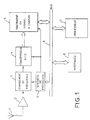
- FIG. 1 represents the general block diagram of a receiver with pseudo-random code. It includes an antenna 1, a low noise amplifier filter assembly 2, a frequency change assembly 3 receiving one (or more) local oscillator signal OL, an analog-digital sampler / converter 4, a signal processing device with n channels 5, a bus 6, a processor 7, interfaces 8 and a frequency synthesis block 9.
- the antenna 1 receives a composite HF signal comprising the signals transmitted by all the satellites in direct view.
- the composite signal is sent to a frequency change assembly 3 which supplies an intermediate frequency signal to the analog / digital sampler / converter 4 as well as a sampling clock signal making it possible to determine the instants at which to be taken. the samples.
- These samples are sent over a signal bus to the signal processing device 5.
- This device associated with the processor 7 comprises n channels, each of which is provided for processing the signals of a particular satellite which is in sight of the receiver. Each channel can therefore process the signals in phase and in quadrature of a satellite and allows the tracking of the carrier and the code assigned to this satellite.
- each channel uses a carrier and code synchronization circuit to lock in phase and in frequency on the carrier signal modulated by the pseudo-random code while maintaining a Doppler shift specific to the satellite considered.
- Each channel therefore maintains a locking with a pseudo-random code generated locally by providing two correlators used in a delay locking loop.
- the device 5 with the processor 7 also performs the demodulation of the data.
- FIG. 1 corresponds to a conventional architecture of a GPS receiver.
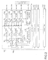
- FIG. 2 is a more detailed diagram of the signal processing device 5.
- the device receives the ACQ samples of the composite signal. It includes n identical Cal to Can channels each assigned to a particular satellite then in view. Only the Cal channel is shown in more detail.
- the correlation signals obtained Sp and Sc are transposed into baseband from a local oscillator signal OL and multipliers 50 for each of the components in phase and in quadrature. These baseband signals are filtered by filters 51A, 52A, 51B, 52B of channels A and B respectively.
- a narrow band filtering for example 1 KHz, is carried out using the filters 56A, 57A, 56B, 57B which deliver the phase I and quadrature Q components of channels A and B respectively (lA, QA, lB, QB). These components are processed by the processor to provide a control signal for the carrier and code numerically controlled oscillators (NCOs).
- NCOs carrier and code numerically controlled oscillators
- the correlation generator supplies, during the acquisition phase, advanced-delayed codes to the two correlators, typically spaced apart from a moment of the code. After acquisition, the correlation generator provides less delayed punctual / advanced codes to the two correlators with reduced spacing to a fraction of a moment.
- a modified correlation generator 58 is used which is shown diagrammatically in FIG. 3.
- This generator first comprises a numerically controlled oscillator 581 controlled by the feedback signal S fb and which controls a pseudo-random code generator 580.
- the codes produced by this generator are sent to a digital delay line with five regularly spaced taps and comprising identical adjustable delay elements 582.
- the outputs of the delay line respectively supply the advanced signals E2, E1, punctual P and delayed L1, L2.
- These signals are combined after weighting by the circuits 583 by an adder 584 to form an arithmetic combination C according to the relation:
- C E2 - 2E1 + 2L1 - L2
- This combination can be sent to the correlator C2 via a switch 585 on the other hand receiving the advanced code E1.
- the correlator C1 can receive by a switch 586 either the point signal P or the delayed signal L.
- the two correlators C1 and C2 operate in a conventional delayed / advanced manner by receiving the codes L1 and E1 via the switches 586 and 585.
- the delays introduced by the elements 582 are adjusted to a value such that the spacing between E1 and L1 is about a code moment.
- switches 585, 586 are set to the position shown in Figure 3 and the spacing [line delay increment] is programmed at a fraction of the time (approximately 0 , 2 code moments for GPS).
- Curve 100 represents the envelope of the position error for a spacing of a C / A code moment
- curve 101 represents the envelope of the position error for correlators with reduced spacing at 0.2 C / A code moment, this as a function of the multiple path delay expressed in C / A code moment.
- the curve 102 relates to the correlation system according to the invention with a spacing of 0.2 C / A code moment. It can be seen that, for the system according to the invention, the position error is almost zero for a multiple path delay of between 0.2 and 0.8 C / A code moment. It is clear that the performance of the system according to the invention (curve 102) is better than that of a known improved correlator with reduced spacing (curve 101).
- the receiver described above can for example be produced with an ASIC circuit for all the circuits up to the output of the channels (output at 1 kHz). Beyond that, tasks are carried out at a low rate allowing the use of a universal microprocessor or a DSP.
Abstract
Description
La présente invention se rapporte à un récepteur de radiolocalisation pour la mesure de distance par code pseudo-aléatoire.The present invention relates to a radiolocation receiver for distance measurement by pseudo-random code.
Des systèmes passifs de positionnement et de navigation tels que le système "Global Positioning system " (GPS) ou son équivalent russe "Global Navigation system" (GLONASS) permettent à un utilisateur de déterminer précisément ses latitude, longitude et altitude ainsi que l'heure à partir de signaux émis par une constellation de satellites. Ces systèmes sont bien connus et sont basés sur la transmission par les satellites de codes pseudo-aléatoires , le récepteur d'un utilisateur ayant à traiter un signal HF composite provenant de ceux de ces satellites en vue directe.Passive positioning and navigation systems such as the Global Positioning System (GPS) or its Russian equivalent "Global Navigation System" (GLONASS) allow a user to precisely determine their latitude, longitude and altitude as well as the time from signals from a constellation of satellites. These systems are well known and are based on the transmission by satellites of pseudo-random codes, the receiver of a user having to process a composite HF signal originating from those of these satellites in direct view.
Chaque satellite transmet des informations à bas débit comprenant des données de navigation telles que l'éphéméride du satellite, le temps courant et des informations d'état, en utilisant un système de codage biphase. Le système GPS utilise un accès multiple par répartition de code et le système GLONASS un accès multiple par répartition en de fréquence.Each satellite transmits low speed information including navigation data such as satellite ephemeris, current time and status information, using a two-phase coding system. The GPS system uses multiple access by code distribution and the GLONASS system uses multiple access by frequency distribution.
Dans les deux cas, un récepteur traite le signal d'un satellite en corrélant le signal composite reçu avec le code pseudo-aléatoire généré localement. La position dans le temps de ce code fournit un moyen de mesurer le temps de transmission du signal depuis le satellite, et par suite de déterminer la position et la vitesse en trois dimensions et le temps précis à partir d'au moins quatre satellites.In both cases, a receiver processes the signal from a satellite by correlating the composite signal received with the locally generated pseudo-random code. The position in time of this code provides a means of measuring the signal transmission time from the satellite, and thereby determining the position and speed in three dimensions and the precise time from at least four satellites.
On mesure habituellement la position temporelle du code pseudo-aléatoire à l'aide d'une boucle de verrouillage de retard (DLL pour "delay lock loop" dans la littérature anglo-saxonne) réalisant la corrélation d code local avancé, ponctuel et retardé avec le signal composite. Les signaux de corrélation, après filtrage et traitement, servent à contrôler la synchronisation du générateur local de code pseudo-aléatoire. En conservant le verrouillage de la boucle, on peut poursuivre le satellite et démoduler les données de navigation superposées au code pseudo-aléatoire.The time position of the pseudo-random code is usually measured using a delay lock loop (DLL for "delay lock loop" in Anglo-Saxon literature) realizing the correlation of local advanced, punctual and delayed code with the composite signal. The correlation signals, after filtering and processing, are used to control the synchronization of the local pseudo-random code generator. By keeping the loop locked, we can continue the satellite and demodulate the navigation data superimposed on the pseudo-random code.
Cependant, de tels systèmes doivent mesurer le temps de la propagation en vue directe et ils sont donc soumis à des distorsions d'origine ionosphérique (retards) ou dues aux trajets multiples par exemple.However, such systems must measure the time of propagation in direct view and they are therefore subject to distortions of ionospheric origin (delays) or due to multipath for example.
Une solution connue consiste à utiliser des corrélateurs avancé-retardé dont l'espacement classique de un moment du code est, après acquisition, réduit à une fraction de moment, ce qui réduit de manière notable l'erreur de poursuite due aux trajets multiples.One known solution consists in using advanced-delayed correlators, the conventional spacing of a moment of the code of which is, after acquisition, reduced to a fraction of a moment, which significantly reduces the tracking error due to the multiple paths.
Cependant cette solution n'est pas totalement satisfaisante car il reste des erreurs résiduelles notables gênantes pour les applications ayant besoin de précision (approche, atterrissage etc...).However, this solution is not completely satisfactory because there are still annoying notable residual errors for applications needing precision (approach, landing, etc.).
Un objet de l'invention est donc un récepteur perfectionné qui permet d'atteindre avec les codes C/A des performances équivalentes à celle d'un récepteur classique à code P, ceci grâce à l'utilisation d'un nouveau type de corrélation quadruple.An object of the invention is therefore an improved receiver which makes it possible to achieve with C / A codes performance equivalent to that of a conventional P-code receiver, this thanks to the use of a new type of quadruple correlation. .
Selon l'invention, il est donc prévu un récepteur à large bande pour la mesure de distance par signaux modulés par des codes pseudo-aléatoires, ledit récepteur démodulant et décodant un signal HF composite incluant plusieurs signaux transmis modulés par des codes pseudo-aléatoires, ledit récepteur comprenant des moyens de changement de fréquence, de filtrage et d'échantillonnage-codage et une pluralité de canaux pour démoduler et décoder chacun un des signaux modulés par des codes pseudo-aléatoires à partir des échantillons fournis par les moyens d'échantillonnage-codage, chaque canal comportant un générateur de code pseudo-aléatoire synchronisé par un signal de contrôle et des moyens de corrélation recevant lesdits échantillons du signal composite et le code fourni par le générateur de code pseudo-aléatoire avec des retards ajustables et fournissant des signaux de corrélation de manière à permettre de déterminer ledit signal de contrôle, ledit récepteur étant caractérisé en ce que lesdits moyens de corrélation comprennent au moins deux corrélateurs, des moyens de combinaison de codes pseudo-aléatoires avancés et retardés pour fournir un signal de quadruple corrélation et des moyens de commutation pour configurer lesdits corrélateurs dans un premier mode d'acquisition comme corrélateurs avancé et retardé et dans un second mode comme corrélateurs ponctuel et combiné quadruple.According to the invention, a broadband receiver is therefore provided for measuring distance by signals modulated by pseudo-random codes, said receiver demodulating and decoding a composite HF signal including several transmitted signals modulated by pseudo-random codes, said receiver comprising frequency change, filtering and sampling-coding means and a plurality of channels for demodulating and decoding each one of the signals modulated by pseudo-random codes from the samples supplied by the sampling means- coding, each channel comprising a pseudo-random code generator synchronized by a control signal and correlation means receiving said samples of the composite signal and the code supplied by the pseudo-random code generator with adjustable delays and supplying signals correlation so as to make it possible to determine said control signal, said reception character being characterized in that said correlation means comprise at least two correlators, means for combining advanced and delayed pseudo-random codes to provide a quadruple correlation signal and switching means for configuring said correlators in a first mode of acquisition as advanced and delayed correlators and in a second mode as point and quadruple combined correlators.
L'invention sera mieux comprise et d'autres caractéristiques et avantages apparaîtront à l'aide de la description ci-après et des dessins joints où :
- la figure 1 est un schéma synoptique général de récepteur à code pseudo-aléatoire ;
- la figure 2 est un schéma de la partie traitement du signal à n canaux;
- la figure 3 est un schéma des moyens de corrélation du récepteur selon l'invention ;
- la figure 4 représente un diagramme temporel de signaux des moyens de corrélation ; et
- la figure 5 représente des courbes d'enveloppe d'erreur de position en fonction du retard multitrajet pour divers espacements de corrélateurs connus et pour le corrélateur selon l'invention.
- Figure 1 is a general block diagram of receiver pseudo-random code;
- FIG. 2 is a diagram of the processing part of the n-channel signal;
- Figure 3 is a diagram of the receiver correlation means according to the invention;
- FIG. 4 represents a time diagram of signals of the correlation means; and
- FIG. 5 represents the position error envelope curves as a function of the multi-path delay for various spacings of known correlators and for the correlator according to the invention.
La figure 1 représente le schéma synoptique général d'un récepteur à code pseudo-aléatoire. Il comprend une antenne 1, un ensemble filtrage amplificateur à faible bruit 2, un ensemble de changement de fréquence 3 recevant un (ou plusieurs) signal d'oscillateur local OL, un échantillonneur/convertisseur analogique-numérique 4, un dispositif de traitement du signal à n canaux 5, un bus 6, un processeur 7, des interfaces 8 et un bloc de synthèse de fréquences 9.FIG. 1 represents the general block diagram of a receiver with pseudo-random code. It includes an
L'antenne 1 reçoit un signal HF composite comprenant les signaux transmis par tous les satellites en vue directe. Le signal composite est envoyé à un ensemble de changement de fréquence 3 qui fournit un signal à fréquence intermédiaire à l'échantillonneur/convertisseur analogique-numérique 4 ainsi qu'un signal d'horloge d'échantillonnage permettant de déterminer les instants auxquels doivent être pris les échantillons. Ces échantillons sont envoyés sur un bus de signal au dispositif de traitement du signal 5. Ce dispositif associé au processeur 7 comprend n canaux dont chacun est prévu pour traiter les signaux d'un satellite particulier qui est en vue du récepteur. Chaque canal peut donc traiter les signaux en phase et en quadrature d'un satellite et permet la poursuite de la porteuse et du code assignés à ce satellite. Comme on le verra ultérieurement, chaque canal utilise un circuit de synchronisation de porteuse et de code pour se verrouiller en phase et en fréquence sur le signal de porteuse modulé par le code pseudo-aléatoire en maintenant un décalage Doppler spécifique au satellite considéré. Chaque canal maintient donc un verrouillage avec un code pseudo-aléatoire généré localement en prévoyant deux corrélateurs utilisés dans une boucle de verrouillage de retard. Le dispositif 5 avec le processeur 7 réalise aussi la démodulation des données.The
Cette description de la figure 1 correspond à une architecture classique de récepteur GPS.This description of FIG. 1 corresponds to a conventional architecture of a GPS receiver.
La figure 2 est un schéma plus détaillé du dispositif de traitement de signal 5. Le dispositif reçoit les échantillons ACQ du signal composite. Il comprend n canaux identiques Cal à Can assignés chacun à un satellite particulier alors en vue. Seul le canal Cal est représenté plus en détail.FIG. 2 is a more detailed diagram of the
Il comporte deux corrélateurs C1 et C2 et un dispositif générateur de corrélation 58 contrôlé par un signal Sfb. Les signaux de corrélation obtenus Sp et Sc sont transposés en bande de base à partir d'un signal d'oscillateur local OL et des multiplieurs 50 pour chacune des composantes en phase et en quadrature. Ces signaux en bande de base sont filtrés par les filtres 51A, 52A, 51B, 52B respectivement des voies A et B. Après élimination de la composante Doppler à l'aide d'un oscillateur à commande numérique 59, commandé par le signal de phase Doppler Pd venant du processeur 7 par le bus 6, et de multiplieurs 53 recevant les sorties sinus S et cosinus C de l'oscillateur 59, on procède à un filtrage à bande étroite, par exemple 1 KHz, à l'aide des filtres 56A, 57A, 56B, 57B qui délivrent respectivement les composantes en phase I et en quadrature Q des voies A et B (lA, QA, lB, QB). Ces composantes sont traitées par le processeur pour fournir un signal de contrôle pour les oscillateurs à commande numérique (NCO) de porteuse et de code.It includes two correlators C1 and C2 and a
Comme on l'a déjà expliqué plus haut, dans les systèmes connus, le générateur de corrélation fournit, pendant la phase d'acquisition, des codes avancé-retardé aux deux corrélateurs, espacés typiquement d'un moment du code. Après acquisition, le générateur de corrélation fournit des codes ponctuel/avancé moins retardé aux deux corrélateurs avec un espacement réduit à une fraction de moment.As already explained above, in known systems, the correlation generator supplies, during the acquisition phase, advanced-delayed codes to the two correlators, typically spaced apart from a moment of the code. After acquisition, the correlation generator provides less delayed punctual / advanced codes to the two correlators with reduced spacing to a fraction of a moment.
Selon l'invention on utilise un générateur de corrélation 58 modifié qui est représenté schématiquement sur la figure 3. Ce générateur comporte d'abord un oscillateur à commande numérique 581 contrôlé par le signal de réaction Sfb et qui pilote un générateur de code pseudo-aléatoire 580. Les codes produits par ce générateur sont envoyés à une ligne à retard numérique à cinq prises régulièrement espacées et comportant des éléments de retard identiques ajustables 582. Les sorties de la ligne à retard fournissent respectivement les signaux avancés E2, E1, ponctuel P et retardés L1, L2. On combine ces signaux après pondération par les circuits 583 par un additionneur 584 pour former une combinaison arithmétique C selon la relation :![]()
![]()
Cette combinaison peut être envoyée au corrélateur C2 par l'intermédiaire d'un commutateur 585 recevant d'autre part le code avancé E1. De même le corrélateur C1 peut recevoir par un commutateur 586 soit le signal ponctuel P soit le signal retardé L.This combination can be sent to the correlator C2 via a
Le fonctionnement est le suivant :The operation is as follows:
En phase d'acquisition, les deux corrélateurs C1 et C2 fonctionnent de manière classique retardé/avancé en recevant les codes L1 et E1 par l'intermédiaire des commutateurs 586 et 585. De plus les retards introduits par les éléments 582 sont ajustés à une valeur telle que l'espacement entre E1 et L1 soit d'environ un moment de code.In the acquisition phase, the two correlators C1 and C2 operate in a conventional delayed / advanced manner by receiving the codes L1 and E1 via the
Quand la boucle de verrouillage de retard (DLL) est verrouillée, on commute les commutateurs 585, 586 sur la position représentée sur la figure 3 et l'espacement [incrément de retard de la ligne] est programmée à une fraction de moment (approximativement 0,2 moment de code pour le GPS).When the delay lock loop (DLL) is locked,
Ceci permet de réduire considérablement l'erreur de position en fonction du retard du multitrajet. Par ailleurs, un autre avantage de la quadruple corrélation selon la relation (1) résulte du fait que la sortie normalisée de la combinaison C a seulement trois états -1, 0 et +1 comme on peut s'en rendre compte à partir des diagrammes de la figure 4. Ceci présente un intérêt certain car la corrélation avec le signal composite reçu ACQ est réalisée très facilement à l'aide de circuits simples à base d'inverseurs et de multiplexeurs sans qu'on ait besoin de multiplieurs.This considerably reduces the position error as a function of the delay of the multipath. In addition, another advantage of the quadruple correlation according to the relation (1) results from the fact that the normalized output of the combination C has only three states -1, 0 and +1 as one can realize it from the diagrams of FIG. 4. This is of certain interest because the correlation with the composite signal received ACQ is very easily achieved using simple circuits based on inverters and multiplexers without the need for multipliers.
Les performances du système de corrélation selon l'invention peuvent être appréciées à partir des courbes de la figure 5.The performance of the correlation system according to the invention can be appreciated from the curves of FIG. 5.
La courbe 100 représente l'enveloppe de l'erreur de position pour un espacement d'un moment de code C/A; la courbe 101 représente l'enveloppe de l'erreur de position pour des corrélateurs à espacement réduit à 0,2 moment de code C/A, ceci en fonction du retard du trajet multiple exprimé en moment de code C/A.
Enfin la courbe 102 est relative au système de corrélation selon l'invention avec un espacement de 0,2 moment de code C/A. On peut voir que, pour le système selon l'invention, l'erreur de position est quasiment nulle pour un retard de trajet multiple compris entre 0,2 et 0,8 moment de code C/A. Il est clair que les performances du système selon l'invention (courbe 102) sont meilleures que celles d'un corrélateur amélioré connu à espacement réduit (courbe 101).Finally, the
Le récepteur décrit ci-dessus peut par exemple être réalisé avec un circuit ASIC pour tous les circuits jusqu'à la sortie des canaux (sortie à 1 kHz). Au-delà, les taches s'effectuent à un rythme bas permettant l'utilisation d'un microprocesseur universel ou d'un DSP.The receiver described above can for example be produced with an ASIC circuit for all the circuits up to the output of the channels (output at 1 kHz). Beyond that, tasks are carried out at a low rate allowing the use of a universal microprocessor or a DSP.
Bien entendu, les exemples décrits ne sont nullement limitatifs de l'invention.Of course, the examples described are in no way limitative of the invention.
Claims (3)
Applications Claiming Priority (2)
| Application Number | Priority Date | Filing Date | Title |
|---|---|---|---|
| FR9511795A FR2739695B1 (en) | 1995-10-06 | 1995-10-06 | BROADBAND RECEIVER WITH DISTANCE MEASUREMENT BY PSEUDO-RANDOM CODE SIGNALS |
| FR9511795 | 1995-10-06 |
Publications (2)
| Publication Number | Publication Date |
|---|---|
| EP0767388A1 true EP0767388A1 (en) | 1997-04-09 |
| EP0767388B1 EP0767388B1 (en) | 2002-01-02 |
Family
ID=9483333
Family Applications (1)
| Application Number | Title | Priority Date | Filing Date |
|---|---|---|---|
| EP96402097A Expired - Lifetime EP0767388B1 (en) | 1995-10-06 | 1996-10-01 | Wideband receiver for measuring range using pseudo random signals |
Country Status (6)
| Country | Link |
|---|---|
| US (1) | US5850420A (en) |
| EP (1) | EP0767388B1 (en) |
| CA (1) | CA2187122C (en) |
| DE (1) | DE69618305T2 (en) |
| ES (1) | ES2167526T3 (en) |
| FR (1) | FR2739695B1 (en) |
Cited By (2)
| Publication number | Priority date | Publication date | Assignee | Title |
|---|---|---|---|---|
| WO2009013314A1 (en) * | 2007-07-24 | 2009-01-29 | Thales | Method for intercepting radioelectric signals and instantaneous broadband compact receiver |
| EP2520949A1 (en) * | 2011-05-05 | 2012-11-07 | Thales | Device for receiving a satellite positioning system including a function for detecting false locking |
Families Citing this family (28)
| Publication number | Priority date | Publication date | Assignee | Title |
|---|---|---|---|---|
| FR2739938B1 (en) * | 1995-10-17 | 1997-11-07 | Sextant Avionique | RECEIVER FOR DETERMINING A POSITION FROM SATELLITE ARRAYS |
| FR2759220B1 (en) * | 1997-01-31 | 1999-04-23 | Sextant Avionique | ANALOG SIGNAL PROCESSING CIRCUIT FOR SATELLITE POSITIONING RECEIVER |
| US6243409B1 (en) | 1997-07-15 | 2001-06-05 | Novatel, Inc. | Global navigation satellite system receiver with blanked-PRN code correlation |
| FR2783929B1 (en) | 1998-09-25 | 2000-12-08 | Sextant Avionique | PROCESS AND DEVICE FOR PROCESSING IN RECEPTION OF A GPS SATELLITE L2 SIGNAL |
| US7777675B2 (en) | 1999-03-05 | 2010-08-17 | Era Systems Corporation | Deployable passive broadband aircraft tracking |
| US7908077B2 (en) | 2003-06-10 | 2011-03-15 | Itt Manufacturing Enterprises, Inc. | Land use compatibility planning software |
| US7739167B2 (en) | 1999-03-05 | 2010-06-15 | Era Systems Corporation | Automated management of airport revenues |
| US7782256B2 (en) | 1999-03-05 | 2010-08-24 | Era Systems Corporation | Enhanced passive coherent location techniques to track and identify UAVs, UCAVs, MAVs, and other objects |
| US8203486B1 (en) | 1999-03-05 | 2012-06-19 | Omnipol A.S. | Transmitter independent techniques to extend the performance of passive coherent location |
| US7889133B2 (en) | 1999-03-05 | 2011-02-15 | Itt Manufacturing Enterprises, Inc. | Multilateration enhancements for noise and operations management |
| US7570214B2 (en) | 1999-03-05 | 2009-08-04 | Era Systems, Inc. | Method and apparatus for ADS-B validation, active and passive multilateration, and elliptical surviellance |
| US8446321B2 (en) | 1999-03-05 | 2013-05-21 | Omnipol A.S. | Deployable intelligence and tracking system for homeland security and search and rescue |
| US7667647B2 (en) | 1999-03-05 | 2010-02-23 | Era Systems Corporation | Extension of aircraft tracking and positive identification from movement areas into non-movement areas |
| GB2351864B (en) | 1999-07-05 | 2004-05-26 | Symmetricom Inc | A receiver for receiving rf pseudo-random encoded signals |
| AU5601800A (en) * | 1999-08-09 | 2001-03-05 | Motorola, Inc. | Adaptive delay lock loop tracking |
| FR2818840B1 (en) * | 2000-12-22 | 2004-06-04 | Thomson Csf | METHOD AND DEVICE FOR HANDLING INTERFERENCE IN SIGNALS RECEIVED BY A SENSOR NETWORK |
| FI111300B (en) * | 2001-05-25 | 2003-06-30 | Nokia Corp | A method of controlling the operation of a positioning receiver and an electronic device |
| FR2829638B1 (en) * | 2001-09-07 | 2003-12-12 | Thales Sa | METHOD AND DEVICE FOR ANTI-INTERFERENCE, IN RECEPTION, OF A BROADBAND RADIOELECTRIC SIGNAL |
| FR2832878B1 (en) * | 2001-11-27 | 2004-02-13 | Thales Sa | METHOD OF DETECTION AND TREATMENT OF PULSED SIGNALS IN A RADIO-ELECTRIC SIGNAL |
| FR2833784B1 (en) * | 2001-12-18 | 2004-02-13 | Thales Sa | ANTI-JAMMING METHOD FOR A SPREAD SPECTRUM RADIO SIGNAL RECEIVER |
| FR2857101B1 (en) * | 2003-07-01 | 2007-01-05 | Thales Sa | METHOD FOR REJECTING INTERFERENCES WHICH DISRUPT THE RECEPTION OF A TRANSMISSION SIGNAL AND DEVICE |
| FR2867619B1 (en) * | 2004-03-12 | 2006-06-23 | Thales Sa | FREQUENCY OFFSET DEVICE IN A PULSED LASER SOURCE OPTICAL PATH |
| US7636397B2 (en) * | 2005-09-07 | 2009-12-22 | Mclaughlin Michael | Method and apparatus for transmitting and receiving convolutionally coded data for use with combined binary phase shift keying (BPSK) modulation and pulse position modulation (PPM) |
| US7965227B2 (en) | 2006-05-08 | 2011-06-21 | Era Systems, Inc. | Aircraft tracking using low cost tagging as a discriminator |
| RU2486672C1 (en) * | 2012-02-17 | 2013-06-27 | Федеральное государственное бюджетное образовательное учреждение высшего профессионального образования "Ижевский государственный технический университет имени М.Т. Калашникова" | Method of monitoring broadband signal delay and apparatus for realising said method |
| FR3011087B1 (en) | 2013-09-24 | 2017-05-05 | Thales Sa | METHOD FOR ACQUIRING A RADIONAVIGATION SATELLITE SIGNAL AND SATELLITE RADIONAVIGATION RECEIVER USING THE SAME |
| CN106569182B (en) * | 2016-11-02 | 2018-11-30 | 西安电子科技大学 | Phase-coded signal carrier frequency estimation method based on minimum entropy |
| CN117269998B (en) * | 2023-11-20 | 2024-02-02 | 北京凯芯微科技有限公司 | GNSS receiver and noise estimation method |
Citations (3)
| Publication number | Priority date | Publication date | Assignee | Title |
|---|---|---|---|---|
| GB2189969A (en) * | 1986-04-30 | 1987-11-04 | Multitone Electronics Plc | Code tracking circuits for spread-spectrum receivers |
| DE3806394A1 (en) * | 1988-02-29 | 1989-09-07 | Ant Nachrichtentech | Method and circuit arrangement for controlling the phase angle between a generated code and a received code contained in a received spread-spectrum signal |
| EP0552975A2 (en) * | 1992-01-24 | 1993-07-28 | Novatel Communications Ltd. | A pseudorandom noise ranging receiver which compensates for multipath distortion by dynamically adjusting the time delay spacing between early and late correlators |
Family Cites Families (7)
| Publication number | Priority date | Publication date | Assignee | Title |
|---|---|---|---|---|
| US4550414A (en) * | 1983-04-12 | 1985-10-29 | Charles Stark Draper Laboratory, Inc. | Spread spectrum adaptive code tracker |
| US5253268A (en) * | 1990-05-24 | 1993-10-12 | Cylink Corporation | Method and apparatus for the correlation of sample bits of spread spectrum radio signals |
| US5390207A (en) * | 1990-11-28 | 1995-02-14 | Novatel Communications Ltd. | Pseudorandom noise ranging receiver which compensates for multipath distortion by dynamically adjusting the time delay spacing between early and late correlators |
| US5101416A (en) * | 1990-11-28 | 1992-03-31 | Novatel Comunications Ltd. | Multi-channel digital receiver for global positioning system |
| FR2679096B1 (en) * | 1991-07-12 | 1996-06-07 | Seb Sa | HEATING ASSEMBLY FOR ELECTRIC HEATING APPARATUS, ESPECIALLY KETTLE. |
| US5414729A (en) * | 1992-01-24 | 1995-05-09 | Novatel Communications Ltd. | Pseudorandom noise ranging receiver which compensates for multipath distortion by making use of multiple correlator time delay spacing |
| US5600670A (en) * | 1994-12-21 | 1997-02-04 | Trimble Navigation, Ltd. | Dynamic channel allocation for GPS receivers |
-
1995
- 1995-10-06 FR FR9511795A patent/FR2739695B1/en not_active Expired - Lifetime
-
1996
- 1996-09-27 US US08/722,312 patent/US5850420A/en not_active Expired - Lifetime
- 1996-10-01 DE DE69618305T patent/DE69618305T2/en not_active Expired - Fee Related
- 1996-10-01 ES ES96402097T patent/ES2167526T3/en not_active Expired - Lifetime
- 1996-10-01 EP EP96402097A patent/EP0767388B1/en not_active Expired - Lifetime
- 1996-10-04 CA CA002187122A patent/CA2187122C/en not_active Expired - Fee Related
Patent Citations (3)
| Publication number | Priority date | Publication date | Assignee | Title |
|---|---|---|---|---|
| GB2189969A (en) * | 1986-04-30 | 1987-11-04 | Multitone Electronics Plc | Code tracking circuits for spread-spectrum receivers |
| DE3806394A1 (en) * | 1988-02-29 | 1989-09-07 | Ant Nachrichtentech | Method and circuit arrangement for controlling the phase angle between a generated code and a received code contained in a received spread-spectrum signal |
| EP0552975A2 (en) * | 1992-01-24 | 1993-07-28 | Novatel Communications Ltd. | A pseudorandom noise ranging receiver which compensates for multipath distortion by dynamically adjusting the time delay spacing between early and late correlators |
Cited By (5)
| Publication number | Priority date | Publication date | Assignee | Title |
|---|---|---|---|---|
| WO2009013314A1 (en) * | 2007-07-24 | 2009-01-29 | Thales | Method for intercepting radioelectric signals and instantaneous broadband compact receiver |
| FR2919447A1 (en) * | 2007-07-24 | 2009-01-30 | Thales Sa | METHOD OF INTERCEPTING RADIO SIGNALS AND INSTANT BROADBAND COMPACT RECEIVER |
| EP2520949A1 (en) * | 2011-05-05 | 2012-11-07 | Thales | Device for receiving a satellite positioning system including a function for detecting false locking |
| FR2974914A1 (en) * | 2011-05-05 | 2012-11-09 | Thales Sa | DEVICE FOR RECEIVING A SATELLITE POSITIONING SYSTEM COMPRISING A FUNCTION FOR DETECTING FALSE ATTACHMENTS |
| US8675713B2 (en) | 2011-05-05 | 2014-03-18 | Thales | Satellite-based positioning system reception device comprising a function for detecting false lock-ons |
Also Published As
| Publication number | Publication date |
|---|---|
| ES2167526T3 (en) | 2002-05-16 |
| DE69618305D1 (en) | 2002-02-07 |
| FR2739695B1 (en) | 1997-11-07 |
| FR2739695A1 (en) | 1997-04-11 |
| DE69618305T2 (en) | 2002-08-08 |
| CA2187122C (en) | 2006-07-04 |
| US5850420A (en) | 1998-12-15 |
| CA2187122A1 (en) | 1997-04-07 |
| EP0767388B1 (en) | 2002-01-02 |
Similar Documents
| Publication | Publication Date | Title |
|---|---|---|
| EP0767388B1 (en) | Wideband receiver for measuring range using pseudo random signals | |
| US5410750A (en) | Interference suppressor for a radio receiver | |
| JP3262585B2 (en) | Digital Processing Technology for Global Positioning System Receiver | |
| EP0438199B1 (en) | Radio receiver | |
| US6259401B1 (en) | Global positioning system receiver with improved multipath signal rejection | |
| US5459473A (en) | GPS receiver | |
| US5805108A (en) | Apparatus and method for processing multiple frequencies in satellite navigation systems | |
| US5621416A (en) | Optimized processing of signals for enhanced cross-correlation in a satellite positioning system receiver | |
| CA2257351C (en) | Satellite signal receiver with position extrapolation filter | |
| JPH09505404A (en) | Pseudo Random Noise Ranging Receiver Compensating Multipath Distortion by Using Multicorrelator Time Delay Intervals | |
| US20220276389A1 (en) | Satellite navigation receiver for acquisition of gnss signals | |
| EP2095150B1 (en) | Method and device for receiving a boc modulation radio-navigation signal | |
| FR2783929A1 (en) | PROCESS AND DEVICE FOR PROCESSING IN RECEPTION OF A GPS SATELLITE L2 SIGNAL | |
| WO2023129763A1 (en) | Satellite navigation receiver with aggregate channel digital baseband processing | |
| WO2005006012A1 (en) | Method and device for the demodulation of satellite radio navigation signals | |
| US6130908A (en) | Code multipath analyzer using weighted or modified correlations | |
| JP3956722B2 (en) | Matched filter device, correlation detection method, and receiver | |
| Phyo et al. | Implementation and analysis of signal tracking loops for software defined GPS receiver | |
| WO2021255386A2 (en) | Receiver of radionavigation signals comprising a computer of a correlation power indicator | |
| EP0987559A2 (en) | Direct sampling global positioning system (GPS) receiver | |
| US20040240530A1 (en) | Multipath discriminator module for a navigation system | |
| EP2851707B1 (en) | Method of satellite radio navigation signal acquisition and satellite radio navigation receiver implementing the method |
Legal Events
| Date | Code | Title | Description |
|---|---|---|---|
| PUAI | Public reference made under article 153(3) epc to a published international application that has entered the european phase |
Free format text: ORIGINAL CODE: 0009012 |
|
| AK | Designated contracting states |
Kind code of ref document: A1 Designated state(s): DE ES GB |
|
| 17P | Request for examination filed |
Effective date: 19971004 |
|
| RAP1 | Party data changed (applicant data changed or rights of an application transferred) |
Owner name: THOMSON-CSF SEXTANT |
|
| 17Q | First examination report despatched |
Effective date: 20000530 |
|
| GRAG | Despatch of communication of intention to grant |
Free format text: ORIGINAL CODE: EPIDOS AGRA |
|
| GRAG | Despatch of communication of intention to grant |
Free format text: ORIGINAL CODE: EPIDOS AGRA |
|
| GRAH | Despatch of communication of intention to grant a patent |
Free format text: ORIGINAL CODE: EPIDOS IGRA |
|
| RAP1 | Party data changed (applicant data changed or rights of an application transferred) |
Owner name: THALES AVIONICS S.A. |
|
| GRAH | Despatch of communication of intention to grant a patent |
Free format text: ORIGINAL CODE: EPIDOS IGRA |
|
| GRAA | (expected) grant |
Free format text: ORIGINAL CODE: 0009210 |
|
| REG | Reference to a national code |
Ref country code: GB Ref legal event code: IF02 |
|
| AK | Designated contracting states |
Kind code of ref document: B1 Designated state(s): DE ES GB |
|
| REF | Corresponds to: |
Ref document number: 69618305 Country of ref document: DE Date of ref document: 20020207 |
|
| GBT | Gb: translation of ep patent filed (gb section 77(6)(a)/1977) |
Effective date: 20020325 |
|
| REG | Reference to a national code |
Ref country code: ES Ref legal event code: FG2A Ref document number: 2167526 Country of ref document: ES Kind code of ref document: T3 |
|
| PG25 | Lapsed in a contracting state [announced via postgrant information from national office to epo] |
Ref country code: ES Free format text: LAPSE BECAUSE OF NON-PAYMENT OF DUE FEES Effective date: 20021002 |
|
| PLBE | No opposition filed within time limit |
Free format text: ORIGINAL CODE: 0009261 |
|
| STAA | Information on the status of an ep patent application or granted ep patent |
Free format text: STATUS: NO OPPOSITION FILED WITHIN TIME LIMIT |
|
| 26N | No opposition filed | ||
| REG | Reference to a national code |
Ref country code: ES Ref legal event code: FD2A Effective date: 20031112 |
|
| PGFP | Annual fee paid to national office [announced via postgrant information from national office to epo] |
Ref country code: DE Payment date: 20060928 Year of fee payment: 11 |
|
| PG25 | Lapsed in a contracting state [announced via postgrant information from national office to epo] |
Ref country code: DE Free format text: LAPSE BECAUSE OF NON-PAYMENT OF DUE FEES Effective date: 20080501 |
|
| PGFP | Annual fee paid to national office [announced via postgrant information from national office to epo] |
Ref country code: GB Payment date: 20130925 Year of fee payment: 18 |
|
| GBPC | Gb: european patent ceased through non-payment of renewal fee |
Effective date: 20141001 |
|
| PG25 | Lapsed in a contracting state [announced via postgrant information from national office to epo] |
Ref country code: GB Free format text: LAPSE BECAUSE OF NON-PAYMENT OF DUE FEES Effective date: 20141001 |