EP0767081A1 - Wärmerückgewinnungsanlage aus Fahrzeugabgasen - Google Patents
Wärmerückgewinnungsanlage aus Fahrzeugabgasen Download PDFInfo
- Publication number
- EP0767081A1 EP0767081A1 EP95402232A EP95402232A EP0767081A1 EP 0767081 A1 EP0767081 A1 EP 0767081A1 EP 95402232 A EP95402232 A EP 95402232A EP 95402232 A EP95402232 A EP 95402232A EP 0767081 A1 EP0767081 A1 EP 0767081A1
- Authority
- EP
- European Patent Office
- Prior art keywords
- exchanger
- exhaust gases
- fluid
- capacity
- chamber
- Prior art date
- Legal status (The legal status is an assumption and is not a legal conclusion. Google has not performed a legal analysis and makes no representation as to the accuracy of the status listed.)
- Granted
Links
Images

Classifications
-
- B—PERFORMING OPERATIONS; TRANSPORTING
- B60—VEHICLES IN GENERAL
- B60H—ARRANGEMENTS OF HEATING, COOLING, VENTILATING OR OTHER AIR-TREATING DEVICES SPECIALLY ADAPTED FOR PASSENGER OR GOODS SPACES OF VEHICLES
- B60H1/00—Heating, cooling or ventilating [HVAC] devices
- B60H1/02—Heating, cooling or ventilating [HVAC] devices the heat being derived from the propulsion plant
- B60H1/14—Heating, cooling or ventilating [HVAC] devices the heat being derived from the propulsion plant otherwise than from cooling liquid of the plant, e.g. heat from the grease oil, the brakes, the transmission unit
- B60H1/18—Heating, cooling or ventilating [HVAC] devices the heat being derived from the propulsion plant otherwise than from cooling liquid of the plant, e.g. heat from the grease oil, the brakes, the transmission unit the air being heated from the plant exhaust gases
- B60H1/20—Heating, cooling or ventilating [HVAC] devices the heat being derived from the propulsion plant otherwise than from cooling liquid of the plant, e.g. heat from the grease oil, the brakes, the transmission unit the air being heated from the plant exhaust gases using an intermediate heat-transferring medium
-
- B—PERFORMING OPERATIONS; TRANSPORTING
- B60—VEHICLES IN GENERAL
- B60H—ARRANGEMENTS OF HEATING, COOLING, VENTILATING OR OTHER AIR-TREATING DEVICES SPECIALLY ADAPTED FOR PASSENGER OR GOODS SPACES OF VEHICLES
- B60H1/00—Heating, cooling or ventilating [HVAC] devices
- B60H1/02—Heating, cooling or ventilating [HVAC] devices the heat being derived from the propulsion plant
- B60H1/025—Heating, cooling or ventilating [HVAC] devices the heat being derived from the propulsion plant from both the cooling liquid and the exhaust gases of the propulsion plant
-
- F—MECHANICAL ENGINEERING; LIGHTING; HEATING; WEAPONS; BLASTING
- F01—MACHINES OR ENGINES IN GENERAL; ENGINE PLANTS IN GENERAL; STEAM ENGINES
- F01P—COOLING OF MACHINES OR ENGINES IN GENERAL; COOLING OF INTERNAL-COMBUSTION ENGINES
- F01P11/00—Component parts, details, or accessories not provided for in, or of interest apart from, groups F01P1/00 - F01P9/00
- F01P11/02—Liquid-coolant filling, overflow, venting, or draining devices
- F01P11/029—Expansion reservoirs
-
- F—MECHANICAL ENGINEERING; LIGHTING; HEATING; WEAPONS; BLASTING
- F01—MACHINES OR ENGINES IN GENERAL; ENGINE PLANTS IN GENERAL; STEAM ENGINES
- F01P—COOLING OF MACHINES OR ENGINES IN GENERAL; COOLING OF INTERNAL-COMBUSTION ENGINES
- F01P2050/00—Applications
- F01P2050/02—Marine engines
- F01P2050/06—Marine engines using liquid-to-liquid heat exchangers
-
- F—MECHANICAL ENGINEERING; LIGHTING; HEATING; WEAPONS; BLASTING
- F01—MACHINES OR ENGINES IN GENERAL; ENGINE PLANTS IN GENERAL; STEAM ENGINES
- F01P—COOLING OF MACHINES OR ENGINES IN GENERAL; COOLING OF INTERNAL-COMBUSTION ENGINES
- F01P2060/00—Cooling circuits using auxiliaries
- F01P2060/08—Cabin heater
-
- F—MECHANICAL ENGINEERING; LIGHTING; HEATING; WEAPONS; BLASTING
- F01—MACHINES OR ENGINES IN GENERAL; ENGINE PLANTS IN GENERAL; STEAM ENGINES
- F01P—COOLING OF MACHINES OR ENGINES IN GENERAL; COOLING OF INTERNAL-COMBUSTION ENGINES
- F01P2060/00—Cooling circuits using auxiliaries
- F01P2060/16—Outlet manifold
-
- F—MECHANICAL ENGINEERING; LIGHTING; HEATING; WEAPONS; BLASTING
- F01—MACHINES OR ENGINES IN GENERAL; ENGINE PLANTS IN GENERAL; STEAM ENGINES
- F01P—COOLING OF MACHINES OR ENGINES IN GENERAL; COOLING OF INTERNAL-COMBUSTION ENGINES
- F01P2060/00—Cooling circuits using auxiliaries
- F01P2060/18—Heater
-
- F—MECHANICAL ENGINEERING; LIGHTING; HEATING; WEAPONS; BLASTING
- F01—MACHINES OR ENGINES IN GENERAL; ENGINE PLANTS IN GENERAL; STEAM ENGINES
- F01P—COOLING OF MACHINES OR ENGINES IN GENERAL; COOLING OF INTERNAL-COMBUSTION ENGINES
- F01P3/00—Liquid cooling
- F01P3/20—Cooling circuits not specific to a single part of engine or machine
Definitions
- the invention relates to a device making it possible to recover the heat from the exhaust gases of motor vehicles and to restore it either to the heating system of the passenger compartment of said vehicles, or to the cooling circuit of their engine.
- an intermediate phase change fluid such as water.
- This fluid is vaporized, by heat exchange with the exhaust gases, in a vaporizer exchanger, and condensed, in a condenser exchanger, in contact with the fluid to be heated.
- Such a device is described, for example, in document EP-B-189 624.
- the device described in this document comprises a device for absorbing heat placed in the exhaust duct of a vehicle and a device for restitution heat disposed in the heating duct of the passenger compartment of said vehicle.
- These two devices are connected by a circuit for the passage of the steam circulating from the absorption device to the device for the return of heat and a return circuit for the condensed liquid placed between a collector of this liquid, disposed below the part of heat recovery, and the heat absorbing device.
- This return circuit also includes a valve for adjusting the quantity of fluid returned to said absorption device, as a function of the temperature of the air downstream of the heat release device. It is thus possible to regulate the intake of calories from the exhaust according to the needs of the heating system.
- the object of the present invention is to remedy the drawbacks described above and thus to give the system perfect job security and constant adaptation of the power exchanged to instantaneous needs for recovery energy.
- a device making it possible to recover the heat from the exhaust gases of a motor vehicle, circulating in a pipe element, and to restore it to a fluid circuit at lower temperature of said vehicle of the type consisting of a closed circuit containing an intermediate heat transfer fluid and comprising a vaporizer exchanger, in thermal contact with the exhaust gases and a condenser exchanger, in thermal contact with the fluid to be heated, connected by circulation pipes of the heat transfer fluid in phase vapor and / or liquid.
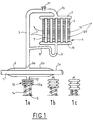
- FIG. 1 shows a pipe element 1 in which the exhaust gases of a motor vehicle engine circulate.
- This element 1 is surrounded by an annular chamber forming a sealed enclosure 2 whose wall 2 a is, for example welded to the outer wall 1 a of the pipe element.
- a conduit 3 opens at one of its ends 3 a into said annular chamber 2 and at its other end 3 b into one of the water boxes 7 of a radiator 4.
- This radiator conventionally comprises a bundle of tubes 5 lined with fins 6 and connected between the water box 7 and a second water box 10.
- This second water box is connected to the conduit 3 by a channel 8 provided with a siphon 9.
- This radiator is, for example, installed in the air flow F of the heating duct (not shown) of the passenger compartment of the vehicle.
- the device also comprises a deformable capacity 13 connected by a conduit 12 to the sealed chamber 2 surrounding the exhaust conduit.
- a spring 14 is placed in abutment between the wall 13 a of the capacity opposite the entry of the conduit 12 and an element S of the structure of the vehicle. Said spring is arranged so as to oppose the expansion of the capsule.
- the assembly thus formed closed and sealed contains a small amount of a two-phase fluid, for example water which can be added with an agent (alcohol, glycol, in particular) capable of preventing its freezing.
- a two-phase fluid for example water which can be added with an agent (alcohol, glycol, in particular) capable of preventing its freezing.
- the exhaust gases enter the pipe 1 at high temperature and tend to heat the liquid contained in the chamber 2 and bring it to a temperature sufficient to create the boil.
- This boiling temperature for a given fluid, depends on the pressure prevailing in the enclosure where it occurs. A more or less high vacuum obtained by extracting, by the valve 11, before closing the circuit, the air contained in the device, makes it possible to lower this temperature.
- the fluid vaporizes and its vapor is released towards the upper part of the chamber 2. This vapor is then brought, by the conduit 3, to the radiator 4. The vapor then bathes the tubes 5 of this exchanger to which it transmits its latent heat of vaporization, which is returned, by the fins 6, to the air which circulates through the radiator.
- the level of liquid contained in the annular chamber 2 then drops, reducing the active wetted surface for exchange with the exhaust gases circulating in the pipe 1.
- the system thus ensures, in addition to a perfect adaptation to the needs of exchanged power, total operational safety. In fact, in no case can the vapor pressure rise in the enclosure beyond the setting pressure of the compensating spring.
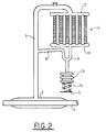
- the deformable capacity 13 is connected in the lower part of the siphon 9 formed in the condensate recovery channel 8 connected to the water box 10 of the radiator outlet 4.
- the expansion of the capacity 13 is limited by the calibration spring 14, bearing on an element S of the structure.
- the deformable capacity although no longer connecting to the low point of the device, makes it possible to accumulate a greater or lesser part of the condensed liquid, depending on the pressure prevailing in the closed enclosure, by recovering this liquid as soon as possible. the outlet of the condensing element.
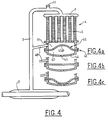
- FIG. 3 presents a simplified variant of the embodiment of FIG. 1.
- a single conduit 30 ensures both the routing of the vapors coming from the annular chamber 2 towards the radiator 4 and the return of the condensed fluid in said radiator to chamber 2.
- the conduit 30 is connected between the water box 10 leaving the radiator 4 and said vaporization chamber 2.
- the deformable capacity is integrated into the radiator outlet water box.
- said water box 40 is separated into two chambers 41, 42 by a deformable membrane 45.
- the return channel 48 of the condensed fluid is connected, on one side, to the conduit 3 for conveying the vapors, thus than previously, and on the other side in the upper part of the upper chamber 41. It is also in this chamber that the bundle of tubes 5 of the radiator opens.
- the lower chamber 42 is delimited by the partition 45 and by the lower wall 44 of the water box 40. This wall 44 is pierced with an orifice 43 for venting the aforementioned chamber.
- the membrane 45 has a profile whose convexity 45 a is oriented in the direction of the upper chamber 41, so as to reduce the internal volume of said chamber. As long as the heat inputs recovered from the exhaust gases are completely absorbed by the condenser exchanger, the condensates returning to the annular enclosure 2 circulate through the channel 48 and the conduit 3.
- the membrane 45 gradually deforms, as shown in FIGS. 4b and 4c. At the end of this deformation, the convexity 45 has said membrane is facing the bottom wall 43 of the box 40.
- the volume of the lower chamber 41 is thus increased, and forms a holding capacity whose level is located below the mouth of the exchanger outlet channel 48. In this way, the condensates produced in this exchanger accumulate in priority in the volume thus created, instead of returning to the annular enclosure.
- the upper chamber 41 can be filled with a material capable of retaining the liquid accumulated in said chamber as long as the membrane 45 remains subject to the influence of pressure.
- the embodiments described so far refer to applications of the invention intended to heat the air in the passenger compartment of a vehicle.
- the device can also be used to heat the cooling circuit of the engine of this vehicle and thus allow the temperature to rise faster.
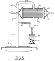
- FIG. 5 An example of such an arrangement is provided in FIG. 5. It can be seen that the circuit is basically identical to that of FIG. 1, only the condenser exchanger is different. Indeed, it is a question here of transferring the energy taken from the exhaust gases no longer to a gaseous fluid but to a liquid.
- the exchanger 54 is therefore installed on a pipe 51 of the engine cooling circuit.
- the coolant L circulates in tubes 55 installed between the water inlet box 52 and the outlet box 53.
- the vapor coming from the annular enclosure 2 is directly sent to the upper part of the exchanger, it flows between the tubes 5, and comes out at the bottom of the exchanger.
- the operation of the system is, moreover, identical to the previous cases.
- the pipe element 1 around which the annular enclosure 2 is installed may be part of the vehicle exhaust line or even part of the exhaust gas recycling duct, a certain amount of which is reintroduced into the intake duct to reduce the discharge of harmful gases into the atmosphere.
- the vaporization enclosure could no longer be installed around but inside the exhaust gas pipe.
Priority Applications (2)
| Application Number | Priority Date | Filing Date | Title |
|---|---|---|---|
| DE1995624414 DE69524414T2 (de) | 1995-10-06 | 1995-10-06 | Wärmerückgewinnungsanlage aus Fahrzeugabgasen |
| EP19950402232 EP0767081B1 (de) | 1995-10-06 | 1995-10-06 | Wärmerückgewinnungsanlage aus Fahrzeugabgasen |
Applications Claiming Priority (1)
| Application Number | Priority Date | Filing Date | Title |
|---|---|---|---|
| EP19950402232 EP0767081B1 (de) | 1995-10-06 | 1995-10-06 | Wärmerückgewinnungsanlage aus Fahrzeugabgasen |
Publications (2)
| Publication Number | Publication Date |
|---|---|
| EP0767081A1 true EP0767081A1 (de) | 1997-04-09 |
| EP0767081B1 EP0767081B1 (de) | 2001-12-05 |
Family
ID=8221533
Family Applications (1)
| Application Number | Title | Priority Date | Filing Date |
|---|---|---|---|
| EP19950402232 Expired - Lifetime EP0767081B1 (de) | 1995-10-06 | 1995-10-06 | Wärmerückgewinnungsanlage aus Fahrzeugabgasen |
Country Status (2)
| Country | Link |
|---|---|
| EP (1) | EP0767081B1 (de) |
| DE (1) | DE69524414T2 (de) |
Cited By (2)
| Publication number | Priority date | Publication date | Assignee | Title |
|---|---|---|---|---|
| US10428713B2 (en) | 2017-09-07 | 2019-10-01 | Denso International America, Inc. | Systems and methods for exhaust heat recovery and heat storage |
| JP2020044896A (ja) * | 2018-09-17 | 2020-03-26 | マツダ株式会社 | 車両用の空調装置 |
Families Citing this family (1)
| Publication number | Priority date | Publication date | Assignee | Title |
|---|---|---|---|---|
| DE102017105612A1 (de) | 2017-03-16 | 2018-09-20 | Volkswagen Aktiengesellschaft | Antriebssystem und Kraftfahrzeug |
Citations (6)
| Publication number | Priority date | Publication date | Assignee | Title |
|---|---|---|---|---|
| FR687423A (fr) * | 1928-12-31 | 1930-08-08 | Dispositif de chauffage pour véhicules mus par moteurs à combustion | |
| US1986893A (en) * | 1929-11-04 | 1935-01-08 | Harold S Hasbrouck | Steam heater for motor vehicles |
| DE2551911A1 (de) * | 1975-11-19 | 1977-06-02 | Daimler Benz Ag | Heizvorrichtung |
| EP0189624A2 (de) * | 1985-01-30 | 1986-08-06 | Sanoh Kogyo Kabushiki Kaisha | Heizungssystem für die Innenräume von Kraftfahrzeugen |
| EP0496942A1 (de) * | 1991-01-31 | 1992-08-05 | Firma Carl Freudenberg | Verdampfungsgekühlte Verbrennungskraftmaschine |
| FR2718491A1 (fr) * | 1994-04-08 | 1995-10-13 | Robin Roger Claude | Dispositif de récupération d'énergie sur échappement de moteurs thermiques. |
-
1995
- 1995-10-06 DE DE1995624414 patent/DE69524414T2/de not_active Expired - Fee Related
- 1995-10-06 EP EP19950402232 patent/EP0767081B1/de not_active Expired - Lifetime
Patent Citations (7)
| Publication number | Priority date | Publication date | Assignee | Title |
|---|---|---|---|---|
| FR687423A (fr) * | 1928-12-31 | 1930-08-08 | Dispositif de chauffage pour véhicules mus par moteurs à combustion | |
| US1986893A (en) * | 1929-11-04 | 1935-01-08 | Harold S Hasbrouck | Steam heater for motor vehicles |
| DE2551911A1 (de) * | 1975-11-19 | 1977-06-02 | Daimler Benz Ag | Heizvorrichtung |
| EP0189624A2 (de) * | 1985-01-30 | 1986-08-06 | Sanoh Kogyo Kabushiki Kaisha | Heizungssystem für die Innenräume von Kraftfahrzeugen |
| EP0189624B1 (de) | 1985-01-30 | 1989-06-07 | Sanoh Kogyo Kabushiki Kaisha | Heizungssystem für die Innenräume von Kraftfahrzeugen |
| EP0496942A1 (de) * | 1991-01-31 | 1992-08-05 | Firma Carl Freudenberg | Verdampfungsgekühlte Verbrennungskraftmaschine |
| FR2718491A1 (fr) * | 1994-04-08 | 1995-10-13 | Robin Roger Claude | Dispositif de récupération d'énergie sur échappement de moteurs thermiques. |
Cited By (2)
| Publication number | Priority date | Publication date | Assignee | Title |
|---|---|---|---|---|
| US10428713B2 (en) | 2017-09-07 | 2019-10-01 | Denso International America, Inc. | Systems and methods for exhaust heat recovery and heat storage |
| JP2020044896A (ja) * | 2018-09-17 | 2020-03-26 | マツダ株式会社 | 車両用の空調装置 |
Also Published As
| Publication number | Publication date |
|---|---|
| EP0767081B1 (de) | 2001-12-05 |
| DE69524414T2 (de) | 2002-08-08 |
| DE69524414D1 (de) | 2002-01-17 |
Similar Documents
| Publication | Publication Date | Title |
|---|---|---|
| EP0832411B1 (de) | Wärmeübertragungskreislauf mit kapillaren pumpen | |
| EP2032440B1 (de) | Passives kapillargepumptes diphasisches flüssigkeitskreis-wärmesteuerungsgerät mit wärmeleistung | |
| FR2899960A1 (fr) | Dispositif de recuperation de chaleur d'echappement | |
| FR2699365A1 (fr) | Système de dissipation de l'énergie calorifique dégagée par un composant électronique. | |
| FR3094070A1 (fr) | Dispositif et procédé de stockage et de fourniture de carburant fluide. | |
| WO2017103449A1 (fr) | Pack de batterie refroidit par un matériau a changement de phase a pression constante | |
| EP2108910B1 (de) | Innere wärmetauscher umfassend ein wärmespeichermittel und kreislauf mit einem solchen wärmetauscher | |
| FR2723187A1 (fr) | Systeme de transfert d'energie entre une source chaude et une source froide | |
| EP0550748B1 (de) | Kaelteerzeugungsanlage mittels einer reaktion zwischen einem festen koerper und einem gas, und von kuehlmitteln versehener reaktor | |
| EP0767081B1 (de) | Wärmerückgewinnungsanlage aus Fahrzeugabgasen | |
| WO1999018387A1 (fr) | Procede et installation de remplissage d'un reservoir sous pression | |
| FR2915520A1 (fr) | Ensemble moteur comprenant un ou plusieurs caloducs pour le refroidissement d'un compresseur haute pression | |
| FR2718491A1 (fr) | Dispositif de récupération d'énergie sur échappement de moteurs thermiques. | |
| WO2011045507A1 (fr) | Dispositif de climatisation perfectionne | |
| JP2007024424A (ja) | 排熱回収装置、および排熱回収装置の冷媒充填方法 | |
| CA1227978A (fr) | Systeme de chauffage solaire par changement de phases | |
| FR2682175A1 (fr) | Vaporiseur de gaz liquefie protege contre les consequences du gel d'un fluide d'apport calorifique. | |
| FR2801643A1 (fr) | Dispositif de detente de gaz liquefie a element de vaporisation separe | |
| BE882280A (fr) | Dispositif et procede de transfert de chaleur | |
| FR2510183A1 (fr) | Recuperateur d'energie des moteurs a combustion interne | |
| EP1451463B1 (de) | Thermostatregler für eine brennkraftmaschine mit wasserkühlung | |
| EP2981781A1 (de) | Wärmerohr mit abgeschirmtem gasstecker | |
| WO2013000547A1 (fr) | Circuit de fluide refrigerant avec deux moyens de stockage du fluide refrigerant | |
| FR2721655A1 (fr) | Dispositif de refroidissement par évaporation pour moteur à combustion interne. | |
| FR2701549A1 (fr) | Climatiseur tournant. |
Legal Events
| Date | Code | Title | Description |
|---|---|---|---|
| PUAI | Public reference made under article 153(3) epc to a published international application that has entered the european phase |
Free format text: ORIGINAL CODE: 0009012 |
|
| AK | Designated contracting states |
Kind code of ref document: A1 Designated state(s): DE FR GB IT |
|
| 17P | Request for examination filed |
Effective date: 19970801 |
|
| 17Q | First examination report despatched |
Effective date: 19990223 |
|
| GRAG | Despatch of communication of intention to grant |
Free format text: ORIGINAL CODE: EPIDOS AGRA |
|
| GRAG | Despatch of communication of intention to grant |
Free format text: ORIGINAL CODE: EPIDOS AGRA |
|
| GRAH | Despatch of communication of intention to grant a patent |
Free format text: ORIGINAL CODE: EPIDOS IGRA |
|
| GRAH | Despatch of communication of intention to grant a patent |
Free format text: ORIGINAL CODE: EPIDOS IGRA |
|
| GRAA | (expected) grant |
Free format text: ORIGINAL CODE: 0009210 |
|
| AK | Designated contracting states |
Kind code of ref document: B1 Designated state(s): DE FR GB IT |
|
| REG | Reference to a national code |
Ref country code: GB Ref legal event code: IF02 |
|
| GBT | Gb: translation of ep patent filed (gb section 77(6)(a)/1977) |
Effective date: 20011206 |
|
| REF | Corresponds to: |
Ref document number: 69524414 Country of ref document: DE Date of ref document: 20020117 |
|
| PLBE | No opposition filed within time limit |
Free format text: ORIGINAL CODE: 0009261 |
|
| STAA | Information on the status of an ep patent application or granted ep patent |
Free format text: STATUS: NO OPPOSITION FILED WITHIN TIME LIMIT |
|
| 26N | No opposition filed | ||
| PGFP | Annual fee paid to national office [announced via postgrant information from national office to epo] |
Ref country code: FR Payment date: 20050831 Year of fee payment: 11 |
|
| PGFP | Annual fee paid to national office [announced via postgrant information from national office to epo] |
Ref country code: GB Payment date: 20060926 Year of fee payment: 12 |
|
| PGFP | Annual fee paid to national office [announced via postgrant information from national office to epo] |
Ref country code: DE Payment date: 20060928 Year of fee payment: 12 |
|
| PGFP | Annual fee paid to national office [announced via postgrant information from national office to epo] |
Ref country code: IT Payment date: 20061031 Year of fee payment: 12 |
|
| GBPC | Gb: european patent ceased through non-payment of renewal fee |
Effective date: 20071006 |
|
| PG25 | Lapsed in a contracting state [announced via postgrant information from national office to epo] |
Ref country code: DE Free format text: LAPSE BECAUSE OF NON-PAYMENT OF DUE FEES Effective date: 20080501 |
|
| REG | Reference to a national code |
Ref country code: FR Ref legal event code: ST Effective date: 20080630 |
|
| PG25 | Lapsed in a contracting state [announced via postgrant information from national office to epo] |
Ref country code: GB Free format text: LAPSE BECAUSE OF NON-PAYMENT OF DUE FEES Effective date: 20071006 |
|
| PG25 | Lapsed in a contracting state [announced via postgrant information from national office to epo] |
Ref country code: FR Free format text: LAPSE BECAUSE OF NON-PAYMENT OF DUE FEES Effective date: 20071031 |
|
| PG25 | Lapsed in a contracting state [announced via postgrant information from national office to epo] |
Ref country code: FR Free format text: LAPSE BECAUSE OF NON-PAYMENT OF DUE FEES Effective date: 20061031 |
|
| PG25 | Lapsed in a contracting state [announced via postgrant information from national office to epo] |
Ref country code: IT Free format text: LAPSE BECAUSE OF NON-PAYMENT OF DUE FEES Effective date: 20071006 |