EP0767081A1 - Device for the recovery of heat from the exhaust gases of a vehicle - Google Patents
Device for the recovery of heat from the exhaust gases of a vehicle Download PDFInfo
- Publication number
- EP0767081A1 EP0767081A1 EP95402232A EP95402232A EP0767081A1 EP 0767081 A1 EP0767081 A1 EP 0767081A1 EP 95402232 A EP95402232 A EP 95402232A EP 95402232 A EP95402232 A EP 95402232A EP 0767081 A1 EP0767081 A1 EP 0767081A1
- Authority
- EP
- European Patent Office
- Prior art keywords
- exchanger
- exhaust gases
- fluid
- capacity
- chamber
- Prior art date
- Legal status (The legal status is an assumption and is not a legal conclusion. Google has not performed a legal analysis and makes no representation as to the accuracy of the status listed.)
- Granted
Links
Images

Classifications
-
- B—PERFORMING OPERATIONS; TRANSPORTING
- B60—VEHICLES IN GENERAL
- B60H—ARRANGEMENTS OF HEATING, COOLING, VENTILATING OR OTHER AIR-TREATING DEVICES SPECIALLY ADAPTED FOR PASSENGER OR GOODS SPACES OF VEHICLES
- B60H1/00—Heating, cooling or ventilating [HVAC] devices
- B60H1/02—Heating, cooling or ventilating [HVAC] devices the heat being derived from the propulsion plant
- B60H1/14—Heating, cooling or ventilating [HVAC] devices the heat being derived from the propulsion plant otherwise than from cooling liquid of the plant, e.g. heat from the grease oil, the brakes, the transmission unit
- B60H1/18—Heating, cooling or ventilating [HVAC] devices the heat being derived from the propulsion plant otherwise than from cooling liquid of the plant, e.g. heat from the grease oil, the brakes, the transmission unit the air being heated from the plant exhaust gases
- B60H1/20—Heating, cooling or ventilating [HVAC] devices the heat being derived from the propulsion plant otherwise than from cooling liquid of the plant, e.g. heat from the grease oil, the brakes, the transmission unit the air being heated from the plant exhaust gases using an intermediate heat-transferring medium
-
- B—PERFORMING OPERATIONS; TRANSPORTING
- B60—VEHICLES IN GENERAL
- B60H—ARRANGEMENTS OF HEATING, COOLING, VENTILATING OR OTHER AIR-TREATING DEVICES SPECIALLY ADAPTED FOR PASSENGER OR GOODS SPACES OF VEHICLES
- B60H1/00—Heating, cooling or ventilating [HVAC] devices
- B60H1/02—Heating, cooling or ventilating [HVAC] devices the heat being derived from the propulsion plant
- B60H1/025—Heating, cooling or ventilating [HVAC] devices the heat being derived from the propulsion plant from both the cooling liquid and the exhaust gases of the propulsion plant
-
- F—MECHANICAL ENGINEERING; LIGHTING; HEATING; WEAPONS; BLASTING
- F01—MACHINES OR ENGINES IN GENERAL; ENGINE PLANTS IN GENERAL; STEAM ENGINES
- F01P—COOLING OF MACHINES OR ENGINES IN GENERAL; COOLING OF INTERNAL-COMBUSTION ENGINES
- F01P11/00—Component parts, details, or accessories not provided for in, or of interest apart from, groups F01P1/00 - F01P9/00
- F01P11/02—Liquid-coolant filling, overflow, venting, or draining devices
- F01P11/029—Expansion reservoirs
-
- F—MECHANICAL ENGINEERING; LIGHTING; HEATING; WEAPONS; BLASTING
- F01—MACHINES OR ENGINES IN GENERAL; ENGINE PLANTS IN GENERAL; STEAM ENGINES
- F01P—COOLING OF MACHINES OR ENGINES IN GENERAL; COOLING OF INTERNAL-COMBUSTION ENGINES
- F01P2050/00—Applications
- F01P2050/02—Marine engines
- F01P2050/06—Marine engines using liquid-to-liquid heat exchangers
-
- F—MECHANICAL ENGINEERING; LIGHTING; HEATING; WEAPONS; BLASTING
- F01—MACHINES OR ENGINES IN GENERAL; ENGINE PLANTS IN GENERAL; STEAM ENGINES
- F01P—COOLING OF MACHINES OR ENGINES IN GENERAL; COOLING OF INTERNAL-COMBUSTION ENGINES
- F01P2060/00—Cooling circuits using auxiliaries
- F01P2060/08—Cabin heater
-
- F—MECHANICAL ENGINEERING; LIGHTING; HEATING; WEAPONS; BLASTING
- F01—MACHINES OR ENGINES IN GENERAL; ENGINE PLANTS IN GENERAL; STEAM ENGINES
- F01P—COOLING OF MACHINES OR ENGINES IN GENERAL; COOLING OF INTERNAL-COMBUSTION ENGINES
- F01P2060/00—Cooling circuits using auxiliaries
- F01P2060/16—Outlet manifold
-
- F—MECHANICAL ENGINEERING; LIGHTING; HEATING; WEAPONS; BLASTING
- F01—MACHINES OR ENGINES IN GENERAL; ENGINE PLANTS IN GENERAL; STEAM ENGINES
- F01P—COOLING OF MACHINES OR ENGINES IN GENERAL; COOLING OF INTERNAL-COMBUSTION ENGINES
- F01P2060/00—Cooling circuits using auxiliaries
- F01P2060/18—Heater
-
- F—MECHANICAL ENGINEERING; LIGHTING; HEATING; WEAPONS; BLASTING
- F01—MACHINES OR ENGINES IN GENERAL; ENGINE PLANTS IN GENERAL; STEAM ENGINES
- F01P—COOLING OF MACHINES OR ENGINES IN GENERAL; COOLING OF INTERNAL-COMBUSTION ENGINES
- F01P3/00—Liquid cooling
- F01P3/20—Cooling circuits not specific to a single part of engine or machine
Definitions
- the invention relates to a device making it possible to recover the heat from the exhaust gases of motor vehicles and to restore it either to the heating system of the passenger compartment of said vehicles, or to the cooling circuit of their engine.
- an intermediate phase change fluid such as water.
- This fluid is vaporized, by heat exchange with the exhaust gases, in a vaporizer exchanger, and condensed, in a condenser exchanger, in contact with the fluid to be heated.
- Such a device is described, for example, in document EP-B-189 624.
- the device described in this document comprises a device for absorbing heat placed in the exhaust duct of a vehicle and a device for restitution heat disposed in the heating duct of the passenger compartment of said vehicle.
- These two devices are connected by a circuit for the passage of the steam circulating from the absorption device to the device for the return of heat and a return circuit for the condensed liquid placed between a collector of this liquid, disposed below the part of heat recovery, and the heat absorbing device.
- This return circuit also includes a valve for adjusting the quantity of fluid returned to said absorption device, as a function of the temperature of the air downstream of the heat release device. It is thus possible to regulate the intake of calories from the exhaust according to the needs of the heating system.
- the object of the present invention is to remedy the drawbacks described above and thus to give the system perfect job security and constant adaptation of the power exchanged to instantaneous needs for recovery energy.
- a device making it possible to recover the heat from the exhaust gases of a motor vehicle, circulating in a pipe element, and to restore it to a fluid circuit at lower temperature of said vehicle of the type consisting of a closed circuit containing an intermediate heat transfer fluid and comprising a vaporizer exchanger, in thermal contact with the exhaust gases and a condenser exchanger, in thermal contact with the fluid to be heated, connected by circulation pipes of the heat transfer fluid in phase vapor and / or liquid.
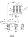
- FIG. 1 shows a pipe element 1 in which the exhaust gases of a motor vehicle engine circulate.
- This element 1 is surrounded by an annular chamber forming a sealed enclosure 2 whose wall 2 a is, for example welded to the outer wall 1 a of the pipe element.
- a conduit 3 opens at one of its ends 3 a into said annular chamber 2 and at its other end 3 b into one of the water boxes 7 of a radiator 4.
- This radiator conventionally comprises a bundle of tubes 5 lined with fins 6 and connected between the water box 7 and a second water box 10.
- This second water box is connected to the conduit 3 by a channel 8 provided with a siphon 9.
- This radiator is, for example, installed in the air flow F of the heating duct (not shown) of the passenger compartment of the vehicle.
- the device also comprises a deformable capacity 13 connected by a conduit 12 to the sealed chamber 2 surrounding the exhaust conduit.
- a spring 14 is placed in abutment between the wall 13 a of the capacity opposite the entry of the conduit 12 and an element S of the structure of the vehicle. Said spring is arranged so as to oppose the expansion of the capsule.
- the assembly thus formed closed and sealed contains a small amount of a two-phase fluid, for example water which can be added with an agent (alcohol, glycol, in particular) capable of preventing its freezing.
- a two-phase fluid for example water which can be added with an agent (alcohol, glycol, in particular) capable of preventing its freezing.
- the exhaust gases enter the pipe 1 at high temperature and tend to heat the liquid contained in the chamber 2 and bring it to a temperature sufficient to create the boil.
- This boiling temperature for a given fluid, depends on the pressure prevailing in the enclosure where it occurs. A more or less high vacuum obtained by extracting, by the valve 11, before closing the circuit, the air contained in the device, makes it possible to lower this temperature.
- the fluid vaporizes and its vapor is released towards the upper part of the chamber 2. This vapor is then brought, by the conduit 3, to the radiator 4. The vapor then bathes the tubes 5 of this exchanger to which it transmits its latent heat of vaporization, which is returned, by the fins 6, to the air which circulates through the radiator.
- the level of liquid contained in the annular chamber 2 then drops, reducing the active wetted surface for exchange with the exhaust gases circulating in the pipe 1.
- the system thus ensures, in addition to a perfect adaptation to the needs of exchanged power, total operational safety. In fact, in no case can the vapor pressure rise in the enclosure beyond the setting pressure of the compensating spring.
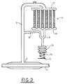
- the deformable capacity 13 is connected in the lower part of the siphon 9 formed in the condensate recovery channel 8 connected to the water box 10 of the radiator outlet 4.
- the expansion of the capacity 13 is limited by the calibration spring 14, bearing on an element S of the structure.
- the deformable capacity although no longer connecting to the low point of the device, makes it possible to accumulate a greater or lesser part of the condensed liquid, depending on the pressure prevailing in the closed enclosure, by recovering this liquid as soon as possible. the outlet of the condensing element.
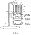
- FIG. 3 presents a simplified variant of the embodiment of FIG. 1.
- a single conduit 30 ensures both the routing of the vapors coming from the annular chamber 2 towards the radiator 4 and the return of the condensed fluid in said radiator to chamber 2.
- the conduit 30 is connected between the water box 10 leaving the radiator 4 and said vaporization chamber 2.
- the deformable capacity is integrated into the radiator outlet water box.
- said water box 40 is separated into two chambers 41, 42 by a deformable membrane 45.
- the return channel 48 of the condensed fluid is connected, on one side, to the conduit 3 for conveying the vapors, thus than previously, and on the other side in the upper part of the upper chamber 41. It is also in this chamber that the bundle of tubes 5 of the radiator opens.
- the lower chamber 42 is delimited by the partition 45 and by the lower wall 44 of the water box 40. This wall 44 is pierced with an orifice 43 for venting the aforementioned chamber.
- the membrane 45 has a profile whose convexity 45 a is oriented in the direction of the upper chamber 41, so as to reduce the internal volume of said chamber. As long as the heat inputs recovered from the exhaust gases are completely absorbed by the condenser exchanger, the condensates returning to the annular enclosure 2 circulate through the channel 48 and the conduit 3.
- the membrane 45 gradually deforms, as shown in FIGS. 4b and 4c. At the end of this deformation, the convexity 45 has said membrane is facing the bottom wall 43 of the box 40.
- the volume of the lower chamber 41 is thus increased, and forms a holding capacity whose level is located below the mouth of the exchanger outlet channel 48. In this way, the condensates produced in this exchanger accumulate in priority in the volume thus created, instead of returning to the annular enclosure.
- the upper chamber 41 can be filled with a material capable of retaining the liquid accumulated in said chamber as long as the membrane 45 remains subject to the influence of pressure.
- the embodiments described so far refer to applications of the invention intended to heat the air in the passenger compartment of a vehicle.
- the device can also be used to heat the cooling circuit of the engine of this vehicle and thus allow the temperature to rise faster.
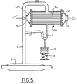
- FIG. 5 An example of such an arrangement is provided in FIG. 5. It can be seen that the circuit is basically identical to that of FIG. 1, only the condenser exchanger is different. Indeed, it is a question here of transferring the energy taken from the exhaust gases no longer to a gaseous fluid but to a liquid.
- the exchanger 54 is therefore installed on a pipe 51 of the engine cooling circuit.
- the coolant L circulates in tubes 55 installed between the water inlet box 52 and the outlet box 53.
- the vapor coming from the annular enclosure 2 is directly sent to the upper part of the exchanger, it flows between the tubes 5, and comes out at the bottom of the exchanger.
- the operation of the system is, moreover, identical to the previous cases.
- the pipe element 1 around which the annular enclosure 2 is installed may be part of the vehicle exhaust line or even part of the exhaust gas recycling duct, a certain amount of which is reintroduced into the intake duct to reduce the discharge of harmful gases into the atmosphere.
- the vaporization enclosure could no longer be installed around but inside the exhaust gas pipe.
Abstract
Description
L'invention concerne un dispositif permettant de récupérer la chaleur des gaz d'échappement des véhicules automobiles et de la restituer soit au système de chauffage de l'habitacle desdits véhicules, soit au circuit de refroidissement de leur moteur.The invention relates to a device making it possible to recover the heat from the exhaust gases of motor vehicles and to restore it either to the heating system of the passenger compartment of said vehicles, or to the cooling circuit of their engine.
L'amélioration du rendement des moteurs thermiques des véhicules automobiles tend à réduire les pertes thermiques vers le circuit de refroidissement.Improving the efficiency of thermal engines in motor vehicles tends to reduce thermal losses to the cooling circuit.
De cette réduction des pertes résulte, en particulier, une montée en température plus lente du moteur, ce qui entraîne un fonctionnement prolongé en conditions défavorables. D'autre part, cette situation prive le système de chauffage de l'habitacle, qui puise l'énergie qui lui est nécessaire sur le circuit de refroidissement, de l'apport thermique suffisant pour assurer une montée en température rapide.This reduction in losses results, in particular, in a slower rise in temperature of the engine, which leads to prolonged operation under unfavorable conditions. On the other hand, this situation deprives the heating system of the passenger compartment, which draws the energy it needs from the cooling circuit, of sufficient heat input to ensure a rapid rise in temperature.
Pour transférer de l'énergie depuis un circuit de gaz d'échappement chauds, vers un circuit de fluide à plus basse température, il est connu d'utiliser un fluide intermédiaire à changement de phase, tel que de l'eau. Ce fluide est vaporisé, par échange thermique avec les gaz d'échappement, dans un échangeur vaporiseur, et condensé, dans un échangeur condenseur, au contact du fluide à réchauffer.To transfer energy from a hot exhaust gas circuit to a fluid circuit at a lower temperature, it is known to use an intermediate phase change fluid, such as water. This fluid is vaporized, by heat exchange with the exhaust gases, in a vaporizer exchanger, and condensed, in a condenser exchanger, in contact with the fluid to be heated.
Un tel dispositif est décrit, par exemple, dans le document EP-B-189 624. Le dispositif décrit dans ce document comporte un dispositif d'absorption de la chaleur placé dans le conduit d'échappement d'un véhicule et un dispositif de restitution de la chaleur disposé dans le conduit de chauffage de l'habitacle dudit véhicule. Ces deux dispositifs sont reliés par un circuit de passage de la vapeur circulant du dispositif d'absorption au dispositif de restitution de la chaleur et un circuit de retour du liquide condensé placé entre un collecteur de ce liquide, disposé au-dessous de la partie de restitution de la chaleur, et le dispositif d'absorption de la chaleur. Ce circuit de retour comporte en outre une valve permettant de régler la quantité de fluide renvoyée vers ledit dispositif d'absorption, en fonction de la température de l'air en aval du dispositif de restitution de la chaleur. Il est ainsi possible de réguler l'apport de calories en provenance de l'échappement en fonction des besoins du système de chauffage.Such a device is described, for example, in document EP-B-189 624. The device described in this document comprises a device for absorbing heat placed in the exhaust duct of a vehicle and a device for restitution heat disposed in the heating duct of the passenger compartment of said vehicle. These two devices are connected by a circuit for the passage of the steam circulating from the absorption device to the device for the return of heat and a return circuit for the condensed liquid placed between a collector of this liquid, disposed below the part of heat recovery, and the heat absorbing device. This return circuit also includes a valve for adjusting the quantity of fluid returned to said absorption device, as a function of the temperature of the air downstream of the heat release device. It is thus possible to regulate the intake of calories from the exhaust according to the needs of the heating system.
Toutefois, on remarquera que l'énergie véhiculée par les gaz d'échappement d'un moteur thermique de véhicule automobile est très variable en fonction de la charge mécanique appliquée audit moteur. D'autre part, les besoins en récupération d'énergie n'ont pas de corrélation avec les disponibilités énergétiques sur les gaz d'échappement.However, it will be noted that the energy conveyed by the exhaust gases of a heat engine of a motor vehicle is very variable depending on the mechanical load applied to said engine. On the other hand, the energy recovery needs have no correlation with the energy availability on the exhaust gases.
Le fonctionnement du circuit de fluide biphasique, tel que décrit plus haut, suppose qu'à tout instant s'établisse un parfait équilibre entre la puissance transmise au fluide en ébullition par les gaz d'échappement et la puissance évacuée par le condenseur vers le système à réchauffer.The operation of the two-phase fluid circuit, as described above, assumes that at all times a perfect balance is established between the power transmitted to the boiling fluid by the exhaust gases and the power evacuated by the condenser to the system. to reheat.
Dans le cas contraire, le système connaîtrait des variations importantes de pression de vapeur : baisse de pression pouvant aller jusqu'à l'arrêt de fonctionnement du système dès que le niveau énergétique des gaz d'échappement ne serait plus suffisant pour maintenir la température d'ébullition, élévation de la pression pouvant conduire à la destruction du dispositif en cas de disponibilité importante d'énergie dans le circuit des gaz d'échappement dépassant les besoins en énergie de récupération.Otherwise, the system would experience significant variations in vapor pressure: pressure drop which could go as far as shutting down the system as soon as the energy level of the exhaust gases was no longer sufficient to maintain the temperature d boiling, rise in pressure which can lead to the destruction of the device in the event of significant availability of energy in the exhaust gas circuit exceeding the recovery energy requirements.
La régulation selon le document antérieur EP-B-189 624 ne permet pas de résoudre ce problème puisqu'elle n'agit qu'en fonction de la température du circuit de chauffage de l'habitacle et ne peut prendre en compte l'état du circuit des gaz d'échappement. C'est pourquoi ce document prévoit un dispositif annexe permettant de dévier le flux des gaz d'échappement de façon à éviter le dispositif d'absorption de la chaleur. Ce procédé est, d'une part complexe, et d'autre part, en agissant directement sur le flux des gaz d'échappement il risque de perturber celui-ci.The regulation according to the prior document EP-B-189 624 does not make it possible to solve this problem since it acts only as a function of the temperature of the heating circuit of the passenger compartment and cannot take into account the state of the exhaust gas circuit. This is why this document provides an additional device for diverting the flow of exhaust gases so as to avoid the heat absorption device. This process is, on the one hand complex, and on the other hand, by acting directly on the flow of exhaust gases it risks disturbing it.
La présente invention a pour but de remédier aux inconvénients précédemment décrits et de conférer ainsi au système une parfaite sécurité d'emploi et une constante adaptation de la puissance échangée aux besoins instantanés en énergie de récupération.The object of the present invention is to remedy the drawbacks described above and thus to give the system perfect job security and constant adaptation of the power exchanged to instantaneous needs for recovery energy.
A cet effet, elle a pour objet un dispositif permettant de récupérer la chaleur des gaz d'échappement d'un véhicule automobile, circulant dans un élément de canalisation, et de la restituer à un circuit de fluide à plus basse température dudit véhicule du type constitué par un circuit fermé contenant un fluide intermédiaire caloporteur et comportant un échangeur vaporiseur, en contact thermique avec les gaz d'échappement et un échangeur condenseur, en contact thermique avec le fluide à réchauffer, reliés par des conduits de circulation du fluide caloporteur en phase vapeur et/ou liquide.To this end, it relates to a device making it possible to recover the heat from the exhaust gases of a motor vehicle, circulating in a pipe element, and to restore it to a fluid circuit at lower temperature of said vehicle of the type consisting of a closed circuit containing an intermediate heat transfer fluid and comprising a vaporizer exchanger, in thermal contact with the exhaust gases and a condenser exchanger, in thermal contact with the fluid to be heated, connected by circulation pipes of the heat transfer fluid in phase vapor and / or liquid.
Une capacité déformable sous l'effet de la pression et d'une contenance suffisante pour recevoir, à l'état actif, au moins une partie du fluide caloporteur contenu dans le circuit fermé, lorsque le système est en état de déséquilibre énergétique, est montée débouchante en un point bas dudit circuit.
Selon d'autres caractéristiques et variantes de l'invention :
- L'échangeur vaporisateur est une chambre annulaire entourant un élément de canalisation dans laquelle circulent les gaz d'échappement.
- La capacité déformable est raccordée en partie basse de l'échangeur vaporisateur.
- La capacité déformable est raccordée en partie basse d'un siphon formé dans le canal de récupération des condensats en sortie de l'échangeur condenseur.
- la capacité déformable est tarée par un ressort placé entre le fond de ladite capacité et un élément de la structure du véhicule.
- L'échangeur condenseur comporte une boîte de récupération des condensats séparée en deux chambres par une membrane déformable qui présente un profil dont la convexité est orientée, en situation d'équilibre énergétique du système, en direction de la chambre supérieure. Ladite chambre joue le rôle de capacité déformable et comporte, en partie haute, le canal de retour du fluide condensé vers l'échangeur vaporiseur, et reçoit les condensats issus de l'échangeur condenseur.
- La chambre supérieure de la boîte de récupération des condensats est remplie d'une matière capable de retenir le liquide accumulé dans ladite chambre tant que la membrane reste soumise à l'influence de la pression.
- L'échangeur condenseur est un radiateur disposé dans le flux d'air de chauffage de l'habitacle du véhicule automobile.
- L'échangeur condenseur est installé sur une conduite du circuit de refroidissement du moteur du véhicule automobile.
- L'élément de canalisation dans lequel circulent les gaz d'échappement fait partie de la ligne d'échappement du véhicule automobile.
- L'élément de canalisation dans lequel circulent les gaz d'échappement fait partie du conduit permettant de réintroduire ces gaz d'échappement dans le conduit d'admission du moteur.
According to other characteristics and variants of the invention:
- The vaporizer exchanger is an annular chamber surrounding a pipe element in which the exhaust gases circulate.
- The deformable capacity is connected in the lower part of the evaporator exchanger.
- The deformable capacity is connected in the lower part of a siphon formed in the condensate recovery channel at the outlet of the condenser exchanger.
- the deformable capacity is calibrated by a spring placed between the bottom of said capacity and an element of the vehicle structure.
- The condenser exchanger includes a condensate recovery box separated into two chambers by a deformable membrane which has a profile whose convexity is oriented, in a situation of energy balance of the system, towards the upper chamber. Said chamber plays the role of deformable capacity and comprises, in the upper part, the return channel of the condensed fluid towards the evaporator exchanger, and receives the condensates from the condenser exchanger.
- The upper chamber of the condensate recovery box is filled with a material capable of retaining the liquid accumulated in said chamber as long as the membrane remains subject to the influence of pressure.
- The condenser exchanger is a radiator arranged in the air flow for heating the passenger compartment of the motor vehicle.
- The condenser exchanger is installed on a line of the cooling circuit of the motor vehicle engine.
- The pipe element in which the exhaust gases circulate is part of the exhaust line of the motor vehicle.
- The channeling element in which the exhaust gases circulate is part of the duct allowing these exhaust gases to be reintroduced into the engine intake duct.
D'autres caractéristiques et avantages de l'invention apparaîtront à la lecture de la description détaillée qui va suivre, pour la compréhension de laquelle on se reportera aux dessins annexés, dans lesquels :
- La figure 1 est une vue schématique du dispositif selon l'invention, représenté dans trois états caractéristiques de fonctionnement,
- La figure 2, 3 et 4 sont des vues semblables à la figure 1 montrant trois variantes de réalisation de l'invention,
- La figure 5 est une vue schématique du dispositif selon l'invention utilisant une variante de l'échangeur de chaleur destiné à la condensation du fluide.
- FIG. 1 is a schematic view of the device according to the invention, represented in three characteristic operating states,
- FIGS. 2, 3 and 4 are views similar to FIG. 1 showing three alternative embodiments of the invention,
- Figure 5 is a schematic view of the device according to the invention using a variant of the heat exchanger for condensing the fluid.
Sur la figure 1, est représenté un élément 1 de canalisation dans laquelle circulent les gaz d'échappement d'un moteur de véhicule automobile. Cet élément 1 est entouré par une chambre annulaire formant une enceinte étanche 2 dont la paroi 2a est, par exemple soudée sur la paroi externe 1a de l'élément de canalisation. Un conduit 3 débouche par l'une de ses extrémités 3a dans ladite chambre annulaire 2 et par son autre extrémité 3b dans l'une des boîtes à eau 7 d'un radiateur 4. Ce radiateur comporte, de façon classique, un faisceau de tubes 5 garnis d'ailettes 6 et branchés entre la boîte à eau 7 et une seconde boîte à eau 10. Cette deuxième boîte à eau est raccordée au conduit 3 par un canal 8 muni d'un siphon 9.FIG. 1 shows a
Ce radiateur est, par exemple, installé dans le flux d'air F du conduit de chauffage (non représenté) de l'habitacle du véhicule.This radiator is, for example, installed in the air flow F of the heating duct (not shown) of the passenger compartment of the vehicle.
Selon l'invention, le dispositif comporte encore une capacité déformable 13 raccordée par un conduit 12 à la chambre étanche 2 entourant le conduit d'échappement. Un ressort 14 est placé en appui entre la paroi 13a de la capacité opposée à l'entrée du conduit 12 et un élément S de la structure du véhicule. Ledit ressort est agencé de façon à s'opposer à l'expansion de la capsule.According to the invention, the device also comprises a
L'ensemble ainsi constitué clos et étanche contient une faible quantité d'un fluide biphasique, par exemple de l'eau qui peut être additionnée d'un agent (alcool, glycol, notamment) capable de prévenir sa congélation.The assembly thus formed closed and sealed contains a small amount of a two-phase fluid, for example water which can be added with an agent (alcohol, glycol, in particular) capable of preventing its freezing.
Dans un premier temps, le système étant à l'arrêt en l'absence de circulation de gaz d'échappement, le fluide contenu dans la chambre annulaire 2 est froid et la pression relative dans l'enceinte est nulle, voire même négative. Dans ces conditions (figure 1a), la capacité 13 se trouve comprimée, sous l'action du ressort 14 et la plus grande partie du liquide qu'elle est susceptible de contenir se trouve refoulée dans la chambre 2.Initially, the system being stopped in the absence of exhaust gas circulation, the fluid contained in the
Lorsque le moteur thermique est en fonctionnement, les gaz d'échappement pénètrent dans la canalisation 1 à haute température et tendent à réchauffer le liquide contenu dans la chambre 2 et à l'amener à une température suffisante pour créer l'ébullition.When the heat engine is in operation, the exhaust gases enter the
Cette température d'ébullition, pour un fluide déterminé, dépend de la pression régnant dans l'enceinte où elle se produit. Un vide plus ou moins poussé obtenu en extrayant, par le clapet 11, avant fermeture du circuit, l'air contenu dans le dispositif, permet d'abaisser cette température.This boiling temperature, for a given fluid, depends on the pressure prevailing in the enclosure where it occurs. A more or less high vacuum obtained by extracting, by the
Parvenu à sa température d'ébullition, le fluide se vaporise et sa vapeur se dégage vers la partie haute de la chambre 2. Cette vapeur est ensuite amenée, par le conduit 3, jusqu'au radiateur 4. La vapeur baigne alors les tubes 5 de cet échangeur à qui elle transmet sa chaleur latente de vaporisation, laquelle est restituée, par les ailettes 6, à l'air qui circule à travers le radiateur.Having reached its boiling point, the fluid vaporizes and its vapor is released towards the upper part of the
Sous l'effet de cet échange de chaleur, la vapeur se condense le long de la paroi interne des tubes 5 et le liquide provenant de cette condensation finit par s'écouler le long desdits tubes puis, de là, dans la boîte à eau 10 avant de retourner, par simple gravité, vers la chambre annulaire 2 en circulant dans le canal 8 et, à contre-courant par rapport à la vapeur, dans le conduit de liaison 3.Under the effect of this heat exchange, the vapor condenses along the internal wall of the
Ce mode de fonctionnement se poursuit tant que la pression dans l'enceinte reste modérée et inférieure à la pression de tarage du ressort 14. Dès que cette pression dépasse la limite de tarage dudit ressort, son action sur la face inférieure de la capacité 13 tend à déformer cette dernière et à accroître son volume (figure 2b). Dans ce cas, une certaine quantité de liquide se trouve prélevée dans la chambre 2 de vaporisation, pour pénétrer dans le la capacité déformable, par le conduit 12.This operating mode continues as long as the pressure in the enclosure remains moderate and below the
Le niveau de liquide contenu dans la chambre annulaire 2 s'abaisse alors, réduisant la surface mouillée active d'échange avec les gaz d'échappement circulant dans la tubulure 1.The level of liquid contained in the
De cette diminution de surface active résulte une réduction de l'énergie prélevée sur les gaz. A son tour, cette réduction de l'énergie récupérée tend à faire baisser la pression dans l'enceinte et ceci jusqu'au rétablissement de l'équilibre entre la puissance absorbée sur les gaz d'échappement et la puissance cédée au circuit d'utilisation.This reduction in active surface results in a reduction in the energy taken from the gases. In turn, this reduction in the energy recovered tends to lower the pressure in the enclosure and this until the equilibrium between the power absorbed on the exhaust gases and the power transferred to the operating circuit is restored. .
Si l'accroissement du déséquilibre entre ces deux puissances devait se poursuivre, la pression dans l'enceinte tendrait encore à s'élever et entraînerait une déformation de plus en plus importante de la capacité 13 et la compression du ressort de tarage 14 jusqu'à ce que la totalité du fluide contenu dans le circuit se retrouve dans la capacité déformable.If the increase in the imbalance between these two powers were to continue, the pressure in the enclosure would still tend to rise and would cause an increasingly significant deformation of the
En cette condition extrême, par manque de fluide à vaporiser, le système s'arrêterait de fonctionner jusqu'à ce que, la pression dans l'ensemble s'étant abaissée, la capacité 13 restitue à la chambre de vaporisation une quantité de fluide suffisante pour permettre au cycle normal de reprendre.In this extreme condition, for lack of fluid to vaporize, the system would stop operating until, the pressure in the assembly having dropped, the
Dans ces conditions, on peut voir que le système tend de manière automatique à fonctionner à pression de vapeur constante, quelle que soit l'énergie disponible sur les gaz d'échappement et quelle que soit la dissipation vers le circuit récupérateur.Under these conditions, it can be seen that the system automatically tends to operate at constant vapor pressure, whatever the energy available on the exhaust gases and whatever the dissipation towards the recovery circuit.
Le système assure ainsi, en plus d'une parfaite adaptation aux besoins de puissance échangée, une totale sécurité de fonctionnement. En effet, en aucun cas la pression de vapeur ne peut s'élever dans l'enceinte au- delà de la pression de tarage du ressort compensateur.The system thus ensures, in addition to a perfect adaptation to the needs of exchanged power, total operational safety. In fact, in no case can the vapor pressure rise in the enclosure beyond the setting pressure of the compensating spring.
Dans le mode de réalisation de l'invention représenté sur la figure 2, la capacité déformable 13 est raccordée en partie basse du siphon 9 formé dans le canal 8 de récupération des condensats branché sur la boîte à eau 10 de sortie du radiateur 4. Comme précédemment l'expansion de la capacité 13 est limitée par le ressort de tarage 14, en appui sur un élément S de la structure.In the embodiment of the invention shown in Figure 2, the
Dans cette configuration la capacité déformable, bien que ne se raccordant plus au point bas du dispositif, permet d'accumuler une partie plus ou moins grande du liquide condensé, en fonction de la pression régnant dans l'enceinte fermée, en récupérant ce liquide dès la sortie de l'élément de condensation.In this configuration, the deformable capacity, although no longer connecting to the low point of the device, makes it possible to accumulate a greater or lesser part of the condensed liquid, depending on the pressure prevailing in the closed enclosure, by recovering this liquid as soon as possible. the outlet of the condensing element.
La figure 3 présente une variante simplifiée du mode de réalisation de la figure 1. Dans cette configuration, un seul conduit 30 assure à la fois l'acheminement des vapeurs issues de la chambre annulaire 2 vers le radiateur 4 et le retour du fluide condensé dans ledit radiateur vers la chambre 2. Dans ce cas, le conduit 30 est branché entre la boîte à eau 10 de sortie du radiateur 4 et ladite chambre de vaporisation 2.FIG. 3 presents a simplified variant of the embodiment of FIG. 1. In this configuration, a
Dans le mode de réalisation représenté figure 4, la capacité déformable est intégrée à la boîte à eau de sortie du radiateur. Pour ce faire, ladite boîte à eau 40 est séparée en deux chambres 41, 42 par une membrane déformable 45. Le canal 48 de retour du fluide condensé est branché, d'un côté, sur le conduit 3 d'acheminement des vapeurs, ainsi que précédemment, et de l'autre côté en partie haute de la chambre supérieure 41. C'est également dans cette chambre que débouche le faisceau des tubes 5 du radiateur. La chambre inférieure 42 est délimitée par la cloison 45 et par la paroi inférieure 44 de la boîte à eau 40. Cette paroi 44 est percée d'un orifice 43 de mise à l'air libre de la chambre précitée.In the embodiment shown in FIG. 4, the deformable capacity is integrated into the radiator outlet water box. To do this, said
Initialement, la membrane 45 présente un profil dont la convexité 45a est orientée en direction de la chambre supérieure 41, de façon à réduire le volume interne de ladite chambre. Tant que les apports calorifiques récupérés sur les gaz d'échappement se trouvent entièrement absorbés par l'échangeur condenseur, les condensats retournant vers l'enceinte annulaire 2 circulent à travers le canal 48 et le conduit 3.Initially, the
Lorsque la disponibilité d'énergie dans le circuit des gaz d'échappement devient supérieure à l'énergie dissipée par le radiateur 4, la température du fluide caloporteur tend à s'élever entraînant une élévation de pression dans le circuit et, notamment, dans la chambre 41. Cette pression se trouve transmise directement à la membrane 45.When the availability of energy in the exhaust gas circuit becomes greater than the energy dissipated by the
Sous l'influence de cette augmentation de pression, la membrane 45 se déforme progressivement, comme représenté aux figures 4b et 4c. A la fin de cette déformation, la convexité 45a de ladite membrane est tournée vers la paroi inférieure 43 de la boîte 40. Le volume de la chambre inférieure 41 est ainsi augmenté et forme une capacité de rétention dont le niveau est situé en dessous de l'embouchure du canal 48 de sortie de l'échangeur. De la sorte, les condensats produits dans cet échangeur viennent en priorité s'accumuler dans le volume ainsi créé, au lieu de retourner vers l'enceinte annulaire.Under the influence of this increase in pressure, the
Lorsque le système sera de nouveau en équilibre énergétique, l'abaissement de la température et donc de la pression dans le circuit réduira les contraintes exercées sur la membrane 45. Celle-ci reprendra progressivement sa forme initiale, refoulant le liquide vers le haut de la chambre 41, en direction du canal de sortie 48.When the system is again in energy balance, lowering the temperature and therefore the pressure in the circuit will reduce the stresses exerted on the
Dans ce mode de réalisation et pour tenir compte des forces induites par le déplacement du véhicule, la chambre supérieure 41 peut être remplie d'une matière capable de retenir le liquide accumulé dans ladite chambre tant que la membrane 45 reste soumise à l'influence de la pression.In this embodiment and to take account of the forces induced by the movement of the vehicle, the
Les exemples de réalisation décrits jusqu'ici se réfère à des applications de l'invention destinées à réchauffer l'air de l'habitacle d'un véhicule. Comme on l'a déjà dit, le dispositif est également utilisable pour réchauffer le circuit de refroidissement du moteur de ce véhicule et permettre ainsi une montée en température plus rapide de ce dernier.The embodiments described so far refer to applications of the invention intended to heat the air in the passenger compartment of a vehicle. As has already been said, the device can also be used to heat the cooling circuit of the engine of this vehicle and thus allow the temperature to rise faster.
Un exemple d'un tel agencement est fourni figure 5. On voit que le circuit est fondamentalement identique à celui de la figure 1, seul l'échangeur condenseur est différent. En effet, il s'agit ici de céder l'énergie prélevée sur les gaz d'échappement non plus à un fluide gazeux mais à un liquide. L'échangeur 54 est donc installé sur une conduite 51 du circuit de refroidissement du moteur. Le liquide de refroidissement L circule dans des tubes 55 installés entre la boîte d'entrée d'eau 52 et la boîte de sortie 53. La vapeur en provenance de l'enceinte annulaire 2 est directement envoyée en partie haute de l'échangeur, elle circule entre les tubes 5, et ressort en partie basse de l'échangeur. Le fonctionnement du système est, par ailleurs, identique aux cas précédents.An example of such an arrangement is provided in FIG. 5. It can be seen that the circuit is basically identical to that of FIG. 1, only the condenser exchanger is different. Indeed, it is a question here of transferring the energy taken from the exhaust gases no longer to a gaseous fluid but to a liquid. The
Bien entendu ce type d'échangeur peut être utilisé avec n'importe laquelle des variantes précédentes.Of course, this type of exchanger can be used with any of the previous variants.
L'élément de canalisation 1 autour duquel est installé l'enceinte annulaire 2 peut-être une partie de la ligne d'échappement du véhicule ou bien encore une partie du conduit de recyclage des gaz d'échappement dont une certaine quantité est réintroduite dans le conduit d'admission en vue de réduire le rejet des gaz nocifs dans l'atmosphère.The
Cette deuxième solution est doublement avantageuse. En effet, le système de recyclage des gaz est déjà pourvu de moyens permettant de l'interrompre lorsque le moteur est en pleine charge, ce qui diminue les risques de fonctionnement du dispositif selon des conditions extrêmes. D'un autre côté, l'installation du dispositif de récupération de l'énergie, en abaissant la température des gaz d'échappement recyclés permet d'augmenter leur quantité et, par conséquent, de diminuer la pollution du moteur.This second solution is doubly advantageous. In fact, the gas recycling system is already equipped with means making it possible to interrupt it when the engine is fully loaded, which reduces the risks of the device operating under extreme conditions. On the other hand, the installation of the energy recovery device, by lowering the temperature of the recycled exhaust gases makes it possible to increase their quantity and, consequently, to reduce pollution of the engine.
D'autres variantes sont encore possibles sans sortir du cadre de la présente invention. C'est ainsi, par exemple, que l'enceinte de vaporisation pourrait être installée non plus autour mais à l'intérieur de la conduite des gaz d'échappement.Other variants are still possible without departing from the scope of the present invention. Thus, for example, the vaporization enclosure could no longer be installed around but inside the exhaust gas pipe.
Claims (11)
caractérisé en ce qu'une capacité (13, 41) déformable sous l'effet de la pression et d'une contenance suffisante pour recevoir, à l'état actif, au moins une partie du fluide caloporteur contenu dans le circuit fermé, lorsque le système est en état de déséquilibre énergétique, est montée débouchante en un point bas dudit circuit.Device making it possible to recover the heat from the exhaust gases of a motor vehicle, circulating in a pipe element (1), and to restore it to a fluid circuit at lower temperature of said vehicle constituted by a closed circuit containing a fluid heat transfer intermediate and comprising a vaporizer exchanger (2), in thermal contact with the exhaust gases and a condenser exchanger (4,54), in thermal contact with the fluid to be heated, connected by conduits (3,30), ( 8.48) circulation of the heat transfer fluid in vapor and / or liquid phase,
characterized in that a capacity (13, 41) deformable under the effect of the pressure and of a sufficient capacity to receive, in the active state, at least part of the heat transfer fluid contained in the closed circuit, when the system is in a state of energy imbalance, is mounted emerging at a low point of said circuit.
caractérisé en ce que l'échangeur vaporisateur (2) est une chambre annulaire entourant un élément de canalisation (1) dans laquelle circulent les gaz d'échappement.Device according to claim 1,
characterized in that the vaporizing exchanger (2) is an annular chamber surrounding a pipe element (1) in which the exhaust gases circulate.
caractérisé en ce que la capacité déformable (13) est raccordée en partie basse de l'échangeur vaporisateur (2).Device according to claim 1 or 2,
characterized in that the deformable capacity (13) is connected in the lower part of the evaporator exchanger (2).
caractérisé en ce que la capacité déformable (13) est raccordée en partie basse d'un siphon (9) formé dans le canal (8) de récupération des condensats en sortie de l'échangeur condenseur (4).Device according to claim 1 or 2,
characterized in that the deformable capacity (13) is connected in the lower part of a siphon (9) formed in the channel (8) for recovering condensates at the outlet of the condenser exchanger (4).
caractérisé en ce que la capacité déformable (13) est tarée par un ressort (14) placé entre le fond (13a) de ladite capacité et un élément (S) de la structure du véhicule.Device according to one of the preceding claims,
characterized in that the deformable capacity (13) is calibrated by a spring (14) placed between the bottom (13 a ) of said capacity and an element ( S ) of the vehicle structure.
caractérisé en ce que l'échangeur condenseur (4) comporte une boîte de récupération des condensats (40) séparée en deux chambres (41),(42) par une membrane déformable (45) qui présente un profil dont la convexité (45a) est orientée, en situation d'équilibre énergétique du système, en direction de la chambre supérieure (41) laquelle joue le rôle de capacité déformable et comporte, en partie haute, le canal (48,3) de retour du fluide condensé vers l'échangeur vaporiseur (2), et reçoit les condensats issus de l'échangeur condenseur (4).Device according to claim 1 or 2,
characterized in that the condenser exchanger (4) comprises a condensate recovery box (40) separated into two chambers (41), (42) by a deformable membrane (45) which has a profile whose convexity (45 a ) is oriented, in a situation of energy balance of the system, in the direction of the upper chamber (41) which plays the role of deformable capacity and comprises, in the upper part, the channel (48.3) for the return of the condensed fluid evaporator exchanger (2), and receives the condensates from the condenser exchanger (4).
caractérisé en ce que la chambre supérieure (41) de la boîte de récupération des condensats (40) est remplie d'une matière capable de retenir le liquide accumulé dans ladite chambre tant que la membrane (45) reste soumise à l'influence de la pression.Device according to claim 6
characterized in that the upper chamber (41) of the condensate recovery box (40) is filled with a material capable of retaining the liquid accumulated in said chamber as long as the membrane (45) remains subject to the influence of the pressure.
caractérisé en ce que l'échangeur condenseur (4) est un radiateur disposé dans le flux d'air de chauffage de l'habitacle du véhicule automobile.Device according to one of the preceding claims,
characterized in that the condenser exchanger (4) is a radiator arranged in the air flow for heating the passenger compartment of the motor vehicle.
caractérisé en ce que l'échangeur condenseur (4) est installé sur une conduite (51) du circuit de refroidissement du moteur du véhicule automobile.Device according to one of the preceding claims,
characterized in that the condenser exchanger (4) is installed on a line (51) of the motor vehicle engine cooling circuit.
caractérisé en ce que l'élément de canalisation (1) dans lequel circulent les gaz d'échappement fait partie de la ligne d'échappement du véhicule automobile.Device according to one of the preceding claims,
characterized in that the pipe element (1) in which the exhaust gases circulate is part of the exhaust line of the motor vehicle.
caractérisé en ce que l'élément de canalisation (1) dans lequel circulent les gaz d'échappement fait partie du conduit permettant de réintroduire ces gaz d'échappement dans le conduit d'admission du moteur.Device according to one of claims 2 to 9,
characterized in that the channeling element (1) in which the exhaust gases circulate is part of the duct making it possible to reintroduce these exhaust gases into the intake duct of the engine.
Priority Applications (2)
| Application Number | Priority Date | Filing Date | Title |
|---|---|---|---|
| DE1995624414 DE69524414T2 (en) | 1995-10-06 | 1995-10-06 | Heat recovery system from vehicle exhaust gases |
| EP19950402232 EP0767081B1 (en) | 1995-10-06 | 1995-10-06 | Device for the recovery of heat from the exhaust gases of a vehicle |
Applications Claiming Priority (1)
| Application Number | Priority Date | Filing Date | Title |
|---|---|---|---|
| EP19950402232 EP0767081B1 (en) | 1995-10-06 | 1995-10-06 | Device for the recovery of heat from the exhaust gases of a vehicle |
Publications (2)
| Publication Number | Publication Date |
|---|---|
| EP0767081A1 true EP0767081A1 (en) | 1997-04-09 |
| EP0767081B1 EP0767081B1 (en) | 2001-12-05 |
Family
ID=8221533
Family Applications (1)
| Application Number | Title | Priority Date | Filing Date |
|---|---|---|---|
| EP19950402232 Expired - Lifetime EP0767081B1 (en) | 1995-10-06 | 1995-10-06 | Device for the recovery of heat from the exhaust gases of a vehicle |
Country Status (2)
| Country | Link |
|---|---|
| EP (1) | EP0767081B1 (en) |
| DE (1) | DE69524414T2 (en) |
Cited By (2)
| Publication number | Priority date | Publication date | Assignee | Title |
|---|---|---|---|---|
| US10428713B2 (en) | 2017-09-07 | 2019-10-01 | Denso International America, Inc. | Systems and methods for exhaust heat recovery and heat storage |
| JP2020044896A (en) * | 2018-09-17 | 2020-03-26 | マツダ株式会社 | Air conditioner for vehicle |
Families Citing this family (1)
| Publication number | Priority date | Publication date | Assignee | Title |
|---|---|---|---|---|
| DE102017105612A1 (en) | 2017-03-16 | 2018-09-20 | Volkswagen Aktiengesellschaft | Drive system and motor vehicle |
Citations (6)
| Publication number | Priority date | Publication date | Assignee | Title |
|---|---|---|---|---|
| FR687423A (en) * | 1928-12-31 | 1930-08-08 | Heating device for vehicles powered by combustion engines | |
| US1986893A (en) * | 1929-11-04 | 1935-01-08 | Harold S Hasbrouck | Steam heater for motor vehicles |
| DE2551911A1 (en) * | 1975-11-19 | 1977-06-02 | Daimler Benz Ag | HEATING DEVICE |
| EP0189624A2 (en) * | 1985-01-30 | 1986-08-06 | Sanoh Kogyo Kabushiki Kaisha | System for heating interior spaces of engine-driven vehicles |
| EP0496942A1 (en) * | 1991-01-31 | 1992-08-05 | Firma Carl Freudenberg | Vapour-cooled internal combustion engine |
| FR2718491A1 (en) * | 1994-04-08 | 1995-10-13 | Robin Roger Claude | Unit to recover heat from heat engine exhaust |
-
1995
- 1995-10-06 DE DE1995624414 patent/DE69524414T2/en not_active Expired - Fee Related
- 1995-10-06 EP EP19950402232 patent/EP0767081B1/en not_active Expired - Lifetime
Patent Citations (7)
| Publication number | Priority date | Publication date | Assignee | Title |
|---|---|---|---|---|
| FR687423A (en) * | 1928-12-31 | 1930-08-08 | Heating device for vehicles powered by combustion engines | |
| US1986893A (en) * | 1929-11-04 | 1935-01-08 | Harold S Hasbrouck | Steam heater for motor vehicles |
| DE2551911A1 (en) * | 1975-11-19 | 1977-06-02 | Daimler Benz Ag | HEATING DEVICE |
| EP0189624A2 (en) * | 1985-01-30 | 1986-08-06 | Sanoh Kogyo Kabushiki Kaisha | System for heating interior spaces of engine-driven vehicles |
| EP0189624B1 (en) | 1985-01-30 | 1989-06-07 | Sanoh Kogyo Kabushiki Kaisha | System for heating interior spaces of engine-driven vehicles |
| EP0496942A1 (en) * | 1991-01-31 | 1992-08-05 | Firma Carl Freudenberg | Vapour-cooled internal combustion engine |
| FR2718491A1 (en) * | 1994-04-08 | 1995-10-13 | Robin Roger Claude | Unit to recover heat from heat engine exhaust |
Cited By (2)
| Publication number | Priority date | Publication date | Assignee | Title |
|---|---|---|---|---|
| US10428713B2 (en) | 2017-09-07 | 2019-10-01 | Denso International America, Inc. | Systems and methods for exhaust heat recovery and heat storage |
| JP2020044896A (en) * | 2018-09-17 | 2020-03-26 | マツダ株式会社 | Air conditioner for vehicle |
Also Published As
| Publication number | Publication date |
|---|---|
| EP0767081B1 (en) | 2001-12-05 |
| DE69524414T2 (en) | 2002-08-08 |
| DE69524414D1 (en) | 2002-01-17 |
Similar Documents
| Publication | Publication Date | Title |
|---|---|---|
| EP0832411B1 (en) | Capillary pumped heat transfer loop | |
| EP2032440B1 (en) | Capillary pumped diphasic fluid loop passive thermal control device with heat capacity | |
| FR2899960A1 (en) | EXHAUST HEAT RECOVERY DEVICE | |
| FR2699365A1 (en) | System for dissipating the heat energy released by an electronic component. | |
| FR3094070A1 (en) | A device and method for storing and supplying fluid fuel. | |
| WO2017103449A1 (en) | Battery pack cooled by a constant-pressure phase-change material | |
| EP2108910B1 (en) | Internal heat exchanger comprising a means for thermal storage and loop incorporating such heat exchanger | |
| FR2723187A1 (en) | ENERGY TRANSFER SYSTEM BETWEEN A HOT SOURCE AND A COLD SOURCE | |
| EP0550748B1 (en) | Solid/gas reaction cooling plant having a reactor equipped with cooling means | |
| EP0767081B1 (en) | Device for the recovery of heat from the exhaust gases of a vehicle | |
| WO1999018387A1 (en) | Method and installation for filling a tank under pressure | |
| FR2915520A1 (en) | Engine e.g. jet engine, assembly arrangement for aircraft, has heat pipe arranging evaporation end mounted on rectifier stage, and condensation end mounted on nacelle wall that radially determines annular fresh air flow channel | |
| FR2718491A1 (en) | Unit to recover heat from heat engine exhaust | |
| WO2011045507A1 (en) | Improved air-conditioning device | |
| JP2007024424A (en) | Exhaust heat recovery device and refrigerant filling method of exhaust heat recovery device | |
| CA1227978A (en) | Phase change solar heating system | |
| FR2951256A1 (en) | AIR CONDITIONING DEVICE COMPRISING A REGULATED LEVEL TANK | |
| FR2682175A1 (en) | Protection against freezing in liquefied gas vaporiser - utilises chambers with removable deformable walls at inlet and outlet of heat transfer fluid and deformable sealed tubes in exchanger tubes | |
| BE882280A (en) | HEAT TRANSFER DEVICE AND METHOD | |
| FR2510183A1 (en) | Engine waste energy recovery circuit - uses exhaust heat to vaporise fluid supplying supercharger turbine | |
| EP1451463B1 (en) | Regulator thermostat support of heat engine with external hot water circuit | |
| EP2981781A1 (en) | Heat pipe comprising a cut-off gas plug | |
| WO2013000547A1 (en) | Coolant circuit comprising two means for storing coolant | |
| FR2721655A1 (en) | Evaporative cooling system for IC engine | |
| FR2701549A1 (en) | Rotating air-conditioner |
Legal Events
| Date | Code | Title | Description |
|---|---|---|---|
| PUAI | Public reference made under article 153(3) epc to a published international application that has entered the european phase |
Free format text: ORIGINAL CODE: 0009012 |
|
| AK | Designated contracting states |
Kind code of ref document: A1 Designated state(s): DE FR GB IT |
|
| 17P | Request for examination filed |
Effective date: 19970801 |
|
| 17Q | First examination report despatched |
Effective date: 19990223 |
|
| GRAG | Despatch of communication of intention to grant |
Free format text: ORIGINAL CODE: EPIDOS AGRA |
|
| GRAG | Despatch of communication of intention to grant |
Free format text: ORIGINAL CODE: EPIDOS AGRA |
|
| GRAH | Despatch of communication of intention to grant a patent |
Free format text: ORIGINAL CODE: EPIDOS IGRA |
|
| GRAH | Despatch of communication of intention to grant a patent |
Free format text: ORIGINAL CODE: EPIDOS IGRA |
|
| GRAA | (expected) grant |
Free format text: ORIGINAL CODE: 0009210 |
|
| AK | Designated contracting states |
Kind code of ref document: B1 Designated state(s): DE FR GB IT |
|
| REG | Reference to a national code |
Ref country code: GB Ref legal event code: IF02 |
|
| GBT | Gb: translation of ep patent filed (gb section 77(6)(a)/1977) |
Effective date: 20011206 |
|
| REF | Corresponds to: |
Ref document number: 69524414 Country of ref document: DE Date of ref document: 20020117 |
|
| PLBE | No opposition filed within time limit |
Free format text: ORIGINAL CODE: 0009261 |
|
| STAA | Information on the status of an ep patent application or granted ep patent |
Free format text: STATUS: NO OPPOSITION FILED WITHIN TIME LIMIT |
|
| 26N | No opposition filed | ||
| PGFP | Annual fee paid to national office [announced via postgrant information from national office to epo] |
Ref country code: FR Payment date: 20050831 Year of fee payment: 11 |
|
| PGFP | Annual fee paid to national office [announced via postgrant information from national office to epo] |
Ref country code: GB Payment date: 20060926 Year of fee payment: 12 |
|
| PGFP | Annual fee paid to national office [announced via postgrant information from national office to epo] |
Ref country code: DE Payment date: 20060928 Year of fee payment: 12 |
|
| PGFP | Annual fee paid to national office [announced via postgrant information from national office to epo] |
Ref country code: IT Payment date: 20061031 Year of fee payment: 12 |
|
| GBPC | Gb: european patent ceased through non-payment of renewal fee |
Effective date: 20071006 |
|
| PG25 | Lapsed in a contracting state [announced via postgrant information from national office to epo] |
Ref country code: DE Free format text: LAPSE BECAUSE OF NON-PAYMENT OF DUE FEES Effective date: 20080501 |
|
| REG | Reference to a national code |
Ref country code: FR Ref legal event code: ST Effective date: 20080630 |
|
| PG25 | Lapsed in a contracting state [announced via postgrant information from national office to epo] |
Ref country code: GB Free format text: LAPSE BECAUSE OF NON-PAYMENT OF DUE FEES Effective date: 20071006 |
|
| PG25 | Lapsed in a contracting state [announced via postgrant information from national office to epo] |
Ref country code: FR Free format text: LAPSE BECAUSE OF NON-PAYMENT OF DUE FEES Effective date: 20071031 |
|
| PG25 | Lapsed in a contracting state [announced via postgrant information from national office to epo] |
Ref country code: FR Free format text: LAPSE BECAUSE OF NON-PAYMENT OF DUE FEES Effective date: 20061031 |
|
| PG25 | Lapsed in a contracting state [announced via postgrant information from national office to epo] |
Ref country code: IT Free format text: LAPSE BECAUSE OF NON-PAYMENT OF DUE FEES Effective date: 20071006 |