EP0766344A2 - Brückenverbinder - Google Patents
Brückenverbinder Download PDFInfo
- Publication number
- EP0766344A2 EP0766344A2 EP96306610A EP96306610A EP0766344A2 EP 0766344 A2 EP0766344 A2 EP 0766344A2 EP 96306610 A EP96306610 A EP 96306610A EP 96306610 A EP96306610 A EP 96306610A EP 0766344 A2 EP0766344 A2 EP 0766344A2
- Authority
- EP
- European Patent Office
- Prior art keywords
- conductive
- core
- jumper connector
- accessible
- circuit board
- Prior art date
- Legal status (The legal status is an assumption and is not a legal conclusion. Google has not performed a legal analysis and makes no representation as to the accuracy of the status listed.)
- Granted
Links
- 229920001971 elastomer Polymers 0.000 claims abstract description 25
- 239000000806 elastomer Substances 0.000 claims abstract description 25
- PXHVJJICTQNCMI-UHFFFAOYSA-N Nickel Chemical compound [Ni] PXHVJJICTQNCMI-UHFFFAOYSA-N 0.000 claims description 10
- 239000011231 conductive filler Substances 0.000 claims description 9
- 239000006229 carbon black Substances 0.000 claims description 8
- 239000000945 filler Substances 0.000 claims description 7
- RYGMFSIKBFXOCR-UHFFFAOYSA-N Copper Chemical compound [Cu] RYGMFSIKBFXOCR-UHFFFAOYSA-N 0.000 claims description 5
- BQCADISMDOOEFD-UHFFFAOYSA-N Silver Chemical compound [Ag] BQCADISMDOOEFD-UHFFFAOYSA-N 0.000 claims description 5
- 229910052802 copper Inorganic materials 0.000 claims description 5
- 239000010949 copper Substances 0.000 claims description 5
- 239000002184 metal Substances 0.000 claims description 5
- 229910052751 metal Inorganic materials 0.000 claims description 5
- 229910052759 nickel Inorganic materials 0.000 claims description 5
- 239000000843 powder Substances 0.000 claims description 5
- 229910052709 silver Inorganic materials 0.000 claims description 5
- 239000004332 silver Substances 0.000 claims description 5
- 239000011159 matrix material Substances 0.000 claims description 3
- 230000002093 peripheral effect Effects 0.000 claims description 3
- 239000011162 core material Substances 0.000 description 34
- 229920002379 silicone rubber Polymers 0.000 description 4
- 239000004945 silicone rubber Substances 0.000 description 4
- 239000004677 Nylon Substances 0.000 description 2
- 238000003491 array Methods 0.000 description 2
- 238000004519 manufacturing process Methods 0.000 description 2
- 239000000463 material Substances 0.000 description 2
- 229920001778 nylon Polymers 0.000 description 2
- 239000004033 plastic Substances 0.000 description 2
- 229920003023 plastic Polymers 0.000 description 2
- 239000002131 composite material Substances 0.000 description 1
- 239000013013 elastic material Substances 0.000 description 1
Images


Classifications
-
- H—ELECTRICITY
- H01—ELECTRIC ELEMENTS
- H01R—ELECTRICALLY-CONDUCTIVE CONNECTIONS; STRUCTURAL ASSOCIATIONS OF A PLURALITY OF MUTUALLY-INSULATED ELECTRICAL CONNECTING ELEMENTS; COUPLING DEVICES; CURRENT COLLECTORS
- H01R31/00—Coupling parts supported only by co-operation with counterpart
- H01R31/08—Short-circuiting members for bridging contacts in a counterpart
-
- H—ELECTRICITY
- H05—ELECTRIC TECHNIQUES NOT OTHERWISE PROVIDED FOR
- H05K—PRINTED CIRCUITS; CASINGS OR CONSTRUCTIONAL DETAILS OF ELECTRIC APPARATUS; MANUFACTURE OF ASSEMBLAGES OF ELECTRICAL COMPONENTS
- H05K3/00—Apparatus or processes for manufacturing printed circuits
- H05K3/22—Secondary treatment of printed circuits
- H05K3/222—Completing of printed circuits by adding non-printed jumper connections
-
- H—ELECTRICITY
- H01—ELECTRIC ELEMENTS
- H01R—ELECTRICALLY-CONDUCTIVE CONNECTIONS; STRUCTURAL ASSOCIATIONS OF A PLURALITY OF MUTUALLY-INSULATED ELECTRICAL CONNECTING ELEMENTS; COUPLING DEVICES; CURRENT COLLECTORS
- H01R12/00—Structural associations of a plurality of mutually-insulated electrical connecting elements, specially adapted for printed circuits, e.g. printed circuit boards [PCB], flat or ribbon cables, or like generally planar structures, e.g. terminal strips, terminal blocks; Coupling devices specially adapted for printed circuits, flat or ribbon cables, or like generally planar structures; Terminals specially adapted for contact with, or insertion into, printed circuits, flat or ribbon cables, or like generally planar structures
- H01R12/70—Coupling devices
- H01R12/71—Coupling devices for rigid printing circuits or like structures
- H01R12/712—Coupling devices for rigid printing circuits or like structures co-operating with the surface of the printed circuit or with a coupling device exclusively provided on the surface of the printed circuit
- H01R12/716—Coupling device provided on the PCB
- H01R12/718—Contact members provided on the PCB without an insulating housing
Definitions
- the invention relates to a jumper connector electrically to connect to one another two contacts or terminals on a printed circuit board.
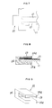
- FIG. 10 of the accompanying drawings shows a typical example of prior art jumper connectors 4 in use with a pin header 2.
- the pin header mounted on a printed circuit board 1 has an array of contact pins or posts 3.
- Each jumper connector 4 electrically connects any one of those pins to a neighbouring one of the pins and comprises two sockets 6 fittable on those pins 3 and united together by a conductive piece 7 to form a socket contact 5 secured in an insulating housing 8.
- a conductive piece 7 to form a socket contact 5 secured in an insulating housing 8.
- the prior art jumper connectors 4 are however somewhat disadvantageous in that their socket contacts 5 are complicated in structure and expensive to manufacture. They also occupy a considerably large space on a circuit board, thereby failing to match a high density arrangement of contact pins or posts.
- a jumper connector for making an electric connection between contact pins or posts protruding from a printed circuit board, or between patterned conductive portions formed thereon, the jumper connector comprising:
- Such a jumper connector can be simple in structure, inexpensive and suitable for use with high density arrays of contact pins while allowing the resistance of its conductive core to be selected as desired.
- the conductive elastomer forming the accessible core contains an amount of a conductive filler dispersed in an elastomeric matrix.
- the amount is selected to meet an electric resistance of a level required for the core.
- the filler is preferably carbon black or a powder of conductive and stable metal such as copper, nickel and silver.
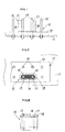
- a jumper connector 15 is designed for use with a pin header 12.
- the pin header is mounted on a printed circuit board 11, and has a base housing 13 penetrated by a plurality of upright contact pins or posts 14.
- the jumper connector 15 comprises an accessible core 16 that is a short column elliptic in cross section and made of a conductive elastomer.
- a pair of apertures 17 are formed through the core 16 to open at opposite ends thereof. Two of the contact pins or posts 14 will be fitted in the apertures 17 for making a "jumper connection”.
- An insulating mantle 18 made of a nonconductive elastomer covers a whole outer periphery of the accessible core 16.
- materials forming the core 16 and the mantle 18 may for example be extruded simultaneously through a common duplex. A composite elongate rod thus produced will subsequently be severed into lengths. In each length, i.e., the jumper connector, the core 16 is integrally bonded to the mantle 18.
- the conductive elastomer forming the core 16 is preferably a silicone rubber having an amount of carbon black dispersed therein. Carbon black as the conductive filler may be replaced with a powder of any conductive metal such as copper, nickel or silver. The amount of such a filler can be voluntarily selected to meet a required resistance of the accessible core 16.
- the insulating mantle 18 is preferably made of a certain nonconductive elastomer, as noted above.
- This elastomer may be the same or a different silicone rubber that is free of conductive filler but miscible with the core material. It is also possible to use as the mantle a hard cover formed of Nylon (a registered trademark) or a similar insulating plastics.
- the jumper connector 15 will be used in a manner as seen in Figures 1 and 2.
- the apertures 17 in the accessible core 16 fit on two neighbouring ones of the pins or posts 14. Due to elasticity of the core 16, those pins electrically connected therethrough will be held in tight contact with inner peripheral surfaces of the respective apertures 17.
- a "jumper connection" thus made between the pins 14 will have a predetermined electric resistance. This resistance inherent in the core 16 is freely chosen by varying the amount of conductive filler such as carbon black dispersed in the elastomer, as noted above.
- a jumper connector 22 in a second embodiment shown in Figures 4 to 6 is designed for use with a printed circuit board 11 whose patterned conductive portions 21 are to be jumper connected.
- This connector 22 comprises an accessible core 23 made of a conductive elastomer but is U-shaped in cross section in this case. Therefore, this U-shaped core 23 can grip with its elastic force the circuit board 11.
- an insulating mantle 24 integral with and covering an outer surface of said conductive core 23 is of a U shape.
- the conductive elastomer forming the accessible core 23 in this case is also preferably composed of a silicone rubber and a conductive filler dispersed therein.
- the filler is carbon black or a metal powder such as copper, nickel or silver.
- the amount of filler may be selected to give the core a predetermined resistance.
- the insulating mantle 24 is preferably made of a nonconductive elastomer free of conductive filler but having affinity to the core material. It is also possible to use as the mantle a hard cover formed of Nylon or like insulating plastics.
- the printed pattern may comprise, in addition to the conductive portions or leads 21 formed on an upper surface of the circuit board 11 as shown in Figure 4, further conductive portions 21 (see Figure 5) on a lower surface, corresponding to those on the upper surface.
- the jumper connector 22 will be used in a manner as seen in Figures 4 and 5.
- the accessible core 23 having arms 23a and 23a facing one another will elastically grip therebetween the printed circuit board 11.
- the arms 23a are pressed against the conductive portions 21 and 21 electrically to connect them to each other, thus providing between them a "jumper connection" of a predetermined electric resistance.
- the resistance of the core 23 can be freely selected by varying the amount of conductive filler such as carbon black dispersed in the elastomer.
- the insulating cover 24 is made of a silicone rubber or like elastomer, its elastic force will be exerted on the facing arms 23a of the core 23 so that they can more surely contact the patterned portions 21.
- a jumper connector 22 in a third embodiment shown in Figures 7 to 9 is also designed for use with a printed circuit.
- This connector is similar to that in the second embodiment except that its accessible core 25 is not U-shaped but planar. Similar reference numerals are allotted to similar parts and description thereof is not repeated.
- the core 25 in this case is also made of a conductive elastomer.
- the insulating cover 24 has arms 24a and 24b facing one another, and the core 25 is secured to an inner face of only one of those arms 24a.
- the other arm 24b cooperates with the core 25 elastically to grip the circuit board 11. The pressing of the accessible core 25 onto the patterned portions 21 and 21 will be made more effective, if the insulating cover 24 is made of an elastic material and its elastic force is added to the elasticity of the core 25.
- the jumper connector provided herein has a core part made of a conductive elastomer and having two peripheral inner surfaces, or alternatively one or two planar inner surfaces, to be brought into contact with the pins, posts or patterned portions. Since the core part merely need be covered with a nonconductive mantle, the present connector is so simple in structure as to be manufactured at a lower cost. Moreover, this jumper connector is particularly adapted for high density arrays of contact pins or posts.
- any designer of the connector of the invention can freely select the amount of a filler dispersed in the conductive elastomer, it is easy for him or her to adjust to any desired level the electric resistance of jumper connection made between the pins, posts or between the patterned portions.
Landscapes
- Engineering & Computer Science (AREA)
- Manufacturing & Machinery (AREA)
- Microelectronics & Electronic Packaging (AREA)
- Coupling Device And Connection With Printed Circuit (AREA)
- Printing Elements For Providing Electric Connections Between Printed Circuits (AREA)
- Multi-Conductor Connections (AREA)
Applications Claiming Priority (3)
| Application Number | Priority Date | Filing Date | Title |
|---|---|---|---|
| JP27483795A JP3347554B2 (ja) | 1995-09-27 | 1995-09-27 | ジャンパコネクタ |
| JP274837/95 | 1995-09-27 | ||
| JP27483795 | 1995-09-27 |
Publications (3)
| Publication Number | Publication Date |
|---|---|
| EP0766344A2 true EP0766344A2 (de) | 1997-04-02 |
| EP0766344A3 EP0766344A3 (de) | 1997-08-13 |
| EP0766344B1 EP0766344B1 (de) | 1999-11-03 |
Family
ID=17547282
Family Applications (1)
| Application Number | Title | Priority Date | Filing Date |
|---|---|---|---|
| EP96306610A Expired - Lifetime EP0766344B1 (de) | 1995-09-27 | 1996-09-12 | Brückenverbinder |
Country Status (5)
| Country | Link |
|---|---|
| US (1) | US5711681A (de) |
| EP (1) | EP0766344B1 (de) |
| JP (1) | JP3347554B2 (de) |
| DE (1) | DE69604999T2 (de) |
| TW (1) | TW322648B (de) |
Cited By (1)
| Publication number | Priority date | Publication date | Assignee | Title |
|---|---|---|---|---|
| CN103887628A (zh) * | 2012-12-21 | 2014-06-25 | 鸿富锦精密工业(深圳)有限公司 | 排针 |
Families Citing this family (16)
| Publication number | Priority date | Publication date | Assignee | Title |
|---|---|---|---|---|
| TW351865B (en) * | 1996-03-18 | 1999-02-01 | Japan Solderless Terminal Mfg | A connector for trip wire |
| US6065975A (en) * | 1998-07-31 | 2000-05-23 | Lucent Technologies Inc. | Connector switching mechanism |
| US5989061A (en) * | 1999-01-25 | 1999-11-23 | Lucent Technologies Inc. | Low profile backplane jumper board |
| DE102004002077A1 (de) * | 2004-01-15 | 2005-08-25 | Ria-Btr Produktions-Gmbh | Anordnung von elektronischen Koppelmodulen und Durchschaltebrücke für diese |
| US7410361B2 (en) * | 2006-10-13 | 2008-08-12 | Sound Sources Technology | Terminal for selectively coupling loads in parallel or in series |
| US20080132097A1 (en) * | 2006-11-30 | 2008-06-05 | International Business Machines Corporation | Interconnected apparatus utilizing metal on elastomer ring chain style |
| US20090185694A1 (en) * | 2008-01-21 | 2009-07-23 | Yoichiro Sumitani | Loudspeaker interconnect terminal |
| US8087953B2 (en) * | 2008-04-01 | 2012-01-03 | Sony Corporation | Surface mount device jumper and surface mount device jumper assembly |
| CN102315577A (zh) * | 2010-07-02 | 2012-01-11 | 鸿富锦精密工业(深圳)有限公司 | 跳帽 |
| US8894437B2 (en) * | 2012-07-19 | 2014-11-25 | Integrated Illumination Systems, Inc. | Systems and methods for connector enabling vertical removal |
| JP6367746B2 (ja) * | 2015-03-30 | 2018-08-01 | 日本圧着端子製造株式会社 | コネクタ及び電気的接続装置 |
| CN107645096A (zh) * | 2016-07-22 | 2018-01-30 | 东莞莫仕连接器有限公司 | 电连接器 |
| US9893455B1 (en) | 2016-11-01 | 2018-02-13 | International Business Machines Corporation | Electrical arc protection using a trip contact |
| US9853400B1 (en) | 2016-11-01 | 2017-12-26 | International Business Machines Corporation | Electrical arc protection using a trip jumper |
| US10122123B1 (en) | 2017-07-07 | 2018-11-06 | International Business Machines Corporation | Electrical arc protection using a rotational shield |
| CN116111386B (zh) * | 2022-12-07 | 2023-07-18 | 东莞市崧岚电子有限公司 | 一种排针连接器用两脚连接帽及其使用方法 |
Family Cites Families (14)
| Publication number | Priority date | Publication date | Assignee | Title |
|---|---|---|---|---|
| US3653498A (en) * | 1970-12-24 | 1972-04-04 | Rca Corp | Static charge protective packages for electron devices |
| US4223368A (en) * | 1978-09-14 | 1980-09-16 | Dattilo Donald P | Electrostatic discharge protection device |
| US4283100A (en) * | 1979-12-27 | 1981-08-11 | Western Electric Company, Inc. | Jumper plug |
| JPS59138086A (ja) * | 1983-01-25 | 1984-08-08 | シャープ株式会社 | 基板接続方法 |
| US4516817A (en) * | 1983-04-25 | 1985-05-14 | Deters Paul M | Electrical jumper assembly |
| JPS6118582U (ja) * | 1984-07-05 | 1986-02-03 | シャープ株式会社 | 異方性導電ゴムコネクタ |
| US5174765A (en) * | 1986-05-14 | 1992-12-29 | Barvid Technology Inc. | Electrical connector having electrically conductive elastomer covered by insulating elastomer |
| US4927368A (en) * | 1986-10-13 | 1990-05-22 | Sharp Kabushiki Kaisha | Connector |
| US4923739A (en) * | 1987-07-30 | 1990-05-08 | American Telephone And Telegraph Company | Composite electrical interconnection medium comprising a conductive network, and article, assembly, and method |
| JPH02112174A (ja) * | 1988-10-20 | 1990-04-24 | Fujitsu Ltd | 短絡ソケットとその製造方法 |
| JPH0831350B2 (ja) * | 1989-10-03 | 1996-03-27 | 日本黒鉛工業株式会社 | ファインピッチ用導電異方性ヒートシールコネクタ部材の製造法 |
| WO1992021167A1 (en) * | 1991-05-20 | 1992-11-26 | Elastomeric Technologies, Inc. | Conductive elastomeric element electronic connector assembly |
| US5215474A (en) * | 1991-10-04 | 1993-06-01 | Allied-Signal Inc. | Conductive connector pin protector having the capability to prevent electrostatic discharge damage to an electronic assembly |
| GB9309096D0 (en) * | 1993-05-01 | 1993-06-16 | Gen Motors France | Electrical connector for battery terminals |
-
1995
- 1995-09-27 JP JP27483795A patent/JP3347554B2/ja not_active Expired - Fee Related
-
1996
- 1996-09-03 TW TW085110757A patent/TW322648B/zh active
- 1996-09-12 DE DE69604999T patent/DE69604999T2/de not_active Expired - Fee Related
- 1996-09-12 EP EP96306610A patent/EP0766344B1/de not_active Expired - Lifetime
- 1996-09-20 US US08/718,239 patent/US5711681A/en not_active Expired - Fee Related
Cited By (1)
| Publication number | Priority date | Publication date | Assignee | Title |
|---|---|---|---|---|
| CN103887628A (zh) * | 2012-12-21 | 2014-06-25 | 鸿富锦精密工业(深圳)有限公司 | 排针 |
Also Published As
| Publication number | Publication date |
|---|---|
| US5711681A (en) | 1998-01-27 |
| HK1012469A1 (en) | 1999-07-30 |
| TW322648B (de) | 1997-12-11 |
| EP0766344B1 (de) | 1999-11-03 |
| EP0766344A3 (de) | 1997-08-13 |
| JP3347554B2 (ja) | 2002-11-20 |
| DE69604999D1 (de) | 1999-12-09 |
| JPH0992364A (ja) | 1997-04-04 |
| DE69604999T2 (de) | 2000-07-20 |
Similar Documents
| Publication | Publication Date | Title |
|---|---|---|
| EP0766344B1 (de) | Brückenverbinder | |
| US4116516A (en) | Multiple layered connector | |
| US5030109A (en) | Area array connector for substrates | |
| US5049084A (en) | Electrical circuit board interconnect | |
| EP0901191B1 (de) | Verbindung aus einem gewobenen Geflecht | |
| US6126457A (en) | Routed wire electrical center adapter | |
| EP0620616A1 (de) | Verbinder für koaxiales und/oder zweiadriges Kabel | |
| DE60131876D1 (de) | Pressverbinder und entsprechende verbindungsstruktur | |
| US4948376A (en) | Connector | |
| CA2300350A1 (en) | An electrical connecting device | |
| US5810617A (en) | Jumper connector | |
| US5816829A (en) | Electrical connector having arrays of terminals for a multi-conductor cable | |
| WO1987004568A1 (en) | Electrical circuit board interconnect | |
| US20060079113A1 (en) | Electrical connector spacer | |
| US5823792A (en) | Wire-wrap connector | |
| EP1309039A3 (de) | Kugelmatrix-Verbinder | |
| HK1012469B (en) | Jumper connector | |
| US4416499A (en) | Electrical connector assembly | |
| US5607314A (en) | Electric adapter | |
| JP3262707B2 (ja) | ジャンパコネクタ | |
| US5160282A (en) | High density connector module | |
| JP6904379B2 (ja) | 電気接続構造体、電気接続方法、電気コネクタ及び電気装置 | |
| US6174195B1 (en) | Ribbon cable connector with unitary conductive members for connecting respectively and electricity selected signal terminals to a grounding plate | |
| US7049690B2 (en) | Information card | |
| JP2580784Y2 (ja) | 電子回路実験装置 |
Legal Events
| Date | Code | Title | Description |
|---|---|---|---|
| PUAI | Public reference made under article 153(3) epc to a published international application that has entered the european phase |
Free format text: ORIGINAL CODE: 0009012 |
|
| AK | Designated contracting states |
Kind code of ref document: A2 Designated state(s): DE FR GB NL |
|
| PUAL | Search report despatched |
Free format text: ORIGINAL CODE: 0009013 |
|
| AK | Designated contracting states |
Kind code of ref document: A3 Designated state(s): DE FR GB NL |
|
| 17P | Request for examination filed |
Effective date: 19980115 |
|
| 17Q | First examination report despatched |
Effective date: 19980527 |
|
| GRAG | Despatch of communication of intention to grant |
Free format text: ORIGINAL CODE: EPIDOS AGRA |
|
| GRAG | Despatch of communication of intention to grant |
Free format text: ORIGINAL CODE: EPIDOS AGRA |
|
| GRAH | Despatch of communication of intention to grant a patent |
Free format text: ORIGINAL CODE: EPIDOS IGRA |
|
| GRAH | Despatch of communication of intention to grant a patent |
Free format text: ORIGINAL CODE: EPIDOS IGRA |
|
| GRAA | (expected) grant |
Free format text: ORIGINAL CODE: 0009210 |
|
| AK | Designated contracting states |
Kind code of ref document: B1 Designated state(s): DE FR GB NL |
|
| REF | Corresponds to: |
Ref document number: 69604999 Country of ref document: DE Date of ref document: 19991209 |
|
| ET | Fr: translation filed | ||
| PLBE | No opposition filed within time limit |
Free format text: ORIGINAL CODE: 0009261 |
|
| STAA | Information on the status of an ep patent application or granted ep patent |
Free format text: STATUS: NO OPPOSITION FILED WITHIN TIME LIMIT |
|
| 26N | No opposition filed | ||
| REG | Reference to a national code |
Ref country code: GB Ref legal event code: IF02 |
|
| PGFP | Annual fee paid to national office [announced via postgrant information from national office to epo] |
Ref country code: FR Payment date: 20030822 Year of fee payment: 8 |
|
| PGFP | Annual fee paid to national office [announced via postgrant information from national office to epo] |
Ref country code: GB Payment date: 20030911 Year of fee payment: 8 |
|
| PGFP | Annual fee paid to national office [announced via postgrant information from national office to epo] |
Ref country code: NL Payment date: 20030930 Year of fee payment: 8 |
|
| PGFP | Annual fee paid to national office [announced via postgrant information from national office to epo] |
Ref country code: DE Payment date: 20031125 Year of fee payment: 8 |
|
| PG25 | Lapsed in a contracting state [announced via postgrant information from national office to epo] |
Ref country code: GB Free format text: LAPSE BECAUSE OF NON-PAYMENT OF DUE FEES Effective date: 20040912 |
|
| PG25 | Lapsed in a contracting state [announced via postgrant information from national office to epo] |
Ref country code: NL Free format text: LAPSE BECAUSE OF NON-PAYMENT OF DUE FEES Effective date: 20050401 Ref country code: DE Free format text: LAPSE BECAUSE OF NON-PAYMENT OF DUE FEES Effective date: 20050401 |
|
| GBPC | Gb: european patent ceased through non-payment of renewal fee |
Effective date: 20040912 |
|
| PG25 | Lapsed in a contracting state [announced via postgrant information from national office to epo] |
Ref country code: FR Free format text: LAPSE BECAUSE OF NON-PAYMENT OF DUE FEES Effective date: 20050531 |
|
| NLV4 | Nl: lapsed or anulled due to non-payment of the annual fee |
Effective date: 20050401 |
|
| REG | Reference to a national code |
Ref country code: FR Ref legal event code: ST |