EP0766282A2 - Winding apparatus and method - Google Patents
Winding apparatus and method Download PDFInfo
- Publication number
- EP0766282A2 EP0766282A2 EP96402059A EP96402059A EP0766282A2 EP 0766282 A2 EP0766282 A2 EP 0766282A2 EP 96402059 A EP96402059 A EP 96402059A EP 96402059 A EP96402059 A EP 96402059A EP 0766282 A2 EP0766282 A2 EP 0766282A2
- Authority
- EP
- European Patent Office
- Prior art keywords
- winding
- workpiece
- wire material
- nozzle unit
- around
- Prior art date
- Legal status (The legal status is an assumption and is not a legal conclusion. Google has not performed a legal analysis and makes no representation as to the accuracy of the status listed.)
- Granted
Links
Images


Classifications
-
- H—ELECTRICITY
- H01—ELECTRIC ELEMENTS
- H01J—ELECTRIC DISCHARGE TUBES OR DISCHARGE LAMPS
- H01J9/00—Apparatus or processes specially adapted for the manufacture, installation, removal, maintenance of electric discharge tubes, discharge lamps, or parts thereof; Recovery of material from discharge tubes or lamps
- H01J9/236—Manufacture of magnetic deflecting devices for cathode-ray tubes
Definitions
- the present invention relates to a winding apparatus for winding a wire material around a workpiece and more particularly to a winding apparatus and method for forming a deflection coil and a leakage magnetic field shielding coil with respect to, for example, a deflection yoke as a workpiece.
- the deflection yoke as used for a cathode ray tube such as a TV receiver requires a leakage magnetic field shielding coil (VLF) for shielding a leakage magnetic field due to electron beams and a deflection coil for deflecting the electron beams.
- VLF leakage magnetic field shielding coil
- VLF winding and the deflection coil winding integrally with each other by a single winding apparatus.
- a method is employed which involves winding the wire material around the deflection yoke by a dedicated machine while keeping the deflection yoke horizontal.
- the present invention has been made to eliminate the above-described problems and an object of the present invention is to provide a winding apparatus which is capable of winding a wire material in a variety of ways in different directions while keeping a workpiece such as a deflecting yoke in a certain attitude, and also to provide a winding method using the apparatus.
- a winding apparatus which comprises: a nozzle unit for supplying a wire material from a wire material supply source to a workpiece; first winding means for forming a first winding by moving the wire material from the nozzle unit in a three-dimensional direction after binding the wire material around a binding portion of the workpiece through a guide unit cooperating with the movement of the nozzle unit; and second winding means for forming on the workpiece a second winding different from the first winding by moving the nozzle unit in directions parallel and normal to the axis of the workpiece, respectively.
- the first winding means can form the first winding on the workpiece by binding the wire material from the nozzle unit at the binding portion of the workpiece and then moving it in three-dimensional directions through the cooperation of the nozzle unit and the guide unit.
- the second winding means can form the second winding different from the first winding by moving the nozzle unit in directions parallel and normal to the axis of the workpiece, respectively.
- the first winding corresponds to a deflecting coil and the second winding corresponds to a leakage magnetic field shielding coil. Further, where the first and second windings are formed, it is not necessary to change the attitude of the workpiece.
- the top end of the nozzle unit from which the wire material is introduced is substantially L-shaped with a projection of a size so set as to allow the nozzle to pass along every part of the workpiece.
- the top end of the nozzle unit can enter into the minor portions such as grooves, of every part of the workpiece so that the first and second windings can be secured to the corresponding parts of the workpiece, respectively.
- a winding method for winding a wire material paid out from a wire material supply source which method is characterized in that a first winding is formed on the workpiece in such a manner that the wire material from the wire material supply source is fed to the workpiece through a nozzle unit and after being bound up around a binding portion of the workpiece, it is moved in a three-dimensional direction through a guide unit cooperating with the movement of the nozzle unit, and a second winding different from the first winding is formed on the workpiece by moving the nozzle unit in directions parallel and normal to the axis of the workpiece.
- a winding method for winding a wire material paid out from a wire material supply source which method is characterized in that a second winding is formed on the workpiece by moving a nozzle unit, through which the wire material is fed to the workpiece, in directions parallel and normal to the axis of the workpiece and a first winding different from the second winding is formed on the workpiece in such a manner that the wire material from the nozzle unit is moved in a three-dimensional direction after it is bound up around a binding portion of the workpiece by the nozzle unit and a guide unit cooperating with the movement of the nozzle unit.
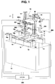
- Fig. 1 is a perspective view of a winding apparatus in its entirety, according to a preferred embodiment of the present invention.
- guide rails 12, 12 are fixed to a base 10 of a winding apparatus.
- These guide rails 12, 12 movably support a guide unit carrier 14 and a nozzle unit carrier 16 and permit displacement thereof in the direction of the arrow X.
- the guide unit carrier 14 can be moved and positioned in the direction of the arrow X by rotating a feed screw 14b through the operation of a motor 14a. Further, the nozzle unit carrier 16 can be moved and positioned by rotating a feed screw 16b through the operation of a motor 16a. The feed screw 16b engages a nut portion 16c of the nozzle unit carrier 16 with both of the feed screw 16b and the nut portion 16c being shown enlarged.
- the guide unit carrier 14 is provided with a strut 18 whose drive section (not shown) can move and position a support member 19 in the direction of the arrow Z (vertical direction).
- the support member 19 is provided with an upper guide unit 301 and a lower guide unit 302 which are arranged parallel with each other in substantially the horizontal direction.
- the upper guide unit 301 is provided with an actuator 301a through the operation of which a hook 301b shown in Fig. 2 removably holds the wire material W in a sandwiching manner.
- the lower guide unit 302 of Fig. 1 is provided with an actuator 302a through the operation of which a hook 302b shown in Fig. 2 can hold the wire material 302b in a sandwiching manner.
- the nozzle unit carrier 16 of Fig. 1 is provided with a strut 30.
- the strut 30 is provided with a nozzle unit support section 31 which can be positioned and moved in the direction of the arrow Z by a drive section 31a comprising a motor.
- the nozzle unit support section 31 is provided with a drive motor 221, a belt 222, a wire material stopper 225 and a nozzle unit 201.
- the belt 222 is passed around a pulley 221a, a pulley 221b and a pulley 221c of the drive motor 221.
- the nozzle unit 201 can be indexed by a predetermined angle in a direction of ⁇ around an axis C.
- the wire material stopper 225 has the function of stopping the supply of the wire material W toward the nozzle unit 201 by the operation of an actuator 226.
- the nozzle unit 201 can be indexed in the direction of the arrow a as described above.
- the nozzle unit 201 is provided with side plates 201a, 201a between which three guide rollers 205, 205 and 204, a top end member 202 and a guide member 203 for leading out the wire material W are arranged.
- the two guide rollers 205 are rotatably provided between the side plates 201a.
- the remaining guide roller 204 is rotatably provided on the side of the top end member 202.
- the top end member 202 corresponds to the top end of the nozzle unit 201 and is provided with a passage 202a for allowing the wire material W to pass therethrough and the guide member 203 is provided at the end of the passage 202a.
- the guide member 203 is made of an abrasion-resistant material, for example, ruby or ceramics so as to serve as a guide member for leading out the wire material W.
- the top end member 202 projects in the horizontal direction and is substantially in the form of a lateral convex cylinder. Accordingly, the nozzle unit 201 has the top end member 202 so that it is, as a whole, in the shape of L.
- the lateral width L of the nozzle unit 201 is smaller than the inner diameter of an opening 21b of the workpiece K shown in Fig. 2.
- the projecting length TH of the guide member 203 is such that the guide member 203 can enter every minor portion of a VLF winding portion B of the workpiece K of Fig. 2 and the diameter DHP of the guide member 203 can also enter every minor portion of the VLF winding portion B.
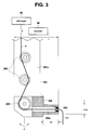
- the wire material W is introduced to the outside from the guide member 203 and is fed to guide member 203 through the passage 202a via the guide rollers 205, 205 and the guide roller 204 as shown in Fig. 3.
- the wire material W is led out from the wire material supply source 43 and the intermediate portion of the wire material is applied with a predetermined tension by a tensioner 44.
- a workpiece support 70 shown in Fig. 2 is provided with a work receiving plate 401 which is a portion supporting the workpiece K in a stabilized state.
- the workpiece K is supported on the receiving plate 401 with the central axis CK thereof extending in the vertical direction.
- the workpiece support 70 can be indexed by a predetermined angle in the direction of the arrow ⁇ by the operation of a rotary section 73.
- the workpiece K is the frame of a deflecting yoke provided in the cathode ray tube of a TV receiver and it has the following structure.
- the workpiece K of Fig. 2 is, for example, a high vision deflecting yoke and is substantially funnel-shaped.
- the opening 21a of the workpiece K is positioned on the fluorescent surface of the cathode ray tube and the smaller opening 21b is arranged on the side of the neck of the cathode ray tube.
- the workpiece K is provided with a plurality of engagement strips 21c and a plurality of winding grooves 21d. Further, the smaller opening 21b is provided with engagement strips 21x. These engagement strips 21c, winding grooves 21d and engagement strips 21x are portions around which a deflection coil is wound.
- the workpiece K is provided with a winding portion B corresponding to a portion where a leakage magnetic field shielding coil (VLF) is formed in the vicinity of the winding grooves 21d.
- VLF leakage magnetic field shielding coil
- a main body supply portion 150 is constructed of the wire material stopper 225, the rotary drive section 160 and the nozzle unit 201.
- the rotary drive section 160 is constructed of the above-mentioned drive motor 221, the belt 222, the pulleys 221a, 221b and 221c.
- a first winding means 300 shown in Fig. 2 is the portion where the winding in the first direction is formed by moving the wire material W in a three-dimensional direction after binding the wire material W about the binding portions of the workpiece K corresponding to the engagement strips 21c and 21x by the nozzle unit 201 for supplying the wire material W from the wire material supply source 43 of Fig. 2 to the workpiece K, the upper guide unit 301 cooperating with the movement of the nozzle unit 201.
- This first winding is the above-described deflection coil.
- a second winding means 400 is the portion where a second winding different from the first winding is formed on the workpiece K by moving the nozzle unit 201 in directions parallel and normal to the axis CK of the workpiece K.
- This second winding is the leakage magnetic field shielding coil (VLF).
- the first winding means 300 is constructed of the nozzle unit 201, the upper guide unit 301, the lower guide unit 302 and the workpiece support 70.
- the second winding means 400 is constructed of the nozzle unit 201 and the workpiece support 70.
- a control section 600 controls the actuators 301a, 302a, the drive section 31a, the drive motor 221, the motors 14a, 16a, the actuator 226 and the operation of the rotary section 73 of Fig. 2.
- This deflection coil is the first winding 450 which is applied on the workpiece K by using the first winding means 300.
- the wire material W of Fig. 3 is applied with a predetermined tensile force by a tensioner 44 lest the wire material W should become loosened while it is fed from the wire material supply source. Then, the wire material W runs along the path 202a via the guide rollers 205, 205 and 204 of the nozzle unit 201 and is led outside from the guide member 203. The wire material W is directed in a substantially L-shaped path at the guide roller 204 and is led out horizontally from the guide member 203.
- the top end W1 of the wire material W is fixedly bound around a pin 77 of Fig. 4. That is, when the nozzle unit support section lowers the nozzle unit 201 in the Z-direction as designated by the arrow, the nozzle unit 201 travels to the opening 21b from the opening 21a of the workpiece K. Then the hook 301b of the upper guide unit fixes the top end of the wire material W in a sandwiching fashion. Then the wire material W is guided toward the rear side of the binding pin 77 and at this stage, the workpiece support 70 is indexed by a predetermined angle in the direction of + ⁇ by the operation of the rotary section 73 whereby the upper guide unit 301 is deemed to have been relatively moved in the direction of + Y of Fig. 4.
- the guide unit 301 is moved in the Z-direction.
- the workpiece support 70 of Fig. 2 is indexed again by a predetermined angle in the direction of - ⁇ whereby the upper guide unit 301 is deemed to have been relatively moved in the -Y direction.
- the wire material W held by the upper guide unit 301 is bound around the binding pin 77.
- the binding of the wire material W around the pin 77 is performed a plurality of times.
- the nozzle unit 201 performs a deflection yoke winding operation in three-dimensional fashion. That is, by the movements of the nozzle unit 201 in the Z and X directions and the movements of the upper and lower guide units 301 and 302, the wire material W forms the three-dimensional first winding 450 passed around the engagement strips 21c and 21x serving as the binding sections of the workpiece K. In this case, by moving the wire material from the nozzle unit 201 in a three-dimensional direction after being bound around the engagement pieces 21c and 21x, the deflection coil 450 as the first winding is formed.
- Fig. 5 there is shown a manner in which the wire material W is bound around the engagement strip 21c through the cooperation with the upper guide unit 301 with the nozzle unit 201 lying above the opening 21a of the workpiece K. Further, when the nozzle unit 201 comes to lie below the openings 21a and 21b, it is possible to bind the wire material W around the engagement strip 21x through the cooperation of the lower guide unit 302 and the nozzle unit 201.
- a circumferential winding 500 may be applied in the winding groove 21d of the workpiece K. That is, when the workpiece support 70 rotates clockwise, for example, by the operation of the rotary section 73, the wire material W extending horizontally from the top end member 202 of the nozzle unit 201 is smoothly wound along the winding groove 21d to form the circumferential winding 500.
- the top end member 202 of the nozzle unit 201 moves to the engagement strip A of the workpiece K and the wire material W passes along the engagement strip A whereby the setting for the initiation of winding of the winding 501 of the leakage magnetic field shielding coil (VLF) to be described hereinbelow is complete.
- VLF leakage magnetic field shielding coil
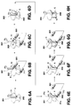
- Figs. 6A through 6H show respective steps involved in forming a saddle type deflection coil on the workpiece K.
- the top end member 202 of the nozzle unit 201 is held horizontal.
- Fig. 6A the top end member 202 of the nozzle unit 201 raises up the wire material W along the direction Z1 from inside the workpiece K and in Fig. 6B, the upper guide unit 301 holds the wire material W. Then, when the workpiece K is rotated by a predetermined angle in the R1 direction, the conditions shown in Figs. 6C and 6D are brought forth and the wire material W is wound along the circumference of the workpiece K.
- the nozzle unit 201 reaches the opening 21b through the opening 21a of the workpiece K and the lower guide unit 302 holds the wire material W. Then, the lower guide unit 302 draws the wire material W outside as shown in Fig. 6F and rotates the workpiece K in the direction of R2 so that the wire material W is wound circumferentially along the neck portion of the workpiece K and finally, the wire material W is wound saddlelike as shown in Fig. 6H.
- the winding of the deflection coil can be wound saddlelike in a simple manner through the cooperation of the upper guide unit 301 with the lower guide unit 302.
- the top end member 202 of the nozzle unit 201 moves down to a point b of the winding portion B (see Fig. 2) of the leakage magnetic field shielding coil (VLF) while it supplies the wire material W.
- the workpiece support 70 is rotated counter-clockwise (in the + ⁇ direction) so that the top end member 202 of the nozzle unit 201 comes to lie outside a point d of the winding portion B.
- the top end member 202 of the nozzle unit 201 moves up in the z-direction to take a position above a point e of the winding portion B.
- the workpiece K rotates clockwise (- ⁇ direction) to allow the top end member 202 to move to a position f of the winding portion B and then the top end member 202 lowers to the initial winding position.
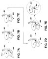
- Figs. 7A to 7E and Figs. 8A to 8E show the steps of performing a leakage magnetic field shielding coil (VFL), respectively.
- VFL leakage magnetic field shielding coil
- the top end member 202 of the nozzle unit 201 binds the wire material W around a pin of the VLF winding portion. That is, the top end member 202 of the nozzle unit 201 goes round the pin 2 to wind the wire material W several times.
- the top end member 202 projecting horizontally from the nozzle unit 201 can come close to the pin and go round the pin so that it is possible to prevent the nozzle unit 201 from running against the engagement strip 21c which forms itself the outer periphery of the workpiece K.
- FIG. 8A through 8E there is shown a manner in which the top end member 202 of the nozzle unit 201 performs a leakage magnetic field shielding coil winding operation around the VLF winding portion B.
- Fig. 8A the wire material W having its one end already wound around the pin 2 of Fig. 7A is positioned at the end of the winding portion B and in Fig. 8B, the nozzle unit 201 goes down in the direction of Z2 so that the wire material W is wound over the first side of the winding portion B.
- the nozzle unit 201 rotates by 90 degrees and moves relative to the workpiece K so that the wire material W is wound along the groove in the second side of the winding portion.
- nozzle unit 201 moves up in the direction of Z1 so that the wire material W is wound around the third side of the winding portion B.
- the wire material W is wound around by a predetermined number of times.
- the nozzle unit 201 makes it possible that the top end member 202 binds and then winds the wire material W around the pin and the winding portion B without running against the projecting portion of the workpiece K.
- nozzle unit 201 having the top end member 202
- the horizontal deflection coil winding operation (called a main winding)
- the wire material binding operation with respect to the pin 2 of Figs. 7A to 7E and the leakage magnetic field shielding coil winding operation shown in Figs. 8A to 8E can be performed efficiently and without causing any trouble of the nozzle unit 201 running against the workpiece K.
- the winding of the leakage magnetic field shielding coil (VLF) is applied to the winding portion B as shown in Fig. 2 thereby completing the winding operation for the leakage magnetic field shielding coil (VFL).
- the winding of the leakage magnetic field shielding coil becomes possible by adding the top end member 202 to the nozzle unit 201 and the winding of the VLF coil can follow on continuously from the winding of the deflection coil.
- the workpiece K may well be held vertically by the workpiece support 70 as shown in Fig. 2. Accordingly, it is possible to perform the deflection coil and VLF coil winding operations in a short time and in a stabilized manner thereby sharply improving the production efficiency of the deflection yoke.
- the present embodiment it is possible to wind the deflection yoke coil and the VLF coil efficiently and unlike the conventional method in which both the deflection coil and VLF coil winding operations are performed by a plurality of winding apparatuses, these different winding operations can be performed by a single apparatus.
- abrasion-resistant guide member 203 on the top end portion of the nozzle unit 201, it is possible to minimize the amount of abrasion of the top end member 202 resulting from the passage of the wire material W so that the life of the nozzle unit 201 can be extended.
- the present invention is not limited to the above-described embodiment.
- the leakage magnetic field shielding coil winding operation is performed after performing the horizontal deflection coil winding but it is of course possible to reverse the order of performing the winding operations.
- the winding apparatus shown in Fig. 9 is provided with two sets of upper guide units 301 and lower guide units 302 which are provided on the strut 18 of the guide unit carrier 14.
- the strut 30 of the nozzle unit carrier 16 is provided with the nozzle unit support 431.
- the nozzle unit support 431 is provided with two nozzle units 201.
- the remaining points of the embodiment of Fig. 9 are similar to those of the embodiment of Fig. 1 so that the description thereof is omitted herein.
Landscapes
- Engineering & Computer Science (AREA)
- Manufacturing & Machinery (AREA)
- Formation Of Various Coating Films On Cathode Ray Tubes And Lamps (AREA)
Abstract
Description
- The present invention relates to a winding apparatus for winding a wire material around a workpiece and more particularly to a winding apparatus and method for forming a deflection coil and a leakage magnetic field shielding coil with respect to, for example, a deflection yoke as a workpiece.
- The deflection yoke as used for a cathode ray tube such as a TV receiver requires a leakage magnetic field shielding coil (VLF) for shielding a leakage magnetic field due to electron beams and a deflection coil for deflecting the electron beams.
- Recently, in performing a winding operation with respect to a deflection yoke, there has been a strong demand for integrally performing the VLF coil winding and the deflection coil winding by a single winding apparatus. This is because of a demand for saving power in the deflection yoke coil winding operation.
- However, it is considered difficult to perform the VLF winding and the deflection coil winding integrally with each other by a single winding apparatus. Generally, for forming a VLF winding, a method is employed which involves winding the wire material around the deflection yoke by a dedicated machine while keeping the deflection yoke horizontal.
- If it is attempted to perform both a VLF winding and a deflection coil winding integrally by a single winding apparatus, a mere combination of a conventional VLF winding apparatus and a conventional deflection coil winding apparatus is complicated in structure such that for example, where the deflection coil winding operation shifts to the VLF winding operation or vice versa, it becomes necessary to change the attitude of the deflecting yoke, for example, from its vertically oriented state to its horizontally oriented state, which results in increasing the number of manhours.
- Conventional apparatus for winding a deflecting yoke is disclosed in U.S. Patent Nos. 5484113 and 5419503. The nozzles used in these prior art techniques make use of rollers or guide members in order to guide an introduced wire material vertically, upper right or left or lower right or left.
- However, by mere use of such rollers or guide members for the nozzle, it is difficult to perform a VLF winding and a deflection coil winding altogether because the wire material introduced from the nozzle can not be guided well to come close to the grooves formed in various minor portions of the deflecting yoke.
- The present invention has been made to eliminate the above-described problems and an object of the present invention is to provide a winding apparatus which is capable of winding a wire material in a variety of ways in different directions while keeping a workpiece such as a deflecting yoke in a certain attitude, and also to provide a winding method using the apparatus.
- The above-described object of the present invention can be achieved by using a winding apparatus which comprises: a nozzle unit for supplying a wire material from a wire material supply source to a workpiece; first winding means for forming a first winding by moving the wire material from the nozzle unit in a three-dimensional direction after binding the wire material around a binding portion of the workpiece through a guide unit cooperating with the movement of the nozzle unit; and second winding means for forming on the workpiece a second winding different from the first winding by moving the nozzle unit in directions parallel and normal to the axis of the workpiece, respectively.
- In the present invention, where the wire material from the wire supply source is wound around the workpiece, the first winding means can form the first winding on the workpiece by binding the wire material from the nozzle unit at the binding portion of the workpiece and then moving it in three-dimensional directions through the cooperation of the nozzle unit and the guide unit.
- Further, the second winding means can form the second winding different from the first winding by moving the nozzle unit in directions parallel and normal to the axis of the workpiece, respectively.
- Where the workpiece is, for example, the frame of the deflecting coil for a cathode ray tube, the first winding corresponds to a deflecting coil and the second winding corresponds to a leakage magnetic field shielding coil. Further, where the first and second windings are formed, it is not necessary to change the attitude of the workpiece.
- In the present invention, the top end of the nozzle unit from which the wire material is introduced is substantially L-shaped with a projection of a size so set as to allow the nozzle to pass along every part of the workpiece. By such arrangement, the top end of the nozzle unit can enter into the minor portions such as grooves, of every part of the workpiece so that the first and second windings can be secured to the corresponding parts of the workpiece, respectively.
- The above-described object of the present invention can be achieved by a winding method for winding a wire material paid out from a wire material supply source, which method is characterized in that a first winding is formed on the workpiece in such a manner that the wire material from the wire material supply source is fed to the workpiece through a nozzle unit and after being bound up around a binding portion of the workpiece, it is moved in a three-dimensional direction through a guide unit cooperating with the movement of the nozzle unit, and a second winding different from the first winding is formed on the workpiece by moving the nozzle unit in directions parallel and normal to the axis of the workpiece.
- The above-described object of the present invention can be achieved by a winding method for winding a wire material paid out from a wire material supply source, which method is characterized in that a second winding is formed on the workpiece by moving a nozzle unit, through which the wire material is fed to the workpiece, in directions parallel and normal to the axis of the workpiece and a first winding different from the second winding is formed on the workpiece in such a manner that the wire material from the nozzle unit is moved in a three-dimensional direction after it is bound up around a binding portion of the workpiece by the nozzle unit and a guide unit cooperating with the movement of the nozzle unit.
-
- Fig. 1 is a perspective view of a winding apparatus in its entirety according to one embodiment of the present invention;
- Fig. 2 is a perspective view showing a nozzle unit carrier, a mechanical portion around a nozzle unit of the wiring apparatus of Fig. 1, a workpiece and a workpiece support.
- Fig. 3 is a view showing basic portions of the nozzle unit;
- Fig. 4 is a diagram showing an initial operation of winding a horizontal deflection coil;
- Fig. 5 is a diagram of one example showing an intermediate state of the horizontal deflection coil winding operation;
- Figs. 6A to 6H are diagrams illustrating in more detail the step of winding the horizontal deflection coil;
- Figs. 7A to 7E are diagrams illustrating an operation of binding one end of a wire material W around a pin before winding a leakage magnetic field shielding coil;
- Figs. 8A to 8E are diagrams illustrating in more detail the step of winding the leakage magnetic field shielding coil; and
- Fig. 9 is a perspective view of a winding apparatus according to another embodiment of the present invention.
- Preferred embodiments of the present invention will now be described with reference to the accompanying drawings.
- It should be noted that although the following embodiments include various kinds of technically preferable limitations since they are practically preferred examples of the present invention, the present invention is not limited to these examples unless specifically described otherwise in the following description.
- Fig. 1 is a perspective view of a winding apparatus in its entirety, according to a preferred embodiment of the present invention. As shown,
guide rails base 10 of a winding apparatus. These guide rails 12, 12 movably support aguide unit carrier 14 and anozzle unit carrier 16 and permit displacement thereof in the direction of the arrow X. - The
guide unit carrier 14 can be moved and positioned in the direction of the arrow X by rotating afeed screw 14b through the operation of amotor 14a. Further, thenozzle unit carrier 16 can be moved and positioned by rotating afeed screw 16b through the operation of amotor 16a. Thefeed screw 16b engages anut portion 16c of thenozzle unit carrier 16 with both of thefeed screw 16b and thenut portion 16c being shown enlarged. - The
guide unit carrier 14 is provided with astrut 18 whose drive section (not shown) can move and position asupport member 19 in the direction of the arrow Z (vertical direction). Thesupport member 19 is provided with anupper guide unit 301 and alower guide unit 302 which are arranged parallel with each other in substantially the horizontal direction. - The
upper guide unit 301 is provided with anactuator 301a through the operation of which ahook 301b shown in Fig. 2 removably holds the wire material W in a sandwiching manner. Similarly, thelower guide unit 302 of Fig. 1 is provided with anactuator 302a through the operation of which ahook 302b shown in Fig. 2 can hold thewire material 302b in a sandwiching manner. - Furthermore, the
nozzle unit carrier 16 of Fig. 1 is provided with astrut 30. Thestrut 30 is provided with a nozzleunit support section 31 which can be positioned and moved in the direction of the arrow Z by adrive section 31a comprising a motor. As shown in Fig. 2, the nozzleunit support section 31 is provided with adrive motor 221, abelt 222, awire material stopper 225 and anozzle unit 201. - The
belt 222 is passed around apulley 221a, apulley 221b and apulley 221c of thedrive motor 221. By operating thedrive motor 221, thenozzle unit 201 can be indexed by a predetermined angle in a direction of α around an axis C. Thewire material stopper 225 has the function of stopping the supply of the wire material W toward thenozzle unit 201 by the operation of anactuator 226. - Next, the
nozzle unit 201 will be described. - As shown in Figs. 2 and 3, the
nozzle unit 201 can be indexed in the direction of the arrow a as described above. Thenozzle unit 201 is provided withside plates guide rollers top end member 202 and aguide member 203 for leading out the wire material W are arranged. - The two
guide rollers 205 are rotatably provided between theside plates 201a. Theremaining guide roller 204 is rotatably provided on the side of thetop end member 202. - The
top end member 202 corresponds to the top end of thenozzle unit 201 and is provided with apassage 202a for allowing the wire material W to pass therethrough and theguide member 203 is provided at the end of thepassage 202a. Theguide member 203 is made of an abrasion-resistant material, for example, ruby or ceramics so as to serve as a guide member for leading out the wire material W. - The
top end member 202 projects in the horizontal direction and is substantially in the form of a lateral convex cylinder. Accordingly, thenozzle unit 201 has thetop end member 202 so that it is, as a whole, in the shape of L. The lateral width L of thenozzle unit 201 is smaller than the inner diameter of an opening 21b of the workpiece K shown in Fig. 2. - In addition, the projecting length TH of the
guide member 203 is such that theguide member 203 can enter every minor portion of a VLF winding portion B of the workpiece K of Fig. 2 and the diameter DHP of theguide member 203 can also enter every minor portion of the VLF winding portion B. - The wire material W is introduced to the outside from the
guide member 203 and is fed to guidemember 203 through thepassage 202a via theguide rollers guide roller 204 as shown in Fig. 3. The wire material W is led out from the wirematerial supply source 43 and the intermediate portion of the wire material is applied with a predetermined tension by atensioner 44. - A
workpiece support 70 shown in Fig. 2 is provided with awork receiving plate 401 which is a portion supporting the workpiece K in a stabilized state. The workpiece K is supported on the receivingplate 401 with the central axis CK thereof extending in the vertical direction. Theworkpiece support 70 can be indexed by a predetermined angle in the direction of the arrow θ by the operation of arotary section 73. - In the present embodiment, the workpiece K is the frame of a deflecting yoke provided in the cathode ray tube of a TV receiver and it has the following structure.
- That is, the workpiece K of Fig. 2 is, for example, a high vision deflecting yoke and is substantially funnel-shaped. When the workpiece K is mounted on the cathode ray tube, the
opening 21a of the workpiece K is positioned on the fluorescent surface of the cathode ray tube and thesmaller opening 21b is arranged on the side of the neck of the cathode ray tube. - The workpiece K is provided with a plurality of engagement strips 21c and a plurality of winding
grooves 21d. Further, thesmaller opening 21b is provided withengagement strips 21x. These engagement strips 21c, windinggrooves 21d andengagement strips 21x are portions around which a deflection coil is wound. - The workpiece K is provided with a winding portion B corresponding to a portion where a leakage magnetic field shielding coil (VLF) is formed in the vicinity of the winding
grooves 21d. - A main
body supply portion 150 is constructed of thewire material stopper 225, therotary drive section 160 and thenozzle unit 201. Therotary drive section 160 is constructed of the above-mentioneddrive motor 221, thebelt 222, thepulleys - Further, a first winding means 300 shown in Fig. 2 is the portion where the winding in the first direction is formed by moving the wire material W in a three-dimensional direction after binding the wire material W about the binding portions of the workpiece K corresponding to the engagement strips 21c and 21x by the
nozzle unit 201 for supplying the wire material W from the wirematerial supply source 43 of Fig. 2 to the workpiece K, theupper guide unit 301 cooperating with the movement of thenozzle unit 201. This first winding is the above-described deflection coil. - Further, a second winding means 400 is the portion where a second winding different from the first winding is formed on the workpiece K by moving the
nozzle unit 201 in directions parallel and normal to the axis CK of the workpiece K. This second winding is the leakage magnetic field shielding coil (VLF). Further, the first windingmeans 300 is constructed of thenozzle unit 201, theupper guide unit 301, thelower guide unit 302 and theworkpiece support 70. Further, the second winding means 400 is constructed of thenozzle unit 201 and theworkpiece support 70. - A
control section 600 controls the actuators 301a, 302a, thedrive section 31a, thedrive motor 221, themotors actuator 226 and the operation of therotary section 73 of Fig. 2. - Next, a method of forming a
deflection coil 450 and a leakage magneticfield shielding coil 501 of the workpiece K as the deflection yoke of Fig. 2 by using the above-described winding apparatus will be described. - First, one example of forming the deflection coil on the workpiece K will be described.
- This deflection coil is the first winding 450 which is applied on the workpiece K by using the first winding
means 300. - The wire material W of Fig. 3 is applied with a predetermined tensile force by a
tensioner 44 lest the wire material W should become loosened while it is fed from the wire material supply source. Then, the wire material W runs along thepath 202a via theguide rollers nozzle unit 201 and is led outside from theguide member 203. The wire material W is directed in a substantially L-shaped path at theguide roller 204 and is led out horizontally from theguide member 203. - The top end W1 of the wire material W is fixedly bound around a
pin 77 of Fig. 4. That is, when the nozzle unit support section lowers thenozzle unit 201 in the Z-direction as designated by the arrow, thenozzle unit 201 travels to theopening 21b from theopening 21a of the workpiece K. Then thehook 301b of the upper guide unit fixes the top end of the wire material W in a sandwiching fashion. Then the wire material W is guided toward the rear side of thebinding pin 77 and at this stage, theworkpiece support 70 is indexed by a predetermined angle in the direction of + θ by the operation of therotary section 73 whereby theupper guide unit 301 is deemed to have been relatively moved in the direction of + Y of Fig. 4. After that, theguide unit 301 is moved in the Z-direction. Theworkpiece support 70 of Fig. 2 is indexed again by a predetermined angle in the direction of -θ whereby theupper guide unit 301 is deemed to have been relatively moved in the -Y direction. Thus, the wire material W held by theupper guide unit 301 is bound around the bindingpin 77. The binding of the wire material W around thepin 77 is performed a plurality of times. - Next, as shown in Fig. 5, when the
nozzle support 31 is operated, thenozzle unit 201 performs a deflection yoke winding operation in three-dimensional fashion. That is, by the movements of thenozzle unit 201 in the Z and X directions and the movements of the upper andlower guide units nozzle unit 201 in a three-dimensional direction after being bound around theengagement pieces deflection coil 450 as the first winding is formed. - In Fig. 5, there is shown a manner in which the wire material W is bound around the
engagement strip 21c through the cooperation with theupper guide unit 301 with thenozzle unit 201 lying above theopening 21a of the workpiece K. Further, when thenozzle unit 201 comes to lie below theopenings engagement strip 21x through the cooperation of thelower guide unit 302 and thenozzle unit 201. - Thus, it is possible to form the so called saddle type three-dimensional first winding (deflection coil) 450.
- Further, a circumferential winding 500 may be applied in the winding
groove 21d of the workpiece K. That is, when theworkpiece support 70 rotates clockwise, for example, by the operation of therotary section 73, the wire material W extending horizontally from thetop end member 202 of thenozzle unit 201 is smoothly wound along the windinggroove 21d to form the circumferential winding 500. - Then, after the formation of the circumferential winding 500 along the winding
groove 21d, thetop end member 202 of thenozzle unit 201 moves to the engagement strip A of the workpiece K and the wire material W passes along the engagement strip A whereby the setting for the initiation of winding of the winding 501 of the leakage magnetic field shielding coil (VLF) to be described hereinbelow is complete. - Now, one example of how the deflection coil is wound saddlelike will be described in further detail with reference to Figs. 6A through 6H.
- Figs. 6A through 6H show respective steps involved in forming a saddle type deflection coil on the workpiece K. The
top end member 202 of thenozzle unit 201 is held horizontal. - In Fig. 6A, the
top end member 202 of thenozzle unit 201 raises up the wire material W along the direction Z1 from inside the workpiece K and in Fig. 6B, theupper guide unit 301 holds the wire material W. Then, when the workpiece K is rotated by a predetermined angle in the R1 direction, the conditions shown in Figs. 6C and 6D are brought forth and the wire material W is wound along the circumference of the workpiece K. - Next, as shown in Fig. 6E, the
nozzle unit 201 reaches theopening 21b through theopening 21a of the workpiece K and thelower guide unit 302 holds the wire material W. Then, thelower guide unit 302 draws the wire material W outside as shown in Fig. 6F and rotates the workpiece K in the direction of R2 so that the wire material W is wound circumferentially along the neck portion of the workpiece K and finally, the wire material W is wound saddlelike as shown in Fig. 6H. - Thus, the winding of the deflection coil can be wound saddlelike in a simple manner through the cooperation of the
upper guide unit 301 with thelower guide unit 302. - In the winding operation for the leakage magnetic field shielding coil (VFL), the
top end member 202 of thenozzle unit 201 moves down to a point b of the winding portion B (see Fig. 2) of the leakage magnetic field shielding coil (VLF) while it supplies the wire material W. Next, theworkpiece support 70 is rotated counter-clockwise (in the +θ direction) so that thetop end member 202 of thenozzle unit 201 comes to lie outside a point d of the winding portion B. - Then, the
top end member 202 of thenozzle unit 201 moves up in the z-direction to take a position above a point e of the winding portion B. - Further, the workpiece K rotates clockwise (-θ direction) to allow the
top end member 202 to move to a position f of the winding portion B and then thetop end member 202 lowers to the initial winding position. - Figs. 7A to 7E and Figs. 8A to 8E show the steps of performing a leakage magnetic field shielding coil (VFL), respectively.
- In Figs. 7A through 7E, the
top end member 202 of thenozzle unit 201 binds the wire material W around a pin of the VLF winding portion. That is, thetop end member 202 of thenozzle unit 201 goes round thepin 2 to wind the wire material W several times. In this case, as shown in Fig. 7E, thetop end member 202 projecting horizontally from thenozzle unit 201 can come close to the pin and go round the pin so that it is possible to prevent thenozzle unit 201 from running against theengagement strip 21c which forms itself the outer periphery of the workpiece K. - Further, in Fig. 8A through 8E, there is shown a manner in which the
top end member 202 of thenozzle unit 201 performs a leakage magnetic field shielding coil winding operation around the VLF winding portion B. - In Fig. 8A, the wire material W having its one end already wound around the
pin 2 of Fig. 7A is positioned at the end of the winding portion B and in Fig. 8B, thenozzle unit 201 goes down in the direction of Z2 so that the wire material W is wound over the first side of the winding portion B. - Then, as shown in Fig. 8C, the
nozzle unit 201 rotates by 90 degrees and moves relative to the workpiece K so that the wire material W is wound along the groove in the second side of the winding portion. - In Fig. 8D, the
nozzle unit 201 moves up in the direction of Z1 so that the wire material W is wound around the third side of the winding portion B. - Lastly, in Fig. 8E, the wire material W is wound around the fourth side of the winding portion B by the rotation of the workpiece K.
- Thus, by repeating the operations in Figs. 8A through 8E, the wire material W is wound around by a predetermined number of times.
- In the above case, it is noted that as shown in Fig. 8E, when the wire material W is continuously wound around the winding portion B, since the
top end member 202 is elongated to project in the horizontal direction, thenozzle unit 201 does not run against theengagement strip 21c of the workpiece K. - The
nozzle unit 201 makes it possible that thetop end member 202 binds and then winds the wire material W around the pin and the winding portion B without running against the projecting portion of the workpiece K. - As described above, as shown in Figs. 6A to 6H, 7A to 7E and 8A to 8E, by the use of one kind of nozzle, that is, the
nozzle unit 201 having thetop end member 202, the horizontal deflection coil winding operation (called a main winding), the wire material binding operation with respect to thepin 2 of Figs. 7A to 7E and the leakage magnetic field shielding coil winding operation shown in Figs. 8A to 8E can be performed efficiently and without causing any trouble of thenozzle unit 201 running against the workpiece K. - By repeating the above operations a predetermined number of times, the winding of the leakage magnetic field shielding coil (VLF) is applied to the winding portion B as shown in Fig. 2 thereby completing the winding operation for the leakage magnetic field shielding coil (VFL).
- As described above, in the present embodiment, the winding of the leakage magnetic field shielding coil (VLF) becomes possible by adding the
top end member 202 to thenozzle unit 201 and the winding of the VLF coil can follow on continuously from the winding of the deflection coil. In this case, the workpiece K may well be held vertically by theworkpiece support 70 as shown in Fig. 2. Accordingly, it is possible to perform the deflection coil and VLF coil winding operations in a short time and in a stabilized manner thereby sharply improving the production efficiency of the deflection yoke. - According to the present embodiment, it is possible to wind the deflection yoke coil and the VLF coil efficiently and unlike the conventional method in which both the deflection coil and VLF coil winding operations are performed by a plurality of winding apparatuses, these different winding operations can be performed by a single apparatus.
- Further, as shown in Fig. 2, by the provision of the excellent abrasion-
resistant guide member 203 on the top end portion of thenozzle unit 201, it is possible to minimize the amount of abrasion of thetop end member 202 resulting from the passage of the wire material W so that the life of thenozzle unit 201 can be extended. - However, the present invention is not limited to the above-described embodiment. In the above embodiment, the leakage magnetic field shielding coil winding operation is performed after performing the horizontal deflection coil winding but it is of course possible to reverse the order of performing the winding operations.
- Further, as another embodiment of the present invention, an example shown in Fig. 9 may be given.
- As will be clear from comparison with the embodiment of Fig. 1, the winding apparatus shown in Fig. 9 is provided with two sets of
upper guide units 301 andlower guide units 302 which are provided on thestrut 18 of theguide unit carrier 14. - The
strut 30 of thenozzle unit carrier 16 is provided with thenozzle unit support 431. Thenozzle unit support 431 is provided with twonozzle units 201. Thus, unlike the embodiment of Fig. 1, by the provision of the twonozzle units 201 and two sets of upper andlower guide units - As described above, according to the present invention, it is possible to wind a wire material in different directions while the workpiece like a deflection yoke keeps its attitude in a certain state.
Claims (5)
- A winding apparatus for winding a wire material (W) from a wire material supply source (43) around a workpiece (K), which apparatus comprises:first winding means (300) comprising a nozzle unit (201) for feeding the wire material paid out from the wire material supply source to the workpiece and a guide unit (301, 302) and operating such that the wire material from the nozzle unit is bound around a binding portion (77) of the workpiece and moved in a three-dimensional direction by the guide unit cooperating with the movement of the nozzle unit, to thereby form a first winding (450) on the workpiece; andsecond winding means (400) for forming on the workpiece a second winding (501) different from the first winding by moving the nozzle unit (201) in directions parallel and normal to the axis of the workpiece.
- A winding apparatus according to Claim 1, wherein the top end (202) of said nozzle unit through which the wire material is fed out projects outward substantially in the shape of L and has a size suitable for allowing it to pass along every part of the workpiece.
- A winding apparatus according to Claim 1, wherein said first winding (450) is a deflection coil of a deflection yoke for use with a cathode ray tube.
- A winding method for winding a wire material (W) paid out from a wire material supply source (43) around a workpiece (K), which method is characterized in that a first winding (450) is formed on the workpiece in such a manner that the wire material from the wire material supply source is fed to the workpiece through a nozzle unit (201) and after being bound up around a binding portion (77) of the workpiece, it is moved in three-dimensional directions through a guide unit (301, 302) cooperating with the movement of the nozzle unit, and a second winding (501) different from the first winding is formed on the workpiece by moving the nozzle unit (201) in directions parallel and normal to the axis of the workpiece.
- A winding method for winding a wire material (W) paid out from a wire material supply source (43) around a workpiece (K), which method is characterized in that a first winding (501) is formed on the workpiece by moving a nozzle unit (201), through which the wire material is fed to the workpiece, in directions parallel and normal to the axis of the workpiece, and a second winding (450) different from the first winding is formed on the workpiece in such a manner that the wire material from the nozzle unit (201) is moved in three-dimensional directions after it is bound up around a binding portion (77) of the workpiece, by the nozzle unit and a guide unit (301, 302) cooperating with the movement of the nozzle unit.
Applications Claiming Priority (3)
| Application Number | Priority Date | Filing Date | Title |
|---|---|---|---|
| JP276857/95 | 1995-09-29 | ||
| JP27685795 | 1995-09-29 | ||
| JP27685795 | 1995-09-29 |
Publications (3)
| Publication Number | Publication Date |
|---|---|
| EP0766282A2 true EP0766282A2 (en) | 1997-04-02 |
| EP0766282A3 EP0766282A3 (en) | 1997-06-04 |
| EP0766282B1 EP0766282B1 (en) | 2002-07-24 |
Family
ID=17575384
Family Applications (1)
| Application Number | Title | Priority Date | Filing Date |
|---|---|---|---|
| EP96402059A Expired - Lifetime EP0766282B1 (en) | 1995-09-29 | 1996-09-26 | Winding apparatus and method |
Country Status (3)
| Country | Link |
|---|---|
| US (1) | US5775626A (en) |
| EP (1) | EP0766282B1 (en) |
| SG (1) | SG43408A1 (en) |
Cited By (1)
| Publication number | Priority date | Publication date | Assignee | Title |
|---|---|---|---|---|
| US6484960B1 (en) * | 1999-10-20 | 2002-11-26 | Sony Corporation | Coil winding machine and method of producing deflection coil |
Families Citing this family (5)
| Publication number | Priority date | Publication date | Assignee | Title |
|---|---|---|---|---|
| JP3177193B2 (en) * | 1997-07-02 | 2001-06-18 | 日特エンジニアリング株式会社 | Winding machine and winding method |
| CN101863119A (en) * | 2010-06-03 | 2010-10-20 | 濮阳市濮光塑胶制品有限公司 | Tool for manufacturing cleaning ball |
| CN102684420B (en) * | 2012-05-05 | 2014-08-06 | 杜瑞 | Internal and external wire-winding type motor stator wire-winding device |
| CN104384393B (en) * | 2014-09-30 | 2016-04-06 | 雷斌蕃 | Fully automatic wire winding machine |
| WO2018221100A1 (en) * | 2017-05-31 | 2018-12-06 | 株式会社小田原エンジニアリング | Nozzle revolving device and winder |
Citations (3)
| Publication number | Priority date | Publication date | Assignee | Title |
|---|---|---|---|---|
| US5191307A (en) * | 1991-02-04 | 1993-03-02 | Murata Mfg. Co., Ltd. | Deflection yoke apparatus |
| EP0582409A1 (en) * | 1992-08-05 | 1994-02-09 | Sony Corporation | Method of winding coils of a deflection yoke and an apparatus for carrying out the same |
| EP0596628A2 (en) * | 1992-11-06 | 1994-05-11 | Sony Corporation | Winding wire around deflection yokes |
Family Cites Families (7)
| Publication number | Priority date | Publication date | Assignee | Title |
|---|---|---|---|---|
| NL7415441A (en) * | 1974-11-27 | 1976-05-31 | Philips Nv | DEFLECTION COIL FOR A CATHOD BREAM TUBE AND METHOD OF MANUFACTURING THE SAME. |
| CH607273A5 (en) * | 1976-06-09 | 1978-11-30 | Meteor Ag | |
| US4217937A (en) * | 1979-02-23 | 1980-08-19 | Gte Products Corporation | Coil winding machine |
| US5088186A (en) * | 1990-03-13 | 1992-02-18 | Valentine Engineering, Inc. | Method of making a high efficiency encapsulated power transformer |
| KR940016421A (en) * | 1992-12-30 | 1994-07-23 | 황선두 | Deflection yoke |
| US5373274A (en) * | 1993-08-23 | 1994-12-13 | Academy Electronic Tube, Incorporated | Deflection yoke with anti-ringing winding core slots |
| JPH07335470A (en) * | 1994-06-06 | 1995-12-22 | Sony Corp | Winding device and winding of coil on work |
-
1996
- 1996-09-25 SG SG1996010676A patent/SG43408A1/en unknown
- 1996-09-25 US US08/719,443 patent/US5775626A/en not_active Expired - Fee Related
- 1996-09-26 EP EP96402059A patent/EP0766282B1/en not_active Expired - Lifetime
Patent Citations (3)
| Publication number | Priority date | Publication date | Assignee | Title |
|---|---|---|---|---|
| US5191307A (en) * | 1991-02-04 | 1993-03-02 | Murata Mfg. Co., Ltd. | Deflection yoke apparatus |
| EP0582409A1 (en) * | 1992-08-05 | 1994-02-09 | Sony Corporation | Method of winding coils of a deflection yoke and an apparatus for carrying out the same |
| EP0596628A2 (en) * | 1992-11-06 | 1994-05-11 | Sony Corporation | Winding wire around deflection yokes |
Cited By (1)
| Publication number | Priority date | Publication date | Assignee | Title |
|---|---|---|---|---|
| US6484960B1 (en) * | 1999-10-20 | 2002-11-26 | Sony Corporation | Coil winding machine and method of producing deflection coil |
Also Published As
| Publication number | Publication date |
|---|---|
| SG43408A1 (en) | 1997-10-17 |
| EP0766282B1 (en) | 2002-07-24 |
| EP0766282A3 (en) | 1997-06-04 |
| US5775626A (en) | 1998-07-07 |
Similar Documents
| Publication | Publication Date | Title |
|---|---|---|
| EP1049237B1 (en) | Winding machine | |
| EP0889491B1 (en) | Winding machine having freely positionable nozzle and winding method therefor | |
| US7934530B2 (en) | Filament winding apparatus | |
| US10944311B2 (en) | Nozzle turning apparatus and winding machine | |
| EP0766282B1 (en) | Winding apparatus and method | |
| EP0582409B1 (en) | Method of winding coils of a deflection yoke and an apparatus for carrying out the same | |
| EP3357847B1 (en) | Yarn winder, spun yarn take-up apparatus, and a method of yarn threading in yarn winder | |
| JP2003169455A (en) | Nozzle holder, nozzle-turning unit, and apparatus and method for wire winding | |
| CN1075241C (en) | Device and method for winding deflection yoke with wire | |
| EP3754822A1 (en) | Wire material winding device and winding method | |
| EP0596628B1 (en) | Winding wire around deflection yokes | |
| US6385826B1 (en) | Sample warper with detector for yarn on yarn guide | |
| JPH09153427A (en) | Method and apparatus for winding | |
| JP3713771B2 (en) | Winding device | |
| JP4088853B2 (en) | Unraveling device | |
| MXPA96004379A (en) | Method and devan apparatus | |
| GB2290089A (en) | Method and apparatus for winding wire coils | |
| JP2002369466A (en) | Winding method and winding device | |
| KR0133643Y1 (en) | S-ring supplying device for electronic gun | |
| JP3613873B2 (en) | Winding device | |
| JP2002313662A (en) | Winding device | |
| JPH0714540U (en) | Alignment winding device for deflection coil | |
| KR0185323B1 (en) | Tension apparatus for coil winding machine | |
| JP2515478Y2 (en) | Deflection yoke winding device | |
| JPS63207433A (en) | Spring forming machine |
Legal Events
| Date | Code | Title | Description |
|---|---|---|---|
| PUAI | Public reference made under article 153(3) epc to a published international application that has entered the european phase |
Free format text: ORIGINAL CODE: 0009012 |
|
| AK | Designated contracting states |
Kind code of ref document: A2 Designated state(s): GB NL |
|
| PUAL | Search report despatched |
Free format text: ORIGINAL CODE: 0009013 |
|
| AK | Designated contracting states |
Kind code of ref document: A3 Designated state(s): GB NL |
|
| 17P | Request for examination filed |
Effective date: 19971121 |
|
| 17Q | First examination report despatched |
Effective date: 19981029 |
|
| GRAG | Despatch of communication of intention to grant |
Free format text: ORIGINAL CODE: EPIDOS AGRA |
|
| GRAG | Despatch of communication of intention to grant |
Free format text: ORIGINAL CODE: EPIDOS AGRA |
|
| GRAG | Despatch of communication of intention to grant |
Free format text: ORIGINAL CODE: EPIDOS AGRA |
|
| GRAH | Despatch of communication of intention to grant a patent |
Free format text: ORIGINAL CODE: EPIDOS IGRA |
|
| GRAH | Despatch of communication of intention to grant a patent |
Free format text: ORIGINAL CODE: EPIDOS IGRA |
|
| RAP1 | Party data changed (applicant data changed or rights of an application transferred) |
Owner name: SONY CORPORATION |
|
| GRAA | (expected) grant |
Free format text: ORIGINAL CODE: 0009210 |
|
| AK | Designated contracting states |
Kind code of ref document: B1 Designated state(s): GB NL |
|
| PG25 | Lapsed in a contracting state [announced via postgrant information from national office to epo] |
Ref country code: NL Free format text: LAPSE BECAUSE OF FAILURE TO SUBMIT A TRANSLATION OF THE DESCRIPTION OR TO PAY THE FEE WITHIN THE PRESCRIBED TIME-LIMIT Effective date: 20020724 |
|
| REG | Reference to a national code |
Ref country code: GB Ref legal event code: FG4D |
|
| PG25 | Lapsed in a contracting state [announced via postgrant information from national office to epo] |
Ref country code: GB Free format text: LAPSE BECAUSE OF NON-PAYMENT OF DUE FEES Effective date: 20021024 |
|
| NLV1 | Nl: lapsed or annulled due to failure to fulfill the requirements of art. 29p and 29m of the patents act | ||
| PLBE | No opposition filed within time limit |
Free format text: ORIGINAL CODE: 0009261 |
|
| STAA | Information on the status of an ep patent application or granted ep patent |
Free format text: STATUS: NO OPPOSITION FILED WITHIN TIME LIMIT |
|
| GBPC | Gb: european patent ceased through non-payment of renewal fee |
Effective date: 20021024 |
|
| 26N | No opposition filed |
Effective date: 20030425 |