EP0766050A2 - Saturateur adiabatique ainsi que procédé de conditionnement d'air - Google Patents
Saturateur adiabatique ainsi que procédé de conditionnement d'air Download PDFInfo
- Publication number
- EP0766050A2 EP0766050A2 EP96650030A EP96650030A EP0766050A2 EP 0766050 A2 EP0766050 A2 EP 0766050A2 EP 96650030 A EP96650030 A EP 96650030A EP 96650030 A EP96650030 A EP 96650030A EP 0766050 A2 EP0766050 A2 EP 0766050A2
- Authority
- EP
- European Patent Office
- Prior art keywords
- air stream
- temperature
- saturator
- water
- air
- Prior art date
- Legal status (The legal status is an assumption and is not a legal conclusion. Google has not performed a legal analysis and makes no representation as to the accuracy of the status listed.)
- Withdrawn
Links
Images


Classifications
-
- F—MECHANICAL ENGINEERING; LIGHTING; HEATING; WEAPONS; BLASTING
- F24—HEATING; RANGES; VENTILATING
- F24F—AIR-CONDITIONING; AIR-HUMIDIFICATION; VENTILATION; USE OF AIR CURRENTS FOR SCREENING
- F24F3/00—Air-conditioning systems in which conditioned primary air is supplied from one or more central stations to distributing units in the rooms or spaces where it may receive secondary treatment; Apparatus specially designed for such systems
- F24F3/12—Air-conditioning systems in which conditioned primary air is supplied from one or more central stations to distributing units in the rooms or spaces where it may receive secondary treatment; Apparatus specially designed for such systems characterised by the treatment of the air otherwise than by heating and cooling
- F24F3/14—Air-conditioning systems in which conditioned primary air is supplied from one or more central stations to distributing units in the rooms or spaces where it may receive secondary treatment; Apparatus specially designed for such systems characterised by the treatment of the air otherwise than by heating and cooling by humidification; by dehumidification
- F24F3/147—Air-conditioning systems in which conditioned primary air is supplied from one or more central stations to distributing units in the rooms or spaces where it may receive secondary treatment; Apparatus specially designed for such systems characterised by the treatment of the air otherwise than by heating and cooling by humidification; by dehumidification with both heat and humidity transfer between supplied and exhausted air
-
- B—PERFORMING OPERATIONS; TRANSPORTING
- B05—SPRAYING OR ATOMISING IN GENERAL; APPLYING FLUENT MATERIALS TO SURFACES, IN GENERAL
- B05B—SPRAYING APPARATUS; ATOMISING APPARATUS; NOZZLES
- B05B16/00—Spray booths
- B05B16/60—Ventilation arrangements specially adapted therefor
-
- F—MECHANICAL ENGINEERING; LIGHTING; HEATING; WEAPONS; BLASTING
- F24—HEATING; RANGES; VENTILATING
- F24F—AIR-CONDITIONING; AIR-HUMIDIFICATION; VENTILATION; USE OF AIR CURRENTS FOR SCREENING
- F24F8/00—Treatment, e.g. purification, of air supplied to human living or working spaces otherwise than by heating, cooling, humidifying or drying
- F24F8/10—Treatment, e.g. purification, of air supplied to human living or working spaces otherwise than by heating, cooling, humidifying or drying by separation, e.g. by filtering
- F24F8/117—Treatment, e.g. purification, of air supplied to human living or working spaces otherwise than by heating, cooling, humidifying or drying by separation, e.g. by filtering using wet filtering
-
- F—MECHANICAL ENGINEERING; LIGHTING; HEATING; WEAPONS; BLASTING
- F24—HEATING; RANGES; VENTILATING
- F24F—AIR-CONDITIONING; AIR-HUMIDIFICATION; VENTILATION; USE OF AIR CURRENTS FOR SCREENING
- F24F6/00—Air-humidification, e.g. cooling by humidification
- F24F6/12—Air-humidification, e.g. cooling by humidification by forming water dispersions in the air
- F24F6/14—Air-humidification, e.g. cooling by humidification by forming water dispersions in the air using nozzles
- F24F2006/146—Air-humidification, e.g. cooling by humidification by forming water dispersions in the air using nozzles using pressurised water for spraying
-
- Y—GENERAL TAGGING OF NEW TECHNOLOGICAL DEVELOPMENTS; GENERAL TAGGING OF CROSS-SECTIONAL TECHNOLOGIES SPANNING OVER SEVERAL SECTIONS OF THE IPC; TECHNICAL SUBJECTS COVERED BY FORMER USPC CROSS-REFERENCE ART COLLECTIONS [XRACs] AND DIGESTS
- Y02—TECHNOLOGIES OR APPLICATIONS FOR MITIGATION OR ADAPTATION AGAINST CLIMATE CHANGE
- Y02A—TECHNOLOGIES FOR ADAPTATION TO CLIMATE CHANGE
- Y02A50/00—TECHNOLOGIES FOR ADAPTATION TO CLIMATE CHANGE in human health protection, e.g. against extreme weather
- Y02A50/20—Air quality improvement or preservation, e.g. vehicle emission control or emission reduction by using catalytic converters
Definitions
- the present invention relates generally to an apparatus and process for continuously providing air at a predetermined temperature and humidity. More specifically, the present invention relates to an adiabatic saturator air supply system for supplying air at predetermined psychrometric conditions.
- Air supply systems are typically made to clean and condition air flowing through buildings, rooms, or equipment. These air systems employ various devices to filter, heat, cool, humidify or dehumidify air, including dry filters, electrostatic precipitators, burners, heating coils, sprayed coils, cooling coils, wetted media, steam injection, and other apparatus. These devices are used in various combinations depending upon ambient conditions and the target conditions. Specifically, these air systems typically require that both temperature and relative humidity be continually monitored in order to assure the desired air quality.
- Relatively specific and stringent psychrometric values may be required of air supply systems such as those used in waterborne and powder paint spray booth applications. This is due to the comparatively narrow window of psychrometric conditions that are acceptable for waterborne and powder paint applications (e.g., about 65°F/60% RH for powder paint, and about 70°F/70% RH for waterborne paint).
- Various techniques have been developed to provide humidity control systems for paint spray booth applications. However, these previous systems have required the monitoring and maintenance of both the desired relative humidity and temperature levels for the air within the controlled system.
- These multi-variable processes require complex control systems to achieve the preselected filtered, psychrometric conditions necessary for the introduction of an air stream into a spray booth.
- These systems or "air supply houses” are also relatively large structures taking approximately one-third of the space required for the spray booth and adding additional floors above the spray booth, thus decreasing the practicality and cost effectiveness of the paint facility.
- paint spray booths require the conditioning and filtering of large volumes of air (e.g., 500,000 cubic feet per minute), with a corresponding expenditure of energy. It is therefore desirable both to recover energy from the exhaust air, and to minimize the air volume required to undergo conditioning.
- Another object of the invention is to provide a system that accomplishes the adiabatic saturation of an air stream without the need for directly measuring relative humidity.
- a further object of the invention is to provide a system that can minimize the flow rate of air requiring conditioning by recirculating processed air within the system.
- Still a further object of the invention is to provide a method for conditioning an air stream that is more economical than existing air control systems.
- an apparatus for conditioning an air stream to provide the air stream to an operation area at desired, predetermined temperature and relative humidity levels includes an adiabatic saturator through which the air stream and water flows. The water intimately mixes with the air stream within the saturator, resulting in an air stream exiting the saturator which is completely saturated with water, which has a temperature equal to the temperature of the water entering the saturator, and which has been scrubbed of particulate contaminants.
- a first temperature sensor is positioned to measure the temperature of the air stream exiting the saturator.
- a heater such as a heating coil or a burner
- a cooling coil is located upstream of the saturator, for selectively heating the air stream or chilling water and pumping the water through a cooling coil to cool the air prior to its entry into the saturator, in response to the temperature measurement from the first temperature sensor, and is useful when the volume of air flow within the conditioning system is not constant.
- a cooling coil is not used since the air can be directly cooled within the saturator.
- the air stream can be reheated after it exits the saturator to increase its temperature and reduce its relative humidity to the desired, predetermined levels.
- a second temperature sensor is positioned to measure the temperature of the air stream downstream of the saturator and after it has been reheated. The reheater is adjustably responsive to the temperature measurement of the second temperature sensor.
- the adiabatic saturator includes a spray tower containing packing elements.
- the packing elements enhance the heat transfer and saturation of the air stream improving the mixing an intimate contact between the water and the air stream within the spray tower.
- a process for conditioning an air stream to provide the air stream to an operation area at desired, predetermined temperature and relative humidity levels also forms a part of the present invention.
- a continuous flow of air and water is maintained through an adiabatic chamber.
- the air stream and the water within the chamber intimately mixes so that the air stream is saturated with water and the temperature of the air stream exiting the chamber is approximately equal to the temperature of the water entering the chamber.
- the temperature of the air stream exiting the saturator is measured with a first temperature sensor.
- the air stream or the water, prior to its entry to the chamber can be selectively heated or chilled, in response to the temperature measurement of the first temperature sensor.
- the air stream can be reheated; the temperature of this air stream can be measured by a second temperature sensor, and the amount of reheating can be selectively controlled to account for changes in the volume of air flow through the system.
- the-amount of reheating is kept at a constant rate if the air flow can be maintained at a relatively constant rate, further minimizing process controls.
- varying proportions of ambient air and air from the operation area can be selectively recirculated to the adiabatic chamber. Also, the water exiting the chamber can be recirculated back through the chamber.
- An air conditioning chamber or apparatus preferably consisting of a packed spray tower, is designated generally as 10 in FIGURE 1.
- the upper portion of air conditioning chamber 10 is in fluid communication with duct 50, which conveys properly conditioned air to an operation area, such as the paint spray operation shown in FIGURE 2 and described below.
- Air conditioning apparatus 10 is an adiabatic saturator, a device in which heat is neither gained or lost. With an adiabatic saturator, the heat of vaporization for the water that is evaporated is supplied by the cooling of the air passing through the saturator. The wet-bulb temperature of the air stream is constant throughout the chamber, and the weight of water evaporated equals the increase in the specific humidity of the air within the chamber. Tower 10 should be constructed to be sufficiently large so that the air stream exiting the chamber will be saturated at the wet-bulb temperature of the air stream entering the chamber.
- Packed spray tower 10 shown in FIGURE 1 accommodates [spelling] a downward flow of water provided by spray nozzles 64 to thereby properly condition the upwardly flowing air mass through the saturator to a prescribed and predetermined temperature and humidity.
- the water flow is recirculated within saturator/tower 10 by pump 18, which continually delivers the water to spray nozzles 64 from holding tank 12.
- pump 18 which continually delivers the water to spray nozzles 64 from holding tank 12.
- the air stream is brought into contact with water for a suitable duration so that the air becomes saturated with moisture (i.e., it has 100% relative humidity), and the wet-bulb temperature of the air stream exiting the tower approximately equals the temperature of the water entering the tower (differing only by radiation and velocity errors that affect the wet-bulb thermometer).
- the air exit stream then contacts heat exchanger 68, which preferably adds a constant amount of heat to the air stream to alter the air stream to the desired psychrometric conditions. Because the heat added to the air exit stream is constant, provided the air stream flow remains constant, process controls are minimized.
- spray tower 10 is preferably preceded by a burner to warm the entering air stream (e.g., heat exchanger 78A), primarily to avoid freezing of the water in winter conditions.
- Heat exchanger 68 is used to warm the air stream exiting the tower to the desired temperature, while simultaneously reducing its relative humidity to the desired value.
- adiabatic saturation is achieved by adjusting the temperature of the inlet air stream to a wet-bulb temperature equal to the temperature of the fluid stream entering the saturator
- adiabatic saturation can be achieved by adjusting the temperature of the fluid stream to equal the wet-bulb temperature of the air stream exiting the saturator. Either process results in an air stream having a known temperature and a known relative humidity without the need for monitoring any parameter other than the temperature of the air stream.
- adiabatic saturation of the supply air takes place in packed spray tower 10 containing packing elements 65.
- the water impacts packing elements 14 within saturator 10, intimately mixing with and "scrubbing" the counter-current air stream. (Cross-streams or even unidirectional streams of air and water can also be used, though a counter-current air stream is preferred, as discussed below.)
- Packed spray tower 10 permits contaminants to be removed from the air stream (they are transferred to the water) while simultaneously conditioning the air stream in the manner described above.
- a demister 66 and a reheater 68 may be positioned downstream of adiabatic saturator 10.
- the scrubbing fluid to be used should be water, since the use of fluids other than water would require the measurement of humidity, in contravention to the teaching of the present invention.
- the packing elements 65 within spray tower 10 may be a plastic material of the type disclosed in U.S. Patent No. 4,668,442 and sold as NuPac® Tower Packing-by Lantec Products Inc. of Agoura Hills, California. This packing element is currently preferred because of its high scrubbing efficiency and its high resistance to fouling or plugging.
- the packing elements enhance the heat transfer and humidification effects of the water on the air stream within the spray tower, for as the water contacts the packing elements, it surrounds and wets them, increasing the surface area of the water which is in direct, intimate contact with the flowing air stream.
- a packed bed length of 4 feet has been found to permit inlet air ranging in temperature from 0°F to 100°F to be properly conditioned for introduction into a paint spray booth.
- the capital cost for this filtering and air conditioning system has been estimated to be between about $1.00 and $1.50 per cubic foot/minute.
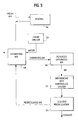
- an integrated paint spray booth and air conditioning system is designated generally as 15 and is schematically illustrated.
- the system 15 includes as its basic components a spray booth housing 20, a scrubber chamber 30, a filtering chamber 40, a duct 50, an air conditioning apparatus 10, and an air circulating means, such as blower or fan 70.
- Saturator 10 receives recirculating air from the spray booth operation through inlet 52 located in a lower portion of saturator 10.
- a fresh air stream may also be introduced via filter 63 into saturator 62 and mixes with the circulating air in the system and the downward flow of water.
- the spray booth housing 20 defines a paint application zone 22 through which the automotive bodies or other articles to be painted pass sequentially.
- Housing 20 includes opposing side walls 24 and a top 26 and bottom 28 each of which includes one or more air passages to accommodate a downward flow of the air through the paint application zone 22.
- the scrubber chamber 30 extends longitudinally beneath the paint spray booth housing 20 and includes an inlet comprised of a plurality of longitudinally spaced cylinders 34 which receive air discharged from the spray booth, and terminate in a scrubber outlet 36.
- the air flow exiting scrubber chamber 30, now laden with various contaminant particles acquired within operation area 32 of the paint spray booth enters into filtering chamber 40 and passes through a plurality of filter elements 42.
- a discharge plenum 46 Downstream of air filters 42, on the side of the filtering chamber opposite to the scrubber chamber, is a discharge plenum 46 in fluid communication with duct 50.
- Inlet 52 permits the air stream to flow up through saturator 10 to duct 50, which extends a sufficient vertical height to permit the circulation of air to the top of the spray booth 20.
- the air supply stream After the air supply stream is adiabatically saturated, the air supply stream then passes through demister 66, which removes water droplets carried by the air stream. Next, the air supply stream passes through heat exchanger 68 to bring the air to the desired temperature and relative humidity, thus placing the air stream within the desired psychrometric "window.” The air stream then circulates through duct work 50 by means of fan 70, which also acts to offset any pressure drop that occurs within the tower. Fan 70 may then draw the air stream into a supply plenum 48 and through additional bag filters, if necessary. Supply plenum 48 provides for the even introduction of the air stream across operation area 32 during operation.
- An exhaust duct 80 may also be employed, and is preferably located to communicate with the system at the plenum disposed between filtering chamber 40 and the inlet 52 to duct 50.
- An exhaust fan 82 discharges the exhausted air to atmosphere.
- Automatically controlled dampers 61 and 84 can be employed to balance the air flow in the system by adjusting the quantity of fresh air introduced into the system and/or the quantity of system air that is exhausted. Alternatively, additional treatment of the air upon its exit from operation area 32 may be necessary.
- duct 50 may be required to be extremely long for a given application.
- a packed spray tower having a bed length of four feet is acceptable for treating air ranging from approximately 32°F and 0% relative humidity to approximately 90°F and 100% relative humidity.
- a comparable unpacked tower would be required to be over 25 feet in length. This results in undesired increases in capital costs, weight and operating space.
- one temperature sensor 27 is positioned immediately downstream of the saturator and upstream of reheater 68. Temperature sensor 27 thus monitors the saturated air temperature; in a winter condition (for example), either the air entering the saturator or the water in or supplied to the saturator can be heated to obtain the desired temperature of the air stream, depending on the input from sensor 27.
- a second temperature sensor 29 can be positioned within duct 50 immediately downstream of reheater 68; this temperature measurement permits the adjustment of the amount of heat from the reheater, ensuring an adequate-amount of reheat, given changes in the volume of air flow. (Volumetric air flow changes can occur within the system for various reasons, including changes in the operation, the amount of recirculation of the air stream, the damper mechanisms, etc.) With these two simple and inexpensive temperature sensors 27 and 29, which need only be ordinary thermometers, complete psychrometric control over the air stream is obtained. Because the temperature of the incoming ambient air can also vary during the day, in either summer of winter conditions, and the air stream volume can also vary, constant temperature monitoring of the air stream exiting the saturator should be performed.
- All or part of the air stream can be recirculated and introduced back into packed tower 10, or it can be removed through exhaust duct 80 by exhaust fan 82, where the air can be processed for further treatment of (e.g.) volatile organic compounds.
- the amount of recirculation necessary for the system is dependant upon at least two factors. First, in extremely cold weather conditions, it may be necessary to heat fresh air entering saturator 10. An increased amount of recirculated air would minimize the energy requirements for heating the fresh air stream to be introduced into the saturator. Minimizing the portion of the air stream being removed through the exhaust also minimizes the energy requirements and cost of any secondary air treatment processes that might be used.
- a second counterbalancing factor to be considered in determining the amount of recirculated air to be used is the nature and amount of contaminants built up within the system. Some applications may not require extensive human exposure to the operation area. Thus, there may not be an overriding concern of taking in "fresh" air. However, by increasing the amount of recirculated air within the system, the amount of potential contaminants within the air stream increases, possibly creating potential environmental or safety risks within the system, given the application. Approximately 0-90% by volume air stream recirculation is preferred for the particular application of a paint spray booth, to ensure non-explosive conditions for the paint solvent.
- a constant flow of air is brought into tower 10 at a temperature of 40°F and 10% relative humidity (shown as point A), and air is pretreated with a burner so that it is heated to approximately 106°F and a wet bulb temperature of 60°F (shown as point B).
- point B a wet bulb temperature of 60°F
- the air is then saturated, and exits tower 10 at approximately 60°F and 100% relative humidity (point C).
- This exit air stream then passes through heat exchanger 68, which provides the air stream with a constant amount of reheat (approximately 3 Btu/lb dry air) to produce the desired air stream at approximately 70% relative humidity and 70°F (point D).
- a constant flow of air is brought into tower 10 at a temperature of 90°F and 85% relative humidity (shown as point E), and the water in tower 10 is treated with a chiller (not shown) so that the exit air stream is brought down to a temperature of 60°F and a relative humidity of 100% (shown as point C).
- the exit air steam then passes through heat exchanger 24, which provides the air stream with a constant amount of reheat to produce the resulting air stream at 70% relative humidity and 70°F (point D).
- Chilling the water avoids the need for a separate cooling coil during summer to cool air prior to its introduction into the tower. Rather, the present system preferably compensates for the air inlet temperature using chilled water within the system, thus creating a more efficient heat exchange and reducing the capital cost of the system. Alternatively, the air stream may be cooled prior to saturation, but cooling the air is less thermodynamically efficient than chilling the water.
- the use of counter-current air and fluid streams i.e., streams in parallel but opposite directions
- the air stream exiting saturator 10, as well as the fluid stream entering saturator 10, have a constant temperature across the cross-section of each exiting stream. This results in a constant temperature profile for the exiting air stream and avoids temperature stratification of the exiting streams (i.e., different temperatures in different regions along the cross-section of the exiting stream, which occurs when the air and fluid stream directions are normal to each other). Temperature stratification can result in certain regions of the air stream being outside the desired psychrometric conditions (although the average psychrometric levels of the overall air stream will be within the desired levels). Temperature stratification may therefore require the use of further devices to mix the air.
- an initial step in the process involves saturating an air stream by scrubbing the air stream with a fluid such as water maintained at the desired wet-bulb temperature sought for the air stream.
- the air stream is preferably reheated with a predetermined, constant amount of heat (see block 50).
- the air stream is introduced into an operation area (block 52).
- a portion of the "used" air stream can now be recirculated back to be saturated (block 48).
- fresh air can be heated (block 56) by a heating coil or burner prior to saturating the air.
- the fresh air can be chilled (e.g. with water) prior to saturating it, or (preferably) the fluid can be chilled (block 59).
- reheating of the air stream exiting the saturator may not be required (i.e., 100% RH may be within the psychrometric window given the application).
- a reheater can be used but a temperature sensor positioned downstream of the reheater need not be used, since volumetric changes in the air stream may not need to be accounted for in a given application.
Landscapes
- Engineering & Computer Science (AREA)
- Chemical & Material Sciences (AREA)
- Combustion & Propulsion (AREA)
- Mechanical Engineering (AREA)
- General Engineering & Computer Science (AREA)
- Air Conditioning Control Device (AREA)
- Central Air Conditioning (AREA)
- Air Humidification (AREA)
Applications Claiming Priority (2)
| Application Number | Priority Date | Filing Date | Title |
|---|---|---|---|
| US50810795A | 1995-07-27 | 1995-07-27 | |
| US508107 | 1995-07-27 |
Publications (2)
| Publication Number | Publication Date |
|---|---|
| EP0766050A2 true EP0766050A2 (fr) | 1997-04-02 |
| EP0766050A3 EP0766050A3 (fr) | 1998-01-07 |
Family
ID=24021413
Family Applications (1)
| Application Number | Title | Priority Date | Filing Date |
|---|---|---|---|
| EP96650030A Withdrawn EP0766050A3 (fr) | 1995-07-27 | 1996-07-26 | Saturateur adiabatique ainsi que procédé de conditionnement d'air |
Country Status (3)
| Country | Link |
|---|---|
| EP (1) | EP0766050A3 (fr) |
| JP (1) | JPH09119687A (fr) |
| CA (1) | CA2181510A1 (fr) |
Cited By (10)
| Publication number | Priority date | Publication date | Assignee | Title |
|---|---|---|---|---|
| WO2002077537A1 (fr) * | 2001-03-27 | 2002-10-03 | The Procter & Gamble Company | Procede et appareil pour l'epuration de l'air |
| US6484417B2 (en) * | 2001-02-02 | 2002-11-26 | Wenger Manufacturing, Inc. | Dryer apparatus and dryer control system |
| EP1269092A2 (fr) * | 1999-02-12 | 2003-01-02 | Silicon Valley Group, Inc. | Systemes et procedes de regulation d'ambiance |
| US7052791B2 (en) | 2000-07-28 | 2006-05-30 | Hydrogenics Corporation | Apparatus for humidification and temperature control of incoming fuel cell process gas |
| US7051801B1 (en) * | 2000-07-28 | 2006-05-30 | Hydrogenics Corporation | Method and apparatus for humidification and temperature control of incoming fuel cell process gas |
| WO2009106256A1 (fr) | 2008-02-29 | 2009-09-03 | Dürr Systems GmbH | Installation de peinture |
| CN102205292A (zh) * | 2011-06-01 | 2011-10-05 | 吉安锐迈管道配件有限公司 | 多工位自动恒温喷涂系统 |
| CN102914000A (zh) * | 2012-11-07 | 2013-02-06 | 刘拴强 | 新风加湿空调机组 |
| CN105042687A (zh) * | 2015-06-30 | 2015-11-11 | 成都赋阳技术开发有限公司 | 一种节能型空气消毒过滤器 |
| EP2913297A4 (fr) * | 2012-10-26 | 2016-06-29 | Mitsubishi Heavy Ind Ltd | Saturateur et système de reformage de gaz naturel équipé de celui-ci |
Families Citing this family (2)
| Publication number | Priority date | Publication date | Assignee | Title |
|---|---|---|---|---|
| JP4948070B2 (ja) * | 2006-07-28 | 2012-06-06 | 三機工業株式会社 | 空調制御方法および空気調和機 |
| CN114687178A (zh) * | 2020-12-30 | 2022-07-01 | 广东美的白色家电技术创新中心有限公司 | 衣物处理装置 |
Citations (2)
| Publication number | Priority date | Publication date | Assignee | Title |
|---|---|---|---|---|
| US4222319A (en) | 1977-11-14 | 1980-09-16 | Schweitzer Industrial Corporation | Paint spray booth with flooded floor |
| US4668442A (en) | 1985-09-12 | 1987-05-26 | Lang Ko C | Column packing |
Family Cites Families (4)
| Publication number | Priority date | Publication date | Assignee | Title |
|---|---|---|---|---|
| US3951625A (en) * | 1972-08-30 | 1976-04-20 | Follette Donald T | Air conditioning apparatus |
| JPS5649828A (en) * | 1979-09-28 | 1981-05-06 | Kanto Seiki Kk | Device for producing air having equal dew point |
| DE3042659A1 (de) * | 1980-11-12 | 1982-06-16 | Adolf 7251 Weissach Berkmann | Verfahren zum elektrostatischen auftragen von loesungsmittelfreien pulverfoermigen stoffen, insbesondere farbstoffen, auf werkstuecken und pulverbeschichtunganlage |
| EP0661504B1 (fr) * | 1993-08-16 | 1999-04-21 | National Research Development Corporation | Un système d'humidification du type cellulaire destiné à l'usage industriel |
-
1996
- 1996-07-18 CA CA002181510A patent/CA2181510A1/fr not_active Abandoned
- 1996-07-26 EP EP96650030A patent/EP0766050A3/fr not_active Withdrawn
- 1996-07-29 JP JP8216056A patent/JPH09119687A/ja active Pending
Patent Citations (2)
| Publication number | Priority date | Publication date | Assignee | Title |
|---|---|---|---|---|
| US4222319A (en) | 1977-11-14 | 1980-09-16 | Schweitzer Industrial Corporation | Paint spray booth with flooded floor |
| US4668442A (en) | 1985-09-12 | 1987-05-26 | Lang Ko C | Column packing |
Cited By (20)
| Publication number | Priority date | Publication date | Assignee | Title |
|---|---|---|---|---|
| US7389813B2 (en) | 1999-02-12 | 2008-06-24 | Asml Holding N.V. | Systems and methods for controlling local environment |
| EP1269092A2 (fr) * | 1999-02-12 | 2003-01-02 | Silicon Valley Group, Inc. | Systemes et procedes de regulation d'ambiance |
| EP1269092A4 (fr) * | 1999-02-12 | 2003-06-25 | Silicon Valley Group | Systemes et procedes de regulation d'ambiance |
| US6966364B1 (en) | 1999-02-12 | 2005-11-22 | Asml Holding N.V. | Systems and methods for controlling local environment |
| US7261150B2 (en) | 2000-07-28 | 2007-08-28 | Hydrogenics Corporation | Apparatus for humidification and temperature control of incoming fuel cell process gas |
| US7052791B2 (en) | 2000-07-28 | 2006-05-30 | Hydrogenics Corporation | Apparatus for humidification and temperature control of incoming fuel cell process gas |
| US7051801B1 (en) * | 2000-07-28 | 2006-05-30 | Hydrogenics Corporation | Method and apparatus for humidification and temperature control of incoming fuel cell process gas |
| US6484417B2 (en) * | 2001-02-02 | 2002-11-26 | Wenger Manufacturing, Inc. | Dryer apparatus and dryer control system |
| US6843835B2 (en) | 2001-03-27 | 2005-01-18 | The Procter & Gamble Company | Air cleaning apparatus and method for cleaning air |
| US7147692B2 (en) | 2001-03-27 | 2006-12-12 | The Procter & Gamble Company | Air cleaning apparatus and method for cleaning air |
| WO2002077537A1 (fr) * | 2001-03-27 | 2002-10-03 | The Procter & Gamble Company | Procede et appareil pour l'epuration de l'air |
| WO2009106256A1 (fr) | 2008-02-29 | 2009-09-03 | Dürr Systems GmbH | Installation de peinture |
| CN101959614A (zh) * | 2008-02-29 | 2011-01-26 | 杜尔系统有限公司 | 喷漆设备 |
| CN101959614B (zh) * | 2008-02-29 | 2013-07-24 | 杜尔系统有限公司 | 喷漆设备 |
| CN102205292A (zh) * | 2011-06-01 | 2011-10-05 | 吉安锐迈管道配件有限公司 | 多工位自动恒温喷涂系统 |
| EP2913297A4 (fr) * | 2012-10-26 | 2016-06-29 | Mitsubishi Heavy Ind Ltd | Saturateur et système de reformage de gaz naturel équipé de celui-ci |
| US9638367B2 (en) | 2012-10-26 | 2017-05-02 | Mitsubishi Heavy Industries, Ltd. | Saturator and natural gas reforming system provided with same |
| CN102914000A (zh) * | 2012-11-07 | 2013-02-06 | 刘拴强 | 新风加湿空调机组 |
| CN105042687A (zh) * | 2015-06-30 | 2015-11-11 | 成都赋阳技术开发有限公司 | 一种节能型空气消毒过滤器 |
| CN105042687B (zh) * | 2015-06-30 | 2018-02-23 | 东莞市华生益环保净化科技有限公司 | 一种节能型空气消毒过滤器 |
Also Published As
| Publication number | Publication date |
|---|---|
| CA2181510A1 (fr) | 1997-01-28 |
| EP0766050A3 (fr) | 1998-01-07 |
| JPH09119687A (ja) | 1997-05-06 |
Similar Documents
| Publication | Publication Date | Title |
|---|---|---|
| US4367787A (en) | Air conditioning apparatus and method for paint spray booths | |
| US5425902A (en) | Method for humidifying air | |
| EP0766050A2 (fr) | Saturateur adiabatique ainsi que procédé de conditionnement d'air | |
| US4494596A (en) | Method and apparatus for conditioning air temperature and humidity | |
| US5620503A (en) | Humidifier and method for humidifying air | |
| US6129285A (en) | System and method for air humidification | |
| US4687686A (en) | Spray booth with climate regulation system | |
| AU753010B2 (en) | Dehumidifier system | |
| AU679071B2 (en) | Air quality-temperature controlled central conditioner and multi-zoned conditioning | |
| US6203859B1 (en) | Method of drying substrates and use thereof | |
| US6432367B1 (en) | Indoor air quality gas phase return air cleaner | |
| US5746650A (en) | Integrated paint spray booth and air conditioning system and process | |
| KR850007870A (ko) | 가변풍량식 공기조화 시스템 | |
| US5408838A (en) | Method and apparatus for conditioning unrecycled ambient air | |
| Kabeel | Dehumidification and humidification process of desiccant solution by air injection | |
| US20220152520A1 (en) | Apparatus And Method For Solvent Recovery From Drying Process | |
| Elsarrag et al. | Design guidelines and performance study on a structured packed liquid desiccant air-conditioning system | |
| JP4583637B2 (ja) | 空気浄化空調装置 | |
| US4634455A (en) | Process and apparatus for dehumidification of gaseous media | |
| JPH08105637A (ja) | 空調装置 | |
| GB2465693A (en) | Method of conditioning exterior air for a spray booth | |
| JPH0237245A (ja) | 空気調和機の運転制御装置 | |
| JP2000291994A (ja) | 空調方法 | |
| CA1264995A (fr) | Cabine de pistolage a systeme de controle de l'ambiance | |
| AU2005202670A1 (en) | Dehumidifier system |
Legal Events
| Date | Code | Title | Description |
|---|---|---|---|
| PUAI | Public reference made under article 153(3) epc to a published international application that has entered the european phase |
Free format text: ORIGINAL CODE: 0009012 |
|
| AK | Designated contracting states |
Kind code of ref document: A2 Designated state(s): AT BE CH DE ES FI FR GB IE IT LI LU NL PT SE |
|
| PUAL | Search report despatched |
Free format text: ORIGINAL CODE: 0009013 |
|
| AK | Designated contracting states |
Kind code of ref document: A3 Designated state(s): AT BE CH DE ES FI FR GB IE IT LI LU NL PT SE |
|
| STAA | Information on the status of an ep patent application or granted ep patent |
Free format text: STATUS: THE APPLICATION IS DEEMED TO BE WITHDRAWN |
|
| 18D | Application deemed to be withdrawn |
Effective date: 19980708 |