EP0766030A2 - Direct-coupled solenoid valve - Google Patents
Direct-coupled solenoid valve Download PDFInfo
- Publication number
- EP0766030A2 EP0766030A2 EP96306696A EP96306696A EP0766030A2 EP 0766030 A2 EP0766030 A2 EP 0766030A2 EP 96306696 A EP96306696 A EP 96306696A EP 96306696 A EP96306696 A EP 96306696A EP 0766030 A2 EP0766030 A2 EP 0766030A2
- Authority
- EP
- European Patent Office
- Prior art keywords
- valve
- armature
- iron core
- length
- direct
- Prior art date
- Legal status (The legal status is an assumption and is not a legal conclusion. Google has not performed a legal analysis and makes no representation as to the accuracy of the status listed.)
- Granted
Links
- XEEYBQQBJWHFJM-UHFFFAOYSA-N Iron Chemical group [Fe] XEEYBQQBJWHFJM-UHFFFAOYSA-N 0.000 claims abstract description 29
- 239000012530 fluid Substances 0.000 claims description 4
- 238000007789 sealing Methods 0.000 description 12
- 229920003002 synthetic resin Polymers 0.000 description 4
- 239000000057 synthetic resin Substances 0.000 description 4
- 239000000463 material Substances 0.000 description 3
- 238000004519 manufacturing process Methods 0.000 description 2
- 229920001875 Ebonite Polymers 0.000 description 1
- 229930182556 Polyacetal Natural products 0.000 description 1
- 239000004952 Polyamide Substances 0.000 description 1
- 230000000712 assembly Effects 0.000 description 1
- 238000000429 assembly Methods 0.000 description 1
- 239000000919 ceramic Substances 0.000 description 1
- 239000011248 coating agent Substances 0.000 description 1
- 238000000576 coating method Methods 0.000 description 1
- 230000003247 decreasing effect Effects 0.000 description 1
- 230000000881 depressing effect Effects 0.000 description 1
- 239000013013 elastic material Substances 0.000 description 1
- 239000000696 magnetic material Substances 0.000 description 1
- 229920002647 polyamide Polymers 0.000 description 1
- 229920006324 polyoxymethylene Polymers 0.000 description 1
- 229920005989 resin Polymers 0.000 description 1
- 239000011347 resin Substances 0.000 description 1
Images

Classifications
-
- F—MECHANICAL ENGINEERING; LIGHTING; HEATING; WEAPONS; BLASTING
- F16—ENGINEERING ELEMENTS AND UNITS; GENERAL MEASURES FOR PRODUCING AND MAINTAINING EFFECTIVE FUNCTIONING OF MACHINES OR INSTALLATIONS; THERMAL INSULATION IN GENERAL
- F16K—VALVES; TAPS; COCKS; ACTUATING-FLOATS; DEVICES FOR VENTING OR AERATING
- F16K31/00—Actuating devices; Operating means; Releasing devices
- F16K31/02—Actuating devices; Operating means; Releasing devices electric; magnetic
- F16K31/06—Actuating devices; Operating means; Releasing devices electric; magnetic using a magnet, e.g. diaphragm valves, cutting off by means of a liquid
- F16K31/0603—Multiple-way valves
- F16K31/0624—Lift valves
- F16K31/0627—Lift valves with movable valve member positioned between seats
-
- F—MECHANICAL ENGINEERING; LIGHTING; HEATING; WEAPONS; BLASTING
- F16—ENGINEERING ELEMENTS AND UNITS; GENERAL MEASURES FOR PRODUCING AND MAINTAINING EFFECTIVE FUNCTIONING OF MACHINES OR INSTALLATIONS; THERMAL INSULATION IN GENERAL
- F16K—VALVES; TAPS; COCKS; ACTUATING-FLOATS; DEVICES FOR VENTING OR AERATING
- F16K31/00—Actuating devices; Operating means; Releasing devices
- F16K31/02—Actuating devices; Operating means; Releasing devices electric; magnetic
-
- G—PHYSICS
- G05—CONTROLLING; REGULATING
- G05D—SYSTEMS FOR CONTROLLING OR REGULATING NON-ELECTRIC VARIABLES
- G05D16/00—Control of fluid pressure
- G05D16/20—Control of fluid pressure characterised by the use of electric means
- G05D16/2006—Control of fluid pressure characterised by the use of electric means with direct action of electric energy on controlling means
- G05D16/2013—Control of fluid pressure characterised by the use of electric means with direct action of electric energy on controlling means using throttling means as controlling means
- G05D16/2024—Control of fluid pressure characterised by the use of electric means with direct action of electric energy on controlling means using throttling means as controlling means the throttling means being a multiple-way valve
-
- Y—GENERAL TAGGING OF NEW TECHNOLOGICAL DEVELOPMENTS; GENERAL TAGGING OF CROSS-SECTIONAL TECHNOLOGIES SPANNING OVER SEVERAL SECTIONS OF THE IPC; TECHNICAL SUBJECTS COVERED BY FORMER USPC CROSS-REFERENCE ART COLLECTIONS [XRACs] AND DIGESTS
- Y10—TECHNICAL SUBJECTS COVERED BY FORMER USPC
- Y10T—TECHNICAL SUBJECTS COVERED BY FORMER US CLASSIFICATION
- Y10T137/00—Fluid handling
- Y10T137/5109—Convertible
- Y10T137/5283—Units interchangeable between alternate locations
-
- Y—GENERAL TAGGING OF NEW TECHNOLOGICAL DEVELOPMENTS; GENERAL TAGGING OF CROSS-SECTIONAL TECHNOLOGIES SPANNING OVER SEVERAL SECTIONS OF THE IPC; TECHNICAL SUBJECTS COVERED BY FORMER USPC CROSS-REFERENCE ART COLLECTIONS [XRACs] AND DIGESTS
- Y10—TECHNICAL SUBJECTS COVERED BY FORMER USPC
- Y10T—TECHNICAL SUBJECTS COVERED BY FORMER US CLASSIFICATION
- Y10T137/00—Fluid handling
- Y10T137/8593—Systems
- Y10T137/86493—Multi-way valve unit
- Y10T137/86574—Supply and exhaust
- Y10T137/86622—Motor-operated
-
- Y—GENERAL TAGGING OF NEW TECHNOLOGICAL DEVELOPMENTS; GENERAL TAGGING OF CROSS-SECTIONAL TECHNOLOGIES SPANNING OVER SEVERAL SECTIONS OF THE IPC; TECHNICAL SUBJECTS COVERED BY FORMER USPC CROSS-REFERENCE ART COLLECTIONS [XRACs] AND DIGESTS
- Y10—TECHNICAL SUBJECTS COVERED BY FORMER USPC
- Y10T—TECHNICAL SUBJECTS COVERED BY FORMER US CLASSIFICATION
- Y10T137/00—Fluid handling
- Y10T137/8593—Systems
- Y10T137/86493—Multi-way valve unit
- Y10T137/86574—Supply and exhaust
- Y10T137/8667—Reciprocating valve
- Y10T137/86686—Plural disk or plug
Definitions
- This invention relates to direct-coupled solenoid valves whose valve member is directly opened and closed by the armature of the solenoid control segment.
- valve member of the main valve segment and the armature of the solenoid control segment must be of such size that the valve member and armature come into contact with certainty.
- valve members of the main valve segments have different lengths or stop at different points at the end of the stroke, therefore, multiple solenoid control segments having armatures of correspondingly different sizes have been required.
- An object of this invention is to provide an armature having an iron core whose length is adjustable to the length of the valve member and the stop position at the end of the stroke in a direct-coupled solenoid valve whose armature in the solenoid control segment directly opens and closes the valve member in the main valve segment.
- Another object of this invention is to provide an armature having a core whose length is adjustable as required so that one solenoid control segment can be used with multiple main valve segments whose valve members having different lengths or stopping at different points at the end of the stroke.
- the protrusion of the length setting member from the iron core is adjustable.
- Fig. 1 is a longitudinal cross-sectional view of a direct-coupled solenoid valve embodying the principle of this invention.
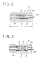
- Fig. 2 is a longitudinal cross-sectional view of an armature in Fig. 1.
- Fig. 3 is a longitudinal cross-sectional view of another embodiment of the armature.
- Figs. 1 and 2 show a direct-coupled solenoid valve 1 which comprises a main valve segment 2 and a solenoid control segment 3.
- a valve casing 5 making up the main valve segment 2 has a supply port P to pass compressed air or other hydraulic fluid, output ports A and B disposed on both sides thereof, and discharge ports EA and EB on both sides of the output ports. These ports open into a valve duct 6 axially in the order mentioned.
- One end of the valve duct 6 is closed by a closing member 8, while the other end is closed by the solenoid control segment 3.
- Reference numeral 7 designates a snap ring to fasten the closing member 8, 8a a sealing member fitted around the closing member 8, and 9 a sealing member sealing the space between the valve casing 5 and the solenoid control segment 3.
- a movable valve member 10 in the valve duct 6 comprises a valve stem 11 having an axial through hole 12 in the center there, poppet type valve sealing members 13a, 13b, 14a and 14b fitted around the valve stem 11, and guide rings 15 fitted around both ends of the valve stem 11.
- the valve sealing members 13a and 13b open and close the passages between the supply port P and the output ports A and B and the valve sealing members 14a and 14b open and close the passages between the output ports A and B and the discharge ports EA and EB.
- the spring chamber 16 at the other end of the valve member 10 communicates with a space 20 between the valve body 5 and the solenoid control segment 3 by means of the through hole 12 in the valve stem 11 and a passageway 18b provided in the intermediate member 18 and with the discharge ports EA and EB by means of the notches (not shown) provided in a part of the outer surface of the guide rings 15.
- the magnetic frame 23 is covered with a coating 29 of synthetic resin or other similar material and hermetically attached to one side of the valve body 5 with bolts or other fastening means not shown. Seal rings 28 hermetically seal the space between the bobbin 22 and the magnetic sheet 24 and between the center hole in the bobbin 22 and the armature 26.
- the center hole 30 in the iron core 27a has a smaller-diameter bore 30a at the end thereof closer to the stator 26.
- a pressing member 32 whose tip comes into contact with the stator 26 is slidably inserted in the end of the smaller-diameter bore 30a.
- the pressing member 32 has a smaller-diameter part 32a that is fitted in the smaller-diameter bore 30a.
- the length of the smaller-diameter part 32a is equal to the length of the protrusion from the smaller-diameter bore 30a toward the stator 26 when the pressing member 32 comes into contact with a step adjoining the smaller-diameter bore 30a at one end of the center hole 30 (see Fig. 2).
- the length setting member 27b determines the core length L of the armature 27 required for switching the valve member 10 in conjunction with the iron core 27a.
- the length setting member 27b is cylindrical and fixed in position by tightly pressing into the end of the center hole 30 closer to the valve member 10. A proper length of the tip protrudes from the center hole to come into contact with the valve member 10 through the intermediate member 18.
- the distance L between the forward end of the length setting member 27b and the rear end of the iron core 27a is set as the length of the iron core of the armature 27.
- the core length L of the iron core can be freely changed by changing the protrusion of the length setting member 27b.
- the length setting member 27b may be made of a magnetic material similar to the iron core 27b or synthetic resin, ceramic or other nonmagnetic materials.
- Reference numeral 37 designates a manual operation mechanism that moves the armature 27 toward the stator 26 by depressing an operation button 37a, and 38 a printed circuit board for providing an electrical connection between an external power supply and the terminal of the exciting coil 21.
- the length setting member 27b is fastened in the center hole 30 in the iron core 27 and, therefore, the protrusion thereof is unadjustable.
- the core length L of the armature 41 can be freely adjusted by stopping the length setting member 41b, which is movable along the axis of the armature 41, at a desired position.
- the length setting member 41b may be fixed at a desired position by bolts or other suitable fastening means so that the length setting member 41b does make unnecessary movements under the impact produced by the switching of the armature or other causes.
Abstract
Description
- This invention relates to direct-coupled solenoid valves whose valve member is directly opened and closed by the armature of the solenoid control segment.
- A direct-coupled solenoid valve of known type comprises a main valve segment having multiple ports to pass a hydraulic fluid, a valve duct into which said ports open in an axial sequence, and a valve member movably fitted in the valve duct and opening and closing the passages between said ports, and a solenoid control segment having an armature operated by the on-off action of an exciting coil and directly opening and closing the valve member.
- When the main valve and solenoid control segment segments of a direct-coupled solenoid valve of the type described above are connected together, the armature contacts one end of the valve member, either directly or through a suitable intermediate member, and the motion of the armature is directly transmitted to the valve member.
- Therefore, the valve member of the main valve segment and the armature of the solenoid control segment must be of such size that the valve member and armature come into contact with certainty. When the valve members of the main valve segments have different lengths or stop at different points at the end of the stroke, therefore, multiple solenoid control segments having armatures of correspondingly different sizes have been required.
- The need to use solenoid control segments and, in particular, armatures of different sizes has introduced considerable complications in the design and manufacture of solenoid valves and inconveniences in their handling.
- Besides, the armatures requiring high dimensional accuracy have been difficult and costly to design and manufacture.
- An object of this invention is to provide an armature having an iron core whose length is adjustable to the length of the valve member and the stop position at the end of the stroke in a direct-coupled solenoid valve whose armature in the solenoid control segment directly opens and closes the valve member in the main valve segment.
- Another object of this invention is to provide an armature having a core whose length is adjustable as required so that one solenoid control segment can be used with multiple main valve segments whose valve members having different lengths or stopping at different points at the end of the stroke.
- Still another object of this invention is to provide an inexpensive and reasonably designed armature of a direct-coupled solenoid valve by providing multiple functions to the member that determines the length of the iron core and incorporating an integral return mechanism therein.
- To achieve the above objects, a direct-coupled solenoid valve according to this invention comprises a main valve segment having multiple ports to pass a hydraulic fluid, a valve duct into which said ports open in an axial sequence, and a valve member movably fitted in the valve duct and opening and closing the passages between said ports, and a solenoid control segment having an armature operated by the on-off action of an exciting coil and directly opening and closing the valve member. The armature in the solenoid control segment comprises an iron core and a length setting member attached thereto, and the iron core and the length setting member jointly set the size of the iron core to the desired one.
- In an embodiment of this invention, the length setting member is attached to one end of the center hole in the iron core, with the tip of the length setting member protruding therefrom and contacting the end of the valve member, either directly or through an intermediate member.
- It is preferable that a pressing member whose tip comes into contact with the stator is movably accommodated in the other end of the center hole of the iron core and a return spring is between the pressing member and the length setting member.
- It is also preferable that the protrusion of the length setting member from the iron core is adjustable.
- The invention will now be further described by way of example with reference to the accompanying drawings in which:
- Fig. 1 is a longitudinal cross-sectional view of a direct-coupled solenoid valve embodying the principle of this invention.
- Fig. 2 is a longitudinal cross-sectional view of an armature in Fig. 1.
- Fig. 3 is a longitudinal cross-sectional view of another embodiment of the armature.
- Figs. 1 and 2 show a direct-coupled solenoid valve 1 which comprises a
main valve segment 2 and a solenoid control segment 3. - A valve casing 5 making up the
main valve segment 2 has a supply port P to pass compressed air or other hydraulic fluid, output ports A and B disposed on both sides thereof, and discharge ports EA and EB on both sides of the output ports. These ports open into avalve duct 6 axially in the order mentioned. One end of thevalve duct 6 is closed by a closing member 8, while the other end is closed by the solenoid control segment 3. Reference numeral 7 designates a snap ring to fasten the closing member 8, 8a a sealing member fitted around the closing member 8, and 9 a sealing member sealing the space between the valve casing 5 and the solenoid control segment 3. - A
movable valve member 10 in thevalve duct 6 comprises avalve stem 11 having an axial through hole 12 in the center there, poppet typevalve sealing members valve stem 11, andguide rings 15 fitted around both ends of thevalve stem 11. When thevalve stem 11 moves axially in thevalve duct 6, thevalve sealing members 13a and 13b open and close the passages between the supply port P and the output ports A and B and thevalve sealing members 14a and 14b open and close the passages between the output ports A and B and the discharge ports EA and EB. - A
valve spring 17 that urges thevalve member 10 toward the solenoid control segment 3 is compressed in a spring chamber 16 between thevalve member 10 and the closing member 8. - The valve sealing
members guide rings 15 are made of polyamide, polyacetal or other resin. - An
intermediate member 18 that indirectly and cushioning brings thevalve member 10 and thearmature 27 into contact thearmature 27 is attached to one end of thevalve member 10 that is closer to the solenoid control segment 3. Theintermediate member 18 is a cylindrical member made of synthetic resin, hard rubber or other similar material and has a push-in tip 18a having a radial elasticity provided by means of multiple axial notches. The push-in tip 18a is elastically pressed in one end of the through hole 12 in thevalve stem 11. - The
intermediate member 18 is used as an aid when the space between thevalve member 10 andarmature 27 is too large to bring them into direct contact. Therefore, thevalve member 10 and thearmature 27 may be brought into direct contact with each other without using theintermediate member 18, depending on the space therebetween. - The spring chamber 16 at the other end of the
valve member 10 communicates with aspace 20 between the valve body 5 and the solenoid control segment 3 by means of the through hole 12 in thevalve stem 11 and apassageway 18b provided in theintermediate member 18 and with the discharge ports EA and EB by means of the notches (not shown) provided in a part of the outer surface of theguide rings 15. - The solenoid control segment 3 comprises a
bobbin 22 wound with anexciting coil 21, amagnetic frame 23 and amagnetic sheet 24 surrounding thebobbin 22, astator 26 inserted into one end of the center hole in thebobbin 22 and fastened to themagnetic frame 23 with abolt 25, and anarmature 27 slidably inserted in the center hole in the bobbin. - The
magnetic frame 23 is covered with acoating 29 of synthetic resin or other similar material and hermetically attached to one side of the valve body 5 with bolts or other fastening means not shown. Seal rings 28 hermetically seal the space between thebobbin 22 and themagnetic sheet 24 and between the center hole in thebobbin 22 and thearmature 26. - The
armature 27 comprises a cylindricalhollow iron core 27a having acenter hole 30 and alength setting member 27b attached to the tip of theiron core 27a, as shown in Fig. 2. An axially extendinggroove 31 is formed in the outer surface of theiron core 27a, with the depth of the groove decreasing toward thespace 20 in themain valve segment 2. - The
center hole 30 in theiron core 27a has a smaller-diameter bore 30a at the end thereof closer to thestator 26. Apressing member 32 whose tip comes into contact with thestator 26 is slidably inserted in the end of the smaller-diameter bore 30a. The pressingmember 32 has a smaller-diameter part 32a that is fitted in the smaller-diameter bore 30a. The length of the smaller-diameter part 32a is equal to the length of the protrusion from the smaller-diameter bore 30a toward thestator 26 when thepressing member 32 comes into contact with a step adjoining the smaller-diameter bore 30a at one end of the center hole 30 (see Fig. 2). - The
length setting member 27b determines the core length L of thearmature 27 required for switching thevalve member 10 in conjunction with theiron core 27a. Thelength setting member 27b is cylindrical and fixed in position by tightly pressing into the end of thecenter hole 30 closer to thevalve member 10. A proper length of the tip protrudes from the center hole to come into contact with thevalve member 10 through theintermediate member 18. The distance L between the forward end of thelength setting member 27b and the rear end of theiron core 27a is set as the length of the iron core of thearmature 27. The core length L of the iron core can be freely changed by changing the protrusion of thelength setting member 27b. - The
length setting member 27b may be made of a magnetic material similar to theiron core 27b or synthetic resin, ceramic or other nonmagnetic materials. - A
return spring 34 having a greater urging force than thevalve spring 17 is compressed between thepressing member 32 and thelength setting member 27b to urge thearmature 27 toward thevalve member 10 at all times. - Thus, the
length setting member 27b has functions to determine the core length L of thearmature 27, press thevalve member 10 in contact therewith, and serve as a support for thereturn spring 34. With thepressing member 32 and returnspring 34 integrally built in, thearmature 27 is inexpensive and reasonably designed. This permits easier handling and assembling than the conventional assemblies in which individual parts are separately attached to the solenoid control segment 3. -
Reference numeral 37 designates a manual operation mechanism that moves thearmature 27 toward thestator 26 by depressing an operation button 37a, and 38 a printed circuit board for providing an electrical connection between an external power supply and the terminal of theexciting coil 21. - When no electric current is passed through the
exciting coil 21, the tip of the smaller-diameter part 32a of thepressing member 32 comes into contact with thestator 26 and thearmature 27 is returned by the urging force of thereturn spring 34, as indicated by the lower half of thearmature 27 and thevalve member 10 in Fig. 1. Therefore, thevalve sealing members 13a and 13b cut off the passage between the supply port P and the output port A and open the passage between the supply port P and the output port B, while thevalve sealing members 14a and 14b open the passage between the output port A and the discharge port EA and cut off the passage between the output port B and the discharge port EB. - When an electric current is passed through the
exciting coil 21, thearmature 27 is attracted to thestator 26 against the urging force of thereturn spring 34, as indicated by the upper part of thearmature 27 and thevalve member 10 in Fig. 1. With thevalve member 10 urged to the right in the figure by the force of thevalve spring 17, thevalve sealing members 13a and 13b open the passage between the supply port P and the output port A and cut off the passage between the supply port P and the output port B, while thevalve sealing members 14a and 14b cut off the passage between the output port A and the discharge port Ea and open the passage between the output port B and the discharge port EB. - Because the core length L of the
armature 27 is determined by theiron core 27a and thelength setting member 27b, theiron core 27a itself does not require very high dimensional accuracy. The core length L can be accurately determined by determining the protrusion of thelength setting member 27b accurately. When joining together themain valve segment 2 and the solenoid control segment 3, thearmature 27 can be brought into contact with thevalve member 10 securely by adjusting the core length L according to the length and the stop position at the end of the stroke of thevalve member 10. - Because the core length L of one
armature 27 can be varied according to thevalve member 10, one solenoid control segment 3 can be used with multiplemain valve segments 2 withvalve members 10 having different length and stop positions at the end of the stroke. - In the
armature 27 of the embodiment des cribed above, thelength setting member 27b is fastened in thecenter hole 30 in theiron core 27 and, therefore, the protrusion thereof is unadjustable. However, it is possible to modify the embodiment by providing alength setting member 27b movable along the axis of theiron core 27b that permits the adjustment of the protrusion thereof. This permits free adjustment of the core length L of thearmature 27. - Fig. 3 shows an
armature 41 having alength setting member 41b whose protrusion is freely adjustable. Internal threads are cut on the inner surface of thecenter hole 42 in aniron core 41a, while external threads are cut on the outer surface of thelength setting member 41b. Thus, thelength setting member 41b freely moves back and forth in thecenter hole 42. - Therefore, the core length L of the
armature 41 can be freely adjusted by stopping thelength setting member 41b, which is movable along the axis of thearmature 41, at a desired position. Thelength setting member 41b may be fixed at a desired position by bolts or other suitable fastening means so that thelength setting member 41b does make unnecessary movements under the impact produced by the switching of the armature or other causes. - Because the other parts and actions of the
armature 41 are substantially the same as those of the first embodiment described earlier, similar parts are designated by similar reference numerals, with detailed description omitted. - When the protrusion of the length setting member is freely adjustable, the core length of the armature can be easily and accurately set and adjusted. For example, pressure balance between two sets of
valve sealing members valve member 10 can be easily adjusted when required. - While the main valve segment in the embodiments described above is a five-port valve, a three-port valve or a four-port valve having common discharge ports can be used as well.
- As described above, a direct-coupled solenoid valve according to this invention adjusts and sets the core length by a length setting member attached to an armature. Hence, the core length can be accurately determined according to the length or the stop position at the end of the stroke of the valve member in the main valve segment even if the iron core does not have very high dimensional accuracy. This permits bringing the armature into contact with the valve member with certainty.
- Because, in addition, the core length L of one armature can be varied according to the valve member, one solenoid control segment can be used with multiple main valve segments with valve members having different lengths or stop positions at the end of the stroke.
Claims (4)
- A direct-coupled solenoid valve comprising: a main valve segment having multiple ports to pass a hydraulic fluid, a valve duct into which the ports open in an axial sequence, and a valve member movably fitted in the valve duct and opening and closing the passages between said ports;a solenoid control segment having an armature operated by the on-off action of an exciting coil and directly opening and closing the valve member;an armature in the solenoid control segment having an iron core and a length setting member attached thereto that jointly determine the length of the iron core.
- A direct-coupled solenoid valve according to claim 1, in which the length setting member of the armature is attached to one end of the center hole in the iron core so that a tip thereof protrudes therefrom and comes into contact with one end of the valve member either directly or through an intermediate member.
- A direct-coupled solenoid valve according to claim 1 or Claim 2, in which a pressing member whose tip comes into contact with the stator is movably accommodated in the other end of the center hole in the iron core and a return spring is compressed between the pressing member and the length setting member.
- A direct-coupled solenoid valve according to any preceding claim , in which the protrusion of the length setting member from the iron core is freely adjustable.
Applications Claiming Priority (3)
| Application Number | Priority Date | Filing Date | Title |
|---|---|---|---|
| JP7273578A JPH0989142A (en) | 1995-09-27 | 1995-09-27 | Direct-acting electromagnetic valve |
| JP27357895 | 1995-09-27 | ||
| JP273578/95 | 1995-09-27 |
Publications (3)
| Publication Number | Publication Date |
|---|---|
| EP0766030A2 true EP0766030A2 (en) | 1997-04-02 |
| EP0766030A3 EP0766030A3 (en) | 1997-05-07 |
| EP0766030B1 EP0766030B1 (en) | 2001-12-05 |
Family
ID=17529759
Family Applications (1)
| Application Number | Title | Priority Date | Filing Date |
|---|---|---|---|
| EP96306696A Expired - Lifetime EP0766030B1 (en) | 1995-09-27 | 1996-09-16 | Direct-coupled solenoid valve |
Country Status (6)
| Country | Link |
|---|---|
| US (1) | US5785299A (en) |
| EP (1) | EP0766030B1 (en) |
| JP (1) | JPH0989142A (en) |
| KR (1) | KR100216972B1 (en) |
| DE (1) | DE69617591T2 (en) |
| TW (1) | TW341302U (en) |
Cited By (2)
| Publication number | Priority date | Publication date | Assignee | Title |
|---|---|---|---|---|
| DE19710173A1 (en) * | 1997-03-12 | 1998-09-17 | Itt Mfg Enterprises Inc | Pressure control valve |
| EP1094261A3 (en) * | 1999-10-18 | 2002-10-30 | Smc Corporation | Solenoid valve |
Families Citing this family (15)
| Publication number | Priority date | Publication date | Assignee | Title |
|---|---|---|---|---|
| US5975488A (en) * | 1995-11-15 | 1999-11-02 | Mannesmann Rexroth Ag | Lifting magnet arrangement |
| US5954235A (en) * | 1998-08-20 | 1999-09-21 | Schroeder; Alfred Augustus | Dispensing valve mounting assembly |
| IT1308779B1 (en) * | 1999-07-02 | 2002-01-10 | Elasis Sistema Ricerca Fiat | DEVICE FOR ADJUSTING THE DELIVERY PRESSURE OF A PUMP, SUITABLE FOR FUEL SUPPLY TO A COMBUSTION ENGINE |
| US7246787B2 (en) * | 2003-12-19 | 2007-07-24 | Kumar Viraraghavan S | Solenoid valve assembly |
| JP2008503694A (en) * | 2004-06-21 | 2008-02-07 | ロバートショウ コントロールズ カンパニー | Variable flow valve |
| JP4695453B2 (en) * | 2005-07-29 | 2011-06-08 | 株式会社豊田中央研究所 | Directional control valve |
| US7806140B2 (en) | 2006-04-18 | 2010-10-05 | Robertshaw Controls Company | Power saving locking coil |
| DE102010025175A1 (en) * | 2010-06-25 | 2011-12-29 | Pierburg Gmbh | Infinitely adjustable pressure control valve |
| DE102011055281B3 (en) * | 2011-11-11 | 2013-02-21 | Pierburg Gmbh | Valve device for a hydraulic circuit and oil pump control arrangement |
| CN104500782B (en) * | 2014-05-28 | 2016-09-21 | 苏州雷姆斯汽车工程有限公司 | A kind of multistage hydraulic regulating slide valve core body |
| CA2963499A1 (en) * | 2014-12-04 | 2016-06-09 | Halliburton Energy Services, Inc. | Telemetry module with push only gate valve action |
| EP3153700A1 (en) * | 2015-10-08 | 2017-04-12 | Continental Automotive GmbH | Valve assembly for an injection valve, injection valve and method for assembling an injection valve |
| CN108547995A (en) * | 2018-05-10 | 2018-09-18 | 北京特种机械研究所 | One kind being suitable for hydraulic damper solenoid valve |
| US11022231B2 (en) * | 2018-12-14 | 2021-06-01 | Marotta Controls, Inc. | Solenoid valve |
| CN111306333B (en) * | 2020-03-01 | 2023-05-16 | 浙江人一阀门制造有限公司 | Safety valve |
Citations (4)
| Publication number | Priority date | Publication date | Assignee | Title |
|---|---|---|---|---|
| DE2050620B2 (en) * | 1970-10-15 | 1971-12-23 | Baldi, Otello, 7054 Korb | GUIDE TUBE FOR A SOLENOID VALVE |
| DE2340304A1 (en) * | 1973-08-09 | 1975-02-20 | Itt Ind Gmbh Deutsche | Multi-way valves to form pressure medium distribution system - valve body has opposite even surfaces with in-and outlets |
| US3952774A (en) * | 1975-01-24 | 1976-04-27 | General Gas Light Company | Electrically operated mini-valve |
| EP0385286A2 (en) * | 1989-02-28 | 1990-09-05 | Lectron Products, Inc. | Variable force solenoid pressure regulator for electronic transmission controller |
Family Cites Families (7)
| Publication number | Priority date | Publication date | Assignee | Title |
|---|---|---|---|---|
| CA698160A (en) * | 1964-11-17 | Eldima Ag | Glandless solenoid valve | |
| US1822668A (en) * | 1927-02-23 | 1931-09-08 | O F Jordan Co | Electromagnetic valve |
| US4530486A (en) * | 1983-02-09 | 1985-07-23 | City Of Hope National Medical Center | Valve |
| US4750704A (en) * | 1983-12-21 | 1988-06-14 | Robert W. Brundage | Solenoid controlled fluid flow valve |
| US4783009A (en) * | 1987-04-27 | 1988-11-08 | Brunswick Corporation | Calibration adjustment of electromagnetic fuel injectors |
| US4834337A (en) * | 1988-04-04 | 1989-05-30 | William J. Chorkey | Solenoid operated valve with solenoid wattage adjustment means |
| US5092365A (en) * | 1991-03-18 | 1992-03-03 | Mac Valves, Inc. | Valve with adjustable valve seat |
-
1995
- 1995-09-27 JP JP7273578A patent/JPH0989142A/en active Pending
-
1996
- 1996-04-05 TW TW085204878U patent/TW341302U/en unknown
- 1996-09-16 DE DE69617591T patent/DE69617591T2/en not_active Expired - Fee Related
- 1996-09-16 KR KR1019960040213A patent/KR100216972B1/en not_active IP Right Cessation
- 1996-09-16 EP EP96306696A patent/EP0766030B1/en not_active Expired - Lifetime
- 1996-09-20 US US08/717,192 patent/US5785299A/en not_active Expired - Fee Related
Patent Citations (4)
| Publication number | Priority date | Publication date | Assignee | Title |
|---|---|---|---|---|
| DE2050620B2 (en) * | 1970-10-15 | 1971-12-23 | Baldi, Otello, 7054 Korb | GUIDE TUBE FOR A SOLENOID VALVE |
| DE2340304A1 (en) * | 1973-08-09 | 1975-02-20 | Itt Ind Gmbh Deutsche | Multi-way valves to form pressure medium distribution system - valve body has opposite even surfaces with in-and outlets |
| US3952774A (en) * | 1975-01-24 | 1976-04-27 | General Gas Light Company | Electrically operated mini-valve |
| EP0385286A2 (en) * | 1989-02-28 | 1990-09-05 | Lectron Products, Inc. | Variable force solenoid pressure regulator for electronic transmission controller |
Cited By (3)
| Publication number | Priority date | Publication date | Assignee | Title |
|---|---|---|---|---|
| DE19710173A1 (en) * | 1997-03-12 | 1998-09-17 | Itt Mfg Enterprises Inc | Pressure control valve |
| US6309030B1 (en) | 1997-03-12 | 2001-10-30 | Continental Teves Ag & Co., Ohg | Pressure control valve |
| EP1094261A3 (en) * | 1999-10-18 | 2002-10-30 | Smc Corporation | Solenoid valve |
Also Published As
| Publication number | Publication date |
|---|---|
| KR100216972B1 (en) | 1999-09-01 |
| TW341302U (en) | 1998-09-21 |
| EP0766030A3 (en) | 1997-05-07 |
| US5785299A (en) | 1998-07-28 |
| DE69617591T2 (en) | 2002-08-01 |
| JPH0989142A (en) | 1997-03-31 |
| KR970016246A (en) | 1997-04-28 |
| EP0766030B1 (en) | 2001-12-05 |
| DE69617591D1 (en) | 2002-01-17 |
Similar Documents
| Publication | Publication Date | Title |
|---|---|---|
| US5785299A (en) | Direct-coupled solenoid valves | |
| US5535783A (en) | Balanced type direct-acting electromagnetic valve | |
| US3921670A (en) | Magnetically operated valve with spider armature | |
| US5509439A (en) | Electromagnetically controlled operating device in particular for valves and electrohydraulic applications | |
| US6772791B2 (en) | Directly operated pneumatic valve having an air assist return | |
| US6619616B1 (en) | Solenoid valve device | |
| KR100465124B1 (en) | Flow Rate Control Valve | |
| US5318071A (en) | High-speed three-way solenoid valve for pressurized fluid, such as compressed air circuits | |
| US6192937B1 (en) | Pilot operated pneumatic valve | |
| EP1463890B1 (en) | Pilot operated pneumatic valve | |
| KR20070026209A (en) | A pilot controlled pulse valve | |
| US5711347A (en) | Double solenoid latching ball valve with a hollow ball | |
| US5503185A (en) | Electromagnetic reversing valve | |
| MXPA95005076A (en) | Two-position three-way solenoid valve. | |
| US4658231A (en) | Actuating magnet with enlarged plunger pole piece | |
| US4337794A (en) | Solenoid valve assembly | |
| KR100476246B1 (en) | Proportional pressure control valve | |
| US5651530A (en) | Electromagnetically operated pressure switching valve | |
| US5918856A (en) | Electropneumatic valve | |
| US6184766B1 (en) | Solenoid valve | |
| JP4704388B2 (en) | solenoid valve | |
| GB2186666A (en) | Low leakage solenoid valve | |
| JP7455053B2 (en) | solenoid valve | |
| AU2002346023B2 (en) | Pilot operated pneumatic valve | |
| JPS638346B2 (en) |
Legal Events
| Date | Code | Title | Description |
|---|---|---|---|
| PUAI | Public reference made under article 153(3) epc to a published international application that has entered the european phase |
Free format text: ORIGINAL CODE: 0009012 |
|
| PUAL | Search report despatched |
Free format text: ORIGINAL CODE: 0009013 |
|
| 17P | Request for examination filed |
Effective date: 19960927 |
|
| AK | Designated contracting states |
Kind code of ref document: A2 Designated state(s): DE FR GB IT |
|
| AK | Designated contracting states |
Kind code of ref document: A3 Designated state(s): DE FR GB IT |
|
| 17Q | First examination report despatched |
Effective date: 19990830 |
|
| GRAG | Despatch of communication of intention to grant |
Free format text: ORIGINAL CODE: EPIDOS AGRA |
|
| GRAG | Despatch of communication of intention to grant |
Free format text: ORIGINAL CODE: EPIDOS AGRA |
|
| GRAH | Despatch of communication of intention to grant a patent |
Free format text: ORIGINAL CODE: EPIDOS IGRA |
|
| GRAH | Despatch of communication of intention to grant a patent |
Free format text: ORIGINAL CODE: EPIDOS IGRA |
|
| GRAA | (expected) grant |
Free format text: ORIGINAL CODE: 0009210 |
|
| AK | Designated contracting states |
Kind code of ref document: B1 Designated state(s): DE FR GB IT |
|
| REG | Reference to a national code |
Ref country code: GB Ref legal event code: IF02 |
|
| REF | Corresponds to: |
Ref document number: 69617591 Country of ref document: DE Date of ref document: 20020117 |
|
| PG25 | Lapsed in a contracting state [announced via postgrant information from national office to epo] |
Ref country code: GB Free format text: LAPSE BECAUSE OF NON-PAYMENT OF DUE FEES Effective date: 20020916 |
|
| PLBE | No opposition filed within time limit |
Free format text: ORIGINAL CODE: 0009261 |
|
| STAA | Information on the status of an ep patent application or granted ep patent |
Free format text: STATUS: NO OPPOSITION FILED WITHIN TIME LIMIT |
|
| 26N | No opposition filed | ||
| PG25 | Lapsed in a contracting state [announced via postgrant information from national office to epo] |
Ref country code: DE Free format text: LAPSE BECAUSE OF NON-PAYMENT OF DUE FEES Effective date: 20030401 |
|
| GBPC | Gb: european patent ceased through non-payment of renewal fee |
Effective date: 20020916 |
|
| PG25 | Lapsed in a contracting state [announced via postgrant information from national office to epo] |
Ref country code: FR Free format text: LAPSE BECAUSE OF NON-PAYMENT OF DUE FEES Effective date: 20030603 |
|
| REG | Reference to a national code |
Ref country code: FR Ref legal event code: ST |
|
| PG25 | Lapsed in a contracting state [announced via postgrant information from national office to epo] |
Ref country code: IT Free format text: LAPSE BECAUSE OF NON-PAYMENT OF DUE FEES Effective date: 20050916 |