EP0385286A2 - Variable force solenoid pressure regulator for electronic transmission controller - Google Patents
Variable force solenoid pressure regulator for electronic transmission controller Download PDFInfo
- Publication number
- EP0385286A2 EP0385286A2 EP90103495A EP90103495A EP0385286A2 EP 0385286 A2 EP0385286 A2 EP 0385286A2 EP 90103495 A EP90103495 A EP 90103495A EP 90103495 A EP90103495 A EP 90103495A EP 0385286 A2 EP0385286 A2 EP 0385286A2
- Authority
- EP
- European Patent Office
- Prior art keywords
- assembly
- valve
- fluid
- chamber
- spool valve
- Prior art date
- Legal status (The legal status is an assumption and is not a legal conclusion. Google has not performed a legal analysis and makes no representation as to the accuracy of the status listed.)
- Granted
Links
Images

Classifications
-
- F—MECHANICAL ENGINEERING; LIGHTING; HEATING; WEAPONS; BLASTING
- F16—ENGINEERING ELEMENTS AND UNITS; GENERAL MEASURES FOR PRODUCING AND MAINTAINING EFFECTIVE FUNCTIONING OF MACHINES OR INSTALLATIONS; THERMAL INSULATION IN GENERAL
- F16K—VALVES; TAPS; COCKS; ACTUATING-FLOATS; DEVICES FOR VENTING OR AERATING
- F16K31/00—Actuating devices; Operating means; Releasing devices
- F16K31/02—Actuating devices; Operating means; Releasing devices electric; magnetic
- F16K31/06—Actuating devices; Operating means; Releasing devices electric; magnetic using a magnet, e.g. diaphragm valves, cutting off by means of a liquid
- F16K31/0603—Multiple-way valves
- F16K31/061—Sliding valves
- F16K31/0613—Sliding valves with cylindrical slides
-
- F—MECHANICAL ENGINEERING; LIGHTING; HEATING; WEAPONS; BLASTING
- F16—ENGINEERING ELEMENTS AND UNITS; GENERAL MEASURES FOR PRODUCING AND MAINTAINING EFFECTIVE FUNCTIONING OF MACHINES OR INSTALLATIONS; THERMAL INSULATION IN GENERAL
- F16H—GEARING
- F16H61/00—Control functions within control units of change-speed- or reversing-gearings for conveying rotary motion ; Control of exclusively fluid gearing, friction gearing, gearings with endless flexible members or other particular types of gearing
- F16H61/02—Control functions within control units of change-speed- or reversing-gearings for conveying rotary motion ; Control of exclusively fluid gearing, friction gearing, gearings with endless flexible members or other particular types of gearing characterised by the signals used
- F16H61/0202—Control functions within control units of change-speed- or reversing-gearings for conveying rotary motion ; Control of exclusively fluid gearing, friction gearing, gearings with endless flexible members or other particular types of gearing characterised by the signals used the signals being electric
- F16H61/0251—Elements specially adapted for electric control units, e.g. valves for converting electrical signals to fluid signals
-
- G—PHYSICS
- G05—CONTROLLING; REGULATING
- G05D—SYSTEMS FOR CONTROLLING OR REGULATING NON-ELECTRIC VARIABLES
- G05D16/00—Control of fluid pressure
- G05D16/20—Control of fluid pressure characterised by the use of electric means
- G05D16/2006—Control of fluid pressure characterised by the use of electric means with direct action of electric energy on controlling means
- G05D16/2013—Control of fluid pressure characterised by the use of electric means with direct action of electric energy on controlling means using throttling means as controlling means
- G05D16/2024—Control of fluid pressure characterised by the use of electric means with direct action of electric energy on controlling means using throttling means as controlling means the throttling means being a multiple-way valve
-
- F—MECHANICAL ENGINEERING; LIGHTING; HEATING; WEAPONS; BLASTING
- F16—ENGINEERING ELEMENTS AND UNITS; GENERAL MEASURES FOR PRODUCING AND MAINTAINING EFFECTIVE FUNCTIONING OF MACHINES OR INSTALLATIONS; THERMAL INSULATION IN GENERAL
- F16H—GEARING
- F16H61/00—Control functions within control units of change-speed- or reversing-gearings for conveying rotary motion ; Control of exclusively fluid gearing, friction gearing, gearings with endless flexible members or other particular types of gearing
- F16H61/02—Control functions within control units of change-speed- or reversing-gearings for conveying rotary motion ; Control of exclusively fluid gearing, friction gearing, gearings with endless flexible members or other particular types of gearing characterised by the signals used
- F16H61/0202—Control functions within control units of change-speed- or reversing-gearings for conveying rotary motion ; Control of exclusively fluid gearing, friction gearing, gearings with endless flexible members or other particular types of gearing characterised by the signals used the signals being electric
- F16H61/0251—Elements specially adapted for electric control units, e.g. valves for converting electrical signals to fluid signals
- F16H2061/0253—Details of electro hydraulic valves, e.g. lands, ports, spools or springs
Definitions
- This invention relates to solenoid operated fluid control devices, and more particularly to a variable force solenoid valve assembly adapted for use in an automatic transmission controller for controllably reducing a fluid inlet pressure to an outlet control pressure.
- Variable force solenoid valve assemblies are used in electronic transmission controllers to provide control over fluid pressures rich are to be provided in response to an electrical input signal supplied to the solenoid.
- variable force solenoid valve assemblies are employed to provide regulation of the "shift-feel" of an automatic transmission.
- "Shift-feel” is the sudden and harsh impact felt by the vehicle operator due to engagement and disengagement of the transmission gearing upon energization of ON/OFF solenoid valves, typically provided in such electronic controllers. Such sudden and harsh shift-feel is extremely undesirable.
- Variable force solenoid valve assemblies permit the calibration and fine adjustment of shift-feel to provide a smoother transition during transmission gear changes.
- a number of significant design challenges are presented in designing a variable force solenoid valve assembly for controllably regulating the fluid pressure delivered to an outlet port of a transmission controller relative to the inlet line pressure. Controlled energization of the solenoid enables the control pressure to be effectively modulated. However, precise regulation of the control pressure necessitates a highly stable fluid flow condition which is directly influenced by the design of the flow control valving components and the fluid communication therethrough. Stable flow conditions tend to minimize undesirable self-excited oscillation of the valving components thereby promoting hydraulic equilibrium conditions.
- variable force solenoid devices are provided with fluid control components consisting of a spool valve having a stem and two radially extending lobes or lands.
- the spool valve is movably confined within a valve body to create flow restrictions for pressure regulation.
- Fluid passages are provided in the valve body which communicate with the various surfaces of the spool valve.
- fluid at inlet pressure is delivered to a flow restriction provided between the two spool valve lands.
- the flow restriction enables the fluid pressure to be reduced to a desired outlet control pressure.
- the fluid forces acting on the two lands of the spool valve generate a negative hydraulic damping characteristic. Negative damping produces self-excited vibration or oscillation of the spool valve during fluid flow conditions. Such self-excited oscillation inhibits accurate regulation of the control pressure. Additionally, the self-excited oscillation of the spool valve makes the variable force solenoid valve unstable and difficult to calibrate.
- the present invention discloses an improved variable force solenoid valve assembly for regulating the outlet control pressure through utilization of valving components providing for positive fluid dumping control.
- the present invention discloses flow control components associated with a solenoid valve assembly comprising a three land spool valve confined within a valve body, the combination of which generates positive fluid dumping characteristics.
- This positive fluid dumping has the effect of attenuating the amplitude of the natural oscillation or vibration of the spool valve generated by the flow of fluid.
- Such a design provides extremely stable control over spool valve oscillation which permits improved regulation of the outlet control pressure and accurate and repeatable initial calibration of the valve components.
- variable force solenoid device Another advantage of the variable force solenoid device according to this invention is its ability to be easily calibrated for the desired vehicular application.
- Yet another advantage of this invention is its ease of assembly due to the use of pre-calibrated sub-assemblies.
- the present invention permits efficient packaging through the use of variable force output solenoids.
- Excellent fluid flow characteristics are provided by designing the valve elements of the valve body assembly such that they provide passages and orifices designed to reduce the tendency for generation of high frequency oscillation and eddies during fluid flow through the valve.
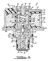
- variable force solenoid valve assembly 10 in accordance with this invention is shown in cross-section in Figures 1 and 3 and is generally designated there by reference number 10.
- Variable force solenoid valve assembly 10 is designed to be installed in an automatic transmission controller assembly having a plurality of ON/OFF solenoid valve assemblies and other related components such as is disclosed in U.S. Patent No. 4,678,006 which is hereby incorporated by reference.
- variable force solenoid valve assembly 10 receives an electrical input signal from a remote electronic controller device which would cause the variable force solenoid valve assembly 10 to controllably regulate the fluid pressure within various flow channels of an automatic transmission.
- Such pressure regulation permits finely tuned calibration of the rate and impact of gear engagement which is generated by the ON/OFF solenoid valves described in detail in the above-identified reference patent.
- FIGS 1 and 3 provide a detailed illustration of the internal working components of variable force solenoid valve assembly 10.
- the variable force solenoid valve assembly 10 has two major sub-assemblies consisting of solenoid assembly 12 and valve body assembly 14. Specifically, solenoid assembly 12 is enclosed by housing 13, having a generally closed end 15 with central bore 16 and terminal bore 18. The opposite end of housing 13 is opened and defines annular shoulder 20, such that housing 13 is slightly flared at that end. Disposed within housing 13 is a coil assembly 22 comprised of coil 23 and spool-shaped bobbin 24. Coil 23 is electrically connected to a pair of standing terminals 25 (one shown) which extend through terminal bore 18. A first flux collector 26 is positioned at one end of coil assembly 22 and forms a central threaded bore 28.
- a second flux collector 30 is provided with central bore 32. Following assembly of valve body assembly 14 to solenoid assembly 12, the lower edge of housing 13 is deflected inwardly to interlock with flux collector 30.
- Coil assembly 22 defines a central bore 34.
- Tubular insert 36 is disposed within coil assembly bore 34 and has a radially outwardly extending end 37.
- Armature assembly 38 is positioned within coil assembly bore 34 such that it can translate therein.
- Armature assembly 38 comprises a two-piece structure consisting of armature body member 40 and pin member 42. Armature body member 40 has a first opened end and a second generally closed opposite end having a central bore 41. Pin member 42 has an outer diameter which provides an interference fit with the inside diameter of central bore 41.
- armature assembly 38 The overall length of armature assembly 38 is defined prior to assembly into solenoid assembly 12 and corresponds to specific operating positions required for variable force solenoid valve assembly 10. Pin member 42 is permanently maintained within central bore 41 via an assembly staking operation. Energization of coil 28 produces an attracting force on armature assembly 38 urging it to move in an upward direction, with reference to the orientation of the elements shown in Figure 1. This action occurs through a magnetic conduction path in which magnetic fields are transferred through flux collector 26, armature assembly 38, flux collector 30 and housing 13, thereby providing a working air-gap between the first end of armature body member 40 and flux collector 26.
- Armature assembly 38 is guided to remain in a desired longitudinal orientation within bore 34 of tubular insert 36 through the guiding action provided by tubular spacer 44 and guide bearing 46, which are made of non-magnetic materials which are stable over a wide temperature range.
- Tubular spacer 44 has a radially inwardly extending surface 45 which acts to guide the upper portion of armature body member 40 and is maintained in this position through clamping engagement between tubular insert 36 and flux collector 26.
- Guide bearing 46 has a central bore 47 through which pin member 42 translates.
- Tubular spacer 44 and guide bearing 46 provide a low friction means for supporting armature assembly 38 for axial movement without employing costly precision linear ball bearings.
- Variable force solenoid valve assembly 10 includes a mechanic for providing an adjustable compliant loading onto armature assembly 38 which opposes forces imposed through energization of coil 23.
- This mechanism includes coil spring 48 disposed within central bore 50 provided in the first end of armature body member 40.
- One end of coil spring 48 rests on a lower surface 51 provided in bore 50 while the opposite end of coil spring 48 rests on spring seat 52 provided on adjustment screw 54.
- Adjustment screw 54 made from non-magnetic materials, includes a portion having a threaded external surface which threadingly engages a threaded central bore 55 provided in adjustment plug 56. Adjustment plug 56 is, in turn, threaded into threaded bore 28 of flux collector 26.
- Adjustment plug 56 is made of a magnetic material which provides means for variably adjusting the minimum working air-gap distance between armature body member 40 and flux collector 26.
- armature stop 58 is provided to make direct contact with the first end of armature body member 40. In solenoid design, it is typically necessary to control the minimum air-gap distance since the attraction force between the surfaces of an air-gap for a given current flow increases exponentially with decreased air-gap distance.
- variable force solenoid valve assembly 10 the fluid control components associated with valve body assembly 14 of variable force solenoid valve assembly 10 are shown in Figures 1 and 3.
- Variable force solenoid valve assemblies are provided in automatic transmission controller devices to enable control over fluid pressures to be provided in response to a current input signal to coil 23. Such control is achieved by selectively reducing the pressure of fluid at inlet pressure to an outlet control pressure by restricting fluid flow and through venting fluid to a transmission sump.
- damping forces include frictional, viscous, magnetic (in solenoid applications) and hydraulic forces. It is desirable to stabilize the vibrational or oscillatory characteristics of the valving which results in decay or attenuation of the amplitude of vibration with time. Attenuation of vibration amplitude is provided, according to the preferred embodiment of this invention, through the utilization of flow control components designed to be "self-balancing" so as to readily attain equilibrium conditions during operation.
- Valve body assembly 14 is primarily composed of valve body 62 and spool valve 64.
- Spool valve 64 has a central stem 65 and first, second and third lands, 66, 68 and 70 respectively, which radially extend from stem 65.
- Valve body 62 has a central bore 72 axially aligned with armature assembly 38 along a common axis.
- Valve body 62 further defines one or more radially extending passages 74 which communicate from the external surface of valve body 62 to a first chamber 76 which is exposed to fluid at inlet pressure.
- Chamber 76 is defined by the volume between first spool valve land 66 and second spool valve land 68 within valve body central bore 72.
- a second chamber 78 is defined by the volume within valve body central bore 72 below lower surface 67 of first spool valve land 66.
- a third chamber 80 is provided within valve body central bore 72 between second spool valve land 68 and third spool valve land 70.
- An annular orifice 82 is provided extending through valve body central bore 72 which fluidly communicates with first chamber 76.
- Valve body 62 further defines one or more passages 84, extending upwardly and coaxially with central bore 72, provides fluid communication between first chamber 76 at inlet pressure, orifice 82, and second chamber 78 at control pressure.
- One or more radially extending passages 86 provide fluid communication at control pressure between passage 84, third chamber 80 and outlet port 87.
- One or more radially extending exhaust passages 88 provide fluid communication between third chamber 80 and a transmission sump (not shown).
- Welsh plug 90 encloses the space at the lower end of valve body assembly 14.
- Pin member 42 of armature assembly 38 is in pressed, fitted engagement with spool valve 64 via a bore 92 provided at the upper end of third land 70. This engagement permits spool valve 64 to move in concert with armature assembly 38.
- the external peripheral surface of valve body 62 includes an annular groove 94 having seal 95 disposed therein.
- the external surface of valve body 62 further defines a radially extending shoulder 96 which is disposed within a similarly configured groove 98 provided in flux collector 30 to provide proper orientation of the components during assembly.
- Flux collector 30 defines groove 100 having seal 101 disposed therein. This arrangement provides separated fluid passages wherein inlet pressure is provided via inlet passage 74 and control pressure is provided through passages 84 and 86. Fluid can be vented from the valve body assembly 14 to an external sump through exhaust passage 88.
- variable force solenoid assembly valve 10 Utilization of a three land spool valve 64 interactive with fluid flow passages 74, 84, 86 and 88 and chambers 76, 78 and 80, as configured in valve body 62, generates positive hydraulic damping characteristics during fluid flow conditions. Positive damping promotes "self-balancing" characteristics which tend to attenuate unstable spool valve vibration or oscillation commonly realized in variable force solenoid valves employing spool valves having two lands. Three land spool valve 64, attenuates the amplitude of spool valve oscillation during changing flow conditions so as to provide a stable, controllable valve body assembly 14 during dynamic flow conditions and static equilibrium conditions.
- fluid at inlet pressure is provided through inlet passage 74 into first chamber 76.
- This fluid is permitted to flow from first chamber 76 into passage 84 through annular orifice 82 which extends through central bore 72 of valve body 62.
- First land 66 of spool valve 64 acts to restrict the flow of fluid through orifice 82 thereby defining a first flow restriction.
- Fluid in passage 84 communicates with second chamber 78 and hydraulically acts upon bottom surface 67 of first spool valve land 66.
- Passage 84 also fluidly communicates with passage 86 and with the third chamber 80.
- This fluid flow causes a resultant force to act on spool valve 64, which urges it in an upward direction to a position where the force exerted by spring 48, armature assembly 38, and the fluid pressure acting on spool valve 64 within first chamber 76, second chamber 78 and third chamber 80 are balanced.
- the pressure acting in second chamber 78 on bottom surface 67 of first spool valve land 66 is defined to be the feedback pressure which is substantially equal to the control pressure flowing through outlet port 87.
- such force balancing causes spool valve 64 to be displaced upwardly to increase the first fluid flow restriction between first spool valve land 66, orifice 82 and first chamber 76.
- This flow restriction together with a second flow restriction which permits intentional fluid leakage between third chamber 80, third spool valve land 70 and exhaust passage 88 to a sump will provide a regulated control pressure at some predetermined level, for example, 93 psi then the inlet pressure is about 140 psi.
- a given level of current through coil 23 will cause a magnetic force to be applied onto armature assembly 38 urging it in an upward direction, which is opposed by the force imposed by spring 48 and aided by the feedback pressure acting on the lower surface 67 of first land 66.
- This action has the effect of unbalancing the above described equilibrium.
- the resultant force causes armature assembly 38 and spool valve 64 to move in an upward direction and seek a new equilibrium condition.
- Such action further restricts the flow between first chamber 76, orifice 82 and passage 84, and simultaneously reduces the restriction of fluid flow between third chamber 80 and exhaust passage 88 provided by third land 70 since the extent of overlap between the bore 72 and third land 70 becomes reduced. Accordingly, controlled energization of coil 23 enables the fluid pressure of the control pressure to be variably reduced from the non-energized equilibrium control pressure in a controlled manner.
- Stable control of spool valve movement upon controlled energization of coil 23 inhibits natural self-excited oscillation, thereby reducing the time for reaching new equilibrium conditions after controlled energization of the coil 23.
- Figure 1 illustrates variable force solenoid valve assembly 10 in an energized state.
- fluid flow through chamber 76 into passage 84 is restricted from flowing through orifice 82 by the upper surface of first spool valve land 66 so as to controllably regulate the pressure of the fluid flowing through passage 84.
- Figure 3 illustrates variable force solenoid valve assembly 10 in a de-energized state.
- the flow restriction between first chamber 76 and passage 84 is reduced so as to permit fluid at a greater control pressure to flow through passage 84 to outlet port 87.
- the flow restriction between exhaust passage 88 and third spool valve land 70 is increased so as to limit the leakage flow of fluid at control pressure through exhaust passage 88 to the sump.
Abstract
Description
- This invention relates to solenoid operated fluid control devices, and more particularly to a variable force solenoid valve assembly adapted for use in an automatic transmission controller for controllably reducing a fluid inlet pressure to an outlet control pressure.
- In the past, automatic transmissions used in motor vehicles were typically controlled through fluidic control systems incorporating numerous piston and cylinder assemblies. Although such devices operate satisfactorily, they have several drawbacks including high cost attributable to the high precision necessary in machining the components and the necessity of providing and assembling numerous components. Further, such systems are restricted in their operational capabilities. Modern motor vehicles are incorporating increasing numbers of electronically controlled sub-systems and particular attention is presently being directed toward designing electronically controlled automatic transmission controllers. This invention relates specifically to an improved variable force solenoid valve assembly which can be employed in such a controller device.
- Variable force solenoid valve assemblies are used in electronic transmission controllers to provide control over fluid pressures rich are to be provided in response to an electrical input signal supplied to the solenoid. In particular, variable force solenoid valve assemblies are employed to provide regulation of the "shift-feel" of an automatic transmission. "Shift-feel" is the sudden and harsh impact felt by the vehicle operator due to engagement and disengagement of the transmission gearing upon energization of ON/OFF solenoid valves, typically provided in such electronic controllers. Such sudden and harsh shift-feel is extremely undesirable. Variable force solenoid valve assemblies permit the calibration and fine adjustment of shift-feel to provide a smoother transition during transmission gear changes.
- A number of significant design challenges are presented in designing a variable force solenoid valve assembly for controllably regulating the fluid pressure delivered to an outlet port of a transmission controller relative to the inlet line pressure. Controlled energization of the solenoid enables the control pressure to be effectively modulated. However, precise regulation of the control pressure necessitates a highly stable fluid flow condition which is directly influenced by the design of the flow control valving components and the fluid communication therethrough. Stable flow conditions tend to minimize undesirable self-excited oscillation of the valving components thereby promoting hydraulic equilibrium conditions.
- Typically, variable force solenoid devices are provided with fluid control components consisting of a spool valve having a stem and two radially extending lobes or lands. The spool valve is movably confined within a valve body to create flow restrictions for pressure regulation. Fluid passages are provided in the valve body which communicate with the various surfaces of the spool valve. Commonly, fluid at inlet pressure is delivered to a flow restriction provided between the two spool valve lands. The flow restriction enables the fluid pressure to be reduced to a desired outlet control pressure. However, the fluid forces acting on the two lands of the spool valve generate a negative hydraulic damping characteristic. Negative damping produces self-excited vibration or oscillation of the spool valve during fluid flow conditions. Such self-excited oscillation inhibits accurate regulation of the control pressure. Additionally, the self-excited oscillation of the spool valve makes the variable force solenoid valve unstable and difficult to calibrate.
- The present invention discloses an improved variable force solenoid valve assembly for regulating the outlet control pressure through utilization of valving components providing for positive fluid dumping control. Specifically, the present invention discloses flow control components associated with a solenoid valve assembly comprising a three land spool valve confined within a valve body, the combination of which generates positive fluid dumping characteristics. This positive fluid dumping has the effect of attenuating the amplitude of the natural oscillation or vibration of the spool valve generated by the flow of fluid. Such a design provides extremely stable control over spool valve oscillation which permits improved regulation of the outlet control pressure and accurate and repeatable initial calibration of the valve components.
- Another advantage of the variable force solenoid device according to this invention is its ability to be easily calibrated for the desired vehicular application.
- Yet another advantage of this invention is its ease of assembly due to the use of pre-calibrated sub-assemblies.
- The present invention permits efficient packaging through the use of variable force output solenoids. Excellent fluid flow characteristics are provided by designing the valve elements of the valve body assembly such that they provide passages and orifices designed to reduce the tendency for generation of high frequency oscillation and eddies during fluid flow through the valve.
- Additional benefits and advantages of the present invention will apparent to those skilled in the art to which this invention relates from the subsequent description of the preferred embodiments and the appended claims, taken in conjunction with the accompanying drawings.
-
- Figure 1 is a cross-sectional view through a variable force solenoid valve assembly, shown in an energized position, in accordance with the preferred embodiment of the present invention;
- Figure 2 is a pictorial view of an assembled variable force solenoid valve assembly showing electrical connections; and
- Figure 3 is an enlarged cross-sectional view through a variable force solenoid valve assembly, shown in a de-energized position, in accordance with the preferred embodiment of the present invention.
- A variable force solenoid valve assembly in accordance with this invention is shown in cross-section in Figures 1 and 3 and is generally designated there by reference number 10. Variable force solenoid valve assembly 10 is designed to be installed in an automatic transmission controller assembly having a plurality of ON/OFF solenoid valve assemblies and other related components such as is disclosed in U.S. Patent No. 4,678,006 which is hereby incorporated by reference. In operation, variable force solenoid valve assembly 10 receives an electrical input signal from a remote electronic controller device which would cause the variable force solenoid valve assembly 10 to controllably regulate the fluid pressure within various flow channels of an automatic transmission. Such pressure regulation permits finely tuned calibration of the rate and impact of gear engagement which is generated by the ON/OFF solenoid valves described in detail in the above-identified reference patent.
- Figures 1 and 3 provide a detailed illustration of the internal working components of variable force solenoid valve assembly 10. The variable force solenoid valve assembly 10 has two major sub-assemblies consisting of
solenoid assembly 12 andvalve body assembly 14. Specifically,solenoid assembly 12 is enclosed byhousing 13, having a generally closedend 15 withcentral bore 16 andterminal bore 18. The opposite end ofhousing 13 is opened and defines annular shoulder 20, such thathousing 13 is slightly flared at that end. Disposed withinhousing 13 is acoil assembly 22 comprised ofcoil 23 and spool-shaped bobbin 24.Coil 23 is electrically connected to a pair of standing terminals 25 (one shown) which extend throughterminal bore 18. A first flux collector 26 is positioned at one end ofcoil assembly 22 and forms a central threadedbore 28. At the opposite end ofcoil assembly 22, asecond flux collector 30 is provided withcentral bore 32. Following assembly ofvalve body assembly 14 tosolenoid assembly 12, the lower edge ofhousing 13 is deflected inwardly to interlock withflux collector 30.Coil assembly 22 defines a central bore 34. Tubular insert 36 is disposed within coil assembly bore 34 and has a radially outwardly extending end 37. Armature assembly 38 is positioned within coil assembly bore 34 such that it can translate therein. Armature assembly 38 comprises a two-piece structure consisting of armature body member 40 andpin member 42. Armature body member 40 has a first opened end and a second generally closed opposite end having a central bore 41.Pin member 42 has an outer diameter which provides an interference fit with the inside diameter of central bore 41. The overall length of armature assembly 38 is defined prior to assembly intosolenoid assembly 12 and corresponds to specific operating positions required for variable force solenoid valve assembly 10.Pin member 42 is permanently maintained within central bore 41 via an assembly staking operation. Energization ofcoil 28 produces an attracting force on armature assembly 38 urging it to move in an upward direction, with reference to the orientation of the elements shown in Figure 1. This action occurs through a magnetic conduction path in which magnetic fields are transferred through flux collector 26, armature assembly 38,flux collector 30 andhousing 13, thereby providing a working air-gap between the first end of armature body member 40 and flux collector 26. Armature assembly 38 is guided to remain in a desired longitudinal orientation within bore 34 of tubular insert 36 through the guiding action provided by tubular spacer 44 and guide bearing 46, which are made of non-magnetic materials which are stable over a wide temperature range. Tubular spacer 44 has a radially inwardly extendingsurface 45 which acts to guide the upper portion of armature body member 40 and is maintained in this position through clamping engagement between tubular insert 36 and flux collector 26. Guide bearing 46 has a central bore 47 through whichpin member 42 translates. Tubular spacer 44 and guide bearing 46 provide a low friction means for supporting armature assembly 38 for axial movement without employing costly precision linear ball bearings. - Variable force solenoid valve assembly 10 includes a mechanic for providing an adjustable compliant loading onto armature assembly 38 which opposes forces imposed through energization of
coil 23. This mechanism includes coil spring 48 disposed within central bore 50 provided in the first end of armature body member 40. One end of coil spring 48 rests on a lower surface 51 provided in bore 50 while the opposite end of coil spring 48 rests on spring seat 52 provided on adjustment screw 54. Adjustment screw 54, made from non-magnetic materials, includes a portion having a threaded external surface which threadingly engages a threadedcentral bore 55 provided inadjustment plug 56.Adjustment plug 56 is, in turn, threaded into threaded bore 28 of flux collector 26. By adjustably changing the positioning of adjustment screw 54, a variation in the biasing force exerted by coil spring 48 is provided by changing the amount of pre-compression of spring 48.Adjustment plug 56, on the other hand, is made of a magnetic material which provides means for variably adjusting the minimum working air-gap distance between armature body member 40 and flux collector 26. During operation of variable force valve assembly 10,armature stop 58 is provided to make direct contact with the first end of armature body member 40. In solenoid design, it is typically necessary to control the minimum air-gap distance since the attraction force between the surfaces of an air-gap for a given current flow increases exponentially with decreased air-gap distance. When separation distances extremely small, a change in state of the solenoid valve assembly following de-energization becomes less reliable if any residual magnetism is present when no electrical current is flowing through the coil. Direct contact or excessively small air-gap distances should be avoided since they can detrimentally effect the linearity characteristics of the solenoid valve assembly. - In accordance with another feature of this invention, the fluid control components associated with
valve body assembly 14 of variable force solenoid valve assembly 10 are shown in Figures 1 and 3. Variable force solenoid valve assemblies are provided in automatic transmission controller devices to enable control over fluid pressures to be provided in response to a current input signal tocoil 23. Such control is achieved by selectively reducing the pressure of fluid at inlet pressure to an outlet control pressure by restricting fluid flow and through venting fluid to a transmission sump. - In fluid control valving design, it is typically necessary to compensate for various damping forces acting upon the valving during operation which can cause vibrational instability. Such damping forces include frictional, viscous, magnetic (in solenoid applications) and hydraulic forces. It is desirable to stabilize the vibrational or oscillatory characteristics of the valving which results in decay or attenuation of the amplitude of vibration with time. Attenuation of vibration amplitude is provided, according to the preferred embodiment of this invention, through the utilization of flow control components designed to be "self-balancing" so as to readily attain equilibrium conditions during operation.
-
Valve body assembly 14 is primarily composed ofvalve body 62 and spool valve 64. Spool valve 64 has a central stem 65 and first, second and third lands, 66, 68 and 70 respectively, which radially extend from stem 65.Valve body 62 has acentral bore 72 axially aligned with armature assembly 38 along a common axis.Valve body 62 further defines one or more radially extendingpassages 74 which communicate from the external surface ofvalve body 62 to a first chamber 76 which is exposed to fluid at inlet pressure. Chamber 76 is defined by the volume between first spool valve land 66 and second spool valve land 68 within valve body central bore 72. Asecond chamber 78 is defined by the volume within valve body central bore 72 below lower surface 67 of first spool valve land 66. A third chamber 80 is provided within valve body central bore 72 between second spool valve land 68 and third spool valve land 70. Anannular orifice 82 is provided extending through valve body central bore 72 which fluidly communicates with first chamber 76.Valve body 62 further defines one ormore passages 84, extending upwardly and coaxially withcentral bore 72, provides fluid communication between first chamber 76 at inlet pressure,orifice 82, andsecond chamber 78 at control pressure. One or more radially extendingpassages 86 provide fluid communication at control pressure betweenpassage 84, third chamber 80 andoutlet port 87. One or more radially extendingexhaust passages 88 provide fluid communication between third chamber 80 and a transmission sump (not shown).Welsh plug 90 encloses the space at the lower end ofvalve body assembly 14. -
Pin member 42 of armature assembly 38 is in pressed, fitted engagement with spool valve 64 via a bore 92 provided at the upper end of third land 70. This engagement permits spool valve 64 to move in concert with armature assembly 38. The external peripheral surface ofvalve body 62 includes an annular groove 94 havingseal 95 disposed therein. The external surface ofvalve body 62 further defines a radially extending shoulder 96 which is disposed within a similarly configuredgroove 98 provided influx collector 30 to provide proper orientation of the components during assembly.Flux collector 30 definesgroove 100 havingseal 101 disposed therein. This arrangement provides separated fluid passages wherein inlet pressure is provided viainlet passage 74 and control pressure is provided throughpassages valve body assembly 14 to an external sump throughexhaust passage 88. - Operation of the variable force solenoid assembly valve 10 will now be explained with reference to Figures 1 and 3. Utilization of a three land spool valve 64 interactive with
fluid flow passages chambers 76, 78 and 80, as configured invalve body 62, generates positive hydraulic damping characteristics during fluid flow conditions. Positive damping promotes "self-balancing" characteristics which tend to attenuate unstable spool valve vibration or oscillation commonly realized in variable force solenoid valves employing spool valves having two lands. Three land spool valve 64, attenuates the amplitude of spool valve oscillation during changing flow conditions so as to provide a stable, controllablevalve body assembly 14 during dynamic flow conditions and static equilibrium conditions. Specifically, fluid at inlet pressure is provided throughinlet passage 74 into first chamber 76. This fluid is permitted to flow from first chamber 76 intopassage 84 throughannular orifice 82 which extends throughcentral bore 72 ofvalve body 62. First land 66 of spool valve 64 acts to restrict the flow of fluid throughorifice 82 thereby defining a first flow restriction. Fluid inpassage 84 communicates withsecond chamber 78 and hydraulically acts upon bottom surface 67 of first spool valve land 66.Passage 84 also fluidly communicates withpassage 86 and with the third chamber 80. This fluid flow causes a resultant force to act on spool valve 64, which urges it in an upward direction to a position where the force exerted by spring 48, armature assembly 38, and the fluid pressure acting on spool valve 64 within first chamber 76,second chamber 78 and third chamber 80 are balanced. The pressure acting insecond chamber 78 on bottom surface 67 of first spool valve land 66 is defined to be the feedback pressure which is substantially equal to the control pressure flowing throughoutlet port 87. Preferably, in the absence of current flow throughcoil 23, such force balancing causes spool valve 64 to be displaced upwardly to increase the first fluid flow restriction between first spool valve land 66,orifice 82 and first chamber 76. This flow restriction, together with a second flow restriction which permits intentional fluid leakage between third chamber 80, third spool valve land 70 andexhaust passage 88 to a sump will provide a regulated control pressure at some predetermined level, for example, 93 psi then the inlet pressure is about 140 psi. The resultant forces of the fluid acting on each of spool valve lands 66, 68 and 70 respectively, provide a stable, self-balanced spool valve which enables accurate regulation of the outlet control pressure. Controlled modulation over the control pressure is provided by selectively energizingcoil 23. A given level of current throughcoil 23 will cause a magnetic force to be applied onto armature assembly 38 urging it in an upward direction, which is opposed by the force imposed by spring 48 and aided by the feedback pressure acting on the lower surface 67 of first land 66. This action has the effect of unbalancing the above described equilibrium. The resultant force causes armature assembly 38 and spool valve 64 to move in an upward direction and seek a new equilibrium condition. Such action further restricts the flow between first chamber 76,orifice 82 andpassage 84, and simultaneously reduces the restriction of fluid flow between third chamber 80 andexhaust passage 88 provided by third land 70 since the extent of overlap between thebore 72 and third land 70 becomes reduced. Accordingly, controlled energization ofcoil 23 enables the fluid pressure of the control pressure to be variably reduced from the non-energized equilibrium control pressure in a controlled manner. - Stable control of spool valve movement upon controlled energization of
coil 23 inhibits natural self-excited oscillation, thereby reducing the time for reaching new equilibrium conditions after controlled energization of thecoil 23. - During initial assembly and calibration, fluid at inlet pressure is applied through
inlet passages 74. A non-magnetic rod (not shown) is inserted through the threaded central bore provided in adjustment plug 56 to engage coil spring 48. Coil spring 48 is compressed with the calibration rod to obtain a desired control pressure atoutlet port 87. Next, a voltage signal is applied tocoil 23 to provide a predetermined current, preferably 0.8 amps, while the coil spring 46 is maintained as compressed by the calibration rod.Adjustment plug 56 is adjustably threaded inwardly until a desired control pressure is provided atoutlet port 87 which occurs when a proper air-gap distance exists between flux collector 26 and the upper portion of armature assembly 38. The current is then removed from the assembly 10 and the calibration rod is removed so as to allow installation of adjustment screw 54. Adjustment screw 54 is adjustably threaded intoadjustment plug 56 to re-obtain the original outlet control pressure. - Figure 1 illustrates variable force solenoid valve assembly 10 in an energized state. In this condition, fluid flow through chamber 76 into
passage 84 is restricted from flowing throughorifice 82 by the upper surface of first spool valve land 66 so as to controllably regulate the pressure of the fluid flowing throughpassage 84. Figure 3 illustrates variable force solenoid valve assembly 10 in a de-energized state. The flow restriction between first chamber 76 andpassage 84 is reduced so as to permit fluid at a greater control pressure to flow throughpassage 84 tooutlet port 87. In this condition, the flow restriction betweenexhaust passage 88 and third spool valve land 70, is increased so as to limit the leakage flow of fluid at control pressure throughexhaust passage 88 to the sump. - While the above description constitutes the preferred embodiments of the present invention, it will be appreciated that the invention is acceptable to modification, variation and change without departing from the proper scope and fair meaning of the accompanying claims.
Claims (22)
a solenoid assembly (12) having a movable armature assembly (38) adapted to translate within said solenoid assembly (12) in response to said electrical input signal;
a valve body (62) defining a central bore (72) axially aligned with said armature assembly (38), said valve body (62) coupled to said solenoid assembly (12); and
valve means, disposed within said valve body central bore (72), for producing a first and second flow restriction for controllably reducing said inlet pressure to said control pressure in response to movement of said armature assembly (38), said valve means defining first, second, and third chambers (76, 78, 80) within said valve body central bore (72) such that said first chamber (76) fluidly communicates with said inlet pressure and said second and third chambers (78, 80) fluidly communicate with fluid at said control pressure, thereby providing positive damping of said valve means.
an energization coil assembly (22) defining a longitudinal bore (34), said armature assembly (38) disposed in said bore (34) and adapted to translate in response to energization of said coil assembly (22);
pole means (26, 54-56) for defining a working air-gap across which magnetic fields are transferred thereby generating an attracting force between said pole means (26, 54-56) and said armature assembly (38) which urges said armature assembly (38) to move toward said pole means (26, 54-56) when said coil assembly (22) is energized; and
spring means (48) disposed between said pole means (26, 54-56) and said armature assembly (38) urging said armature assembly (38) away from said pole means (26, 54-56) when said coil assembly (22) is de-energized.
a first chamber (76) within said valve body central bore (72) defined between said first and second spool valve lands (66, 68);
first passage means (74) for communicating fluid at inlet pressure to said first chamber (76);
a second chamber (78) within said valve body central bore (72) defined by a surface (67) of said first land (66) opposite said central stem (65) and said valve body central bore (72);
a third chamber (80) within said valve body central bore (72) defined between said second and third spool valve lands (68, 70);
second passage means (84) for communicating fluid at control pressure to said second and third chambers (78, 80);
an annular orifice (82) extending through said valve body central bore (72) providing fluid communication between said first chamber (76) and said second passage means (84), said annular orifice (82) provided in close proximity to said surface (67) of said first land (66) adjacent said central stem (65) of said spool valve (64) such that translational movement of said spool valve (64) acts to variably restrict the flow of fluid through said orifice (82) so as to define said first flow restriction;
third passage means (86) for communicating fluid at control pressure from said second passage means (84) to said third chamber (80) and an outlet port;
fourth passage means (88) for communicating fluid at control pressure within said third chamber (80) to a sump, fluid flow through said fourth passage means (88) restricted by said third land (70) of said spool valve (64) such that translational movement of said spool valve (64) variably restricts fluid flow through said fourth passage means (88) so as to define said second flow restriction; and
whereby movement of said armature assembly (38) toward said pole means (26, 54-56) upon controlled energization of said coil assembly (22) produces corresponding movement of said spool valve (64) within said valve body central bore (72) so as to decrease the flow of fluid through said first flow restriction while increasing the flow of fluid through said second flow restriction so as to decrease the regulated control pressure, and whereby, upon de-energization of said coil assembly (22) , said spring means (48) urges said armature (38) and said spool valve (64) away from said pole means (26, 54-56) so as to increase the fluid flow through said first flow restriction while decreasing the fluid flow through said second flow restriction so as to increase the regulated control pressure.
an energization coil assembly (22) defining a central bore (34);
a movable armature assembly (38) disposed in said central bore (34) and adapted to translate in said central bore (34) in response to energization of said coil assembly (22);
a first flux collector (26) magnetically coupled to said coil assembly (22) , said first flux collector (26) having adjustment means (54-56) for varying the minimum air-gap between said armature assembly (38) and said first flux collector (26) across which magnetic fields are transferred for generating an attracting force between said first flux collector (26) and said armature assembly (38), said attracting force urging said armature assembly (38) to move toward said first flux collector (26) when said coil assembly (22) is energized;
spring means (48) disposed between said adjustment means (54-56) and said armature assembly (38) urging said armature assembly (38) away from said first flux collector (26) when said coil assembly (22) is de-energized;
a second flux collector (30) having a central bore (32) and being disposed below, and adjacent to, said coil assembly (22);
a housing (13) for enclosing said first flux collector (26), said coil assembly (22), and said second flux collector (30);
a valve body (62) defining a central bore (72), said valve body (62) fixedly disposed within said central bore (32) of said second flux collector (30);
a spool valve (64) disposed within said valve body central bore (72) having a central stem (65) and first, second, and third lands (66, 68, 70) radially extending from said stem (65);
means (40-42) for coupling said spool valve (64) to said armature assembly (38) so as to permit movement of said spool valve (64) within said valve body central bore (72) in response to movement of said armature assembly (38);
a first chamber (76) within said valve body central bore (72) defined between said first and second lands (66, 68) of said spool valve (64);
a second chamber (78) defined by said valve body central bore (72) and a surface (67) of said first land (66) opposite said central stem (65);
a third chamber (80) within said valve body central bore (72) defined between said second and third lands (68, 70) of said spool valve (64);
first passage means (74) for communicating fluid at said inlet pressure to said first chamber (76);
second passage means (84) for communicating fluid at control pressure to said second chamber (78);
third passage means (86) for communicating fluid at control pressure from said second passage means (84) to said third chamber (80) and said automatic transmission;
fourth passage means (88) for communicating fluid at control pressure within said third chamber (80) to a sump;
first flow restriction means for controllably restricting the flow of fluid between said first chamber (76) and said second passage means (84) in response to movement of said armature assembly (38);
second flow restriction means for controllably restricting the flow of fluid between said third chamber (80) and said fourth passage means (88) in response to movement of said armature assembly (38); and
whereby, said control pressure is controllably regulated in response to a resultant force imposed on said spool valve (64) through the interaction of said spring means (48), the controlled energization and de-energization of said coil assembly (22) and said fluid pressure acting on said spool valve (64) within said first, second, and third chambers (76, 78, 80).
Applications Claiming Priority (2)
| Application Number | Priority Date | Filing Date | Title |
|---|---|---|---|
| US31699889A | 1989-02-28 | 1989-02-28 | |
| US316998 | 1989-02-28 |
Publications (3)
| Publication Number | Publication Date |
|---|---|
| EP0385286A2 true EP0385286A2 (en) | 1990-09-05 |
| EP0385286A3 EP0385286A3 (en) | 1991-07-03 |
| EP0385286B1 EP0385286B1 (en) | 1994-09-07 |
Family
ID=23231667
Family Applications (1)
| Application Number | Title | Priority Date | Filing Date |
|---|---|---|---|
| EP90103495A Expired - Lifetime EP0385286B1 (en) | 1989-02-28 | 1990-02-23 | Variable force solenoid pressure regulator for electronic transmission controller |
Country Status (3)
| Country | Link |
|---|---|
| EP (1) | EP0385286B1 (en) |
| CA (1) | CA2009338C (en) |
| DE (1) | DE69012169T2 (en) |
Cited By (9)
| Publication number | Priority date | Publication date | Assignee | Title |
|---|---|---|---|---|
| EP0490356A1 (en) * | 1990-12-13 | 1992-06-17 | Honeywell B.V. | Hollow adjusting screw |
| EP0532789A1 (en) * | 1991-09-20 | 1993-03-24 | HORST K. LOTZ Feuerschutzbaustoffe | Flame cutting machine with a multi-use and simple mass stream control |
| WO1994005939A1 (en) * | 1992-09-03 | 1994-03-17 | Electro Hydraulic Technology Limited | Linear motor valve |
| EP0676548A1 (en) * | 1994-03-11 | 1995-10-11 | Voac Hydraulics Boras Ab | Valve cartridge |
| EP0766030A2 (en) * | 1995-09-27 | 1997-04-02 | Smc Corporation | Direct-coupled solenoid valve |
| WO2005038322A1 (en) * | 2003-09-23 | 2005-04-28 | Robert Bosch Gmbh | Solenoid valve with a noise-reducing damping disk |
| WO2009093135A1 (en) | 2008-01-25 | 2009-07-30 | Eaton Corporation | Solenoid valve assembly |
| WO2011085764A1 (en) * | 2009-12-21 | 2011-07-21 | Robert Bosch Gmbh | Electromagnetically switchable valve for installation in an installation block |
| CN102568739A (en) * | 2010-12-20 | 2012-07-11 | 罗伯特绍控制器公司 | Solenoid for a direct acting valve having stepped guide tube |
Citations (5)
| Publication number | Priority date | Publication date | Assignee | Title |
|---|---|---|---|---|
| FR2140925A5 (en) * | 1971-06-09 | 1973-01-19 | Citroen Sa | |
| DE3402119A1 (en) * | 1984-01-23 | 1985-07-25 | Robert Bosch Gmbh, 7000 Stuttgart | Pressure regulator |
| US4744389A (en) * | 1985-10-15 | 1988-05-17 | Diesel Kiki Co., Ltd. | Pressure control device |
| US4836057A (en) * | 1985-02-19 | 1989-06-06 | Kabushiki Kaisha Komatsu Seisakusho | Method of controlling speed change clutches in a transmission |
| GB2221349A (en) * | 1986-03-24 | 1990-01-31 | Lectron Products | A solenoid assembly and fluid control valve |
-
1990
- 1990-02-05 CA CA002009338A patent/CA2009338C/en not_active Expired - Lifetime
- 1990-02-23 EP EP90103495A patent/EP0385286B1/en not_active Expired - Lifetime
- 1990-02-23 DE DE69012169T patent/DE69012169T2/en not_active Expired - Lifetime
Patent Citations (5)
| Publication number | Priority date | Publication date | Assignee | Title |
|---|---|---|---|---|
| FR2140925A5 (en) * | 1971-06-09 | 1973-01-19 | Citroen Sa | |
| DE3402119A1 (en) * | 1984-01-23 | 1985-07-25 | Robert Bosch Gmbh, 7000 Stuttgart | Pressure regulator |
| US4836057A (en) * | 1985-02-19 | 1989-06-06 | Kabushiki Kaisha Komatsu Seisakusho | Method of controlling speed change clutches in a transmission |
| US4744389A (en) * | 1985-10-15 | 1988-05-17 | Diesel Kiki Co., Ltd. | Pressure control device |
| GB2221349A (en) * | 1986-03-24 | 1990-01-31 | Lectron Products | A solenoid assembly and fluid control valve |
Cited By (16)
| Publication number | Priority date | Publication date | Assignee | Title |
|---|---|---|---|---|
| EP0490356A1 (en) * | 1990-12-13 | 1992-06-17 | Honeywell B.V. | Hollow adjusting screw |
| EP0532789A1 (en) * | 1991-09-20 | 1993-03-24 | HORST K. LOTZ Feuerschutzbaustoffe | Flame cutting machine with a multi-use and simple mass stream control |
| WO1994005939A1 (en) * | 1992-09-03 | 1994-03-17 | Electro Hydraulic Technology Limited | Linear motor valve |
| EP0676548A1 (en) * | 1994-03-11 | 1995-10-11 | Voac Hydraulics Boras Ab | Valve cartridge |
| US5651387A (en) * | 1994-03-11 | 1997-07-29 | Voac Hydraulics Boras Ab | Valve cartridge |
| EP0766030A2 (en) * | 1995-09-27 | 1997-04-02 | Smc Corporation | Direct-coupled solenoid valve |
| EP0766030A3 (en) * | 1995-09-27 | 1997-05-07 | Smc Corp | |
| US5785299A (en) * | 1995-09-27 | 1998-07-28 | Smc Corporation | Direct-coupled solenoid valves |
| WO2005038322A1 (en) * | 2003-09-23 | 2005-04-28 | Robert Bosch Gmbh | Solenoid valve with a noise-reducing damping disk |
| US7543795B2 (en) | 2003-09-23 | 2009-06-09 | Robert Bosch Gmbh | Solenoid valve having a noise-reducing damping disk |
| WO2009093135A1 (en) | 2008-01-25 | 2009-07-30 | Eaton Corporation | Solenoid valve assembly |
| US8082953B2 (en) | 2008-01-25 | 2011-12-27 | Eaton Corporation | Solenoid valve assembly |
| WO2011085764A1 (en) * | 2009-12-21 | 2011-07-21 | Robert Bosch Gmbh | Electromagnetically switchable valve for installation in an installation block |
| CN102753871A (en) * | 2009-12-21 | 2012-10-24 | 罗伯特·博世有限公司 | Electromagnetically switchable valve for installation in an installation block |
| CN102753871B (en) * | 2009-12-21 | 2015-11-25 | 罗伯特·博世有限公司 | For be arranged in mounting blocks can electromagnetism switch valve |
| CN102568739A (en) * | 2010-12-20 | 2012-07-11 | 罗伯特绍控制器公司 | Solenoid for a direct acting valve having stepped guide tube |
Also Published As
| Publication number | Publication date |
|---|---|
| DE69012169T2 (en) | 1995-02-02 |
| CA2009338A1 (en) | 1990-08-31 |
| CA2009338C (en) | 1995-08-01 |
| EP0385286B1 (en) | 1994-09-07 |
| DE69012169D1 (en) | 1994-10-13 |
| EP0385286A3 (en) | 1991-07-03 |
Similar Documents
| Publication | Publication Date | Title |
|---|---|---|
| US4947893A (en) | Variable force solenoid pressure regulator for electronic transmission controller | |
| US5513673A (en) | Electrically modulated pressure regulator valve with variable force solenoid | |
| US5051631A (en) | Electromagnetic solenoid valve with variable force motor | |
| US5513832A (en) | Variable force solenoid valve | |
| US6029703A (en) | Pressure solenoid control valve with flux shunt | |
| EP0565292B1 (en) | Proportional solenoid controlled valve | |
| US6435213B2 (en) | Solenoid operated hydraulic control valve | |
| US4741364A (en) | Pilot-operated valve with load pressure feedback | |
| US5509439A (en) | Electromagnetically controlled operating device in particular for valves and electrohydraulic applications | |
| US4669504A (en) | Closed loop type proportional electromagnetic valve for hydraulic control | |
| US7192005B2 (en) | Control method and controller for a solenoid-operated electrohydraulic control valve | |
| US6899313B2 (en) | Magnetic actuator and method | |
| US6343621B1 (en) | Variable force solenoid control valve | |
| WO2010088108A2 (en) | Open end variable bleed solenoid (vbs) valve with inherent viscous dampening | |
| EP0385286B1 (en) | Variable force solenoid pressure regulator for electronic transmission controller | |
| EP1755015A2 (en) | Relief valve | |
| KR100476246B1 (en) | Proportional pressure control valve | |
| EP0254483B1 (en) | Solenoid-operated fluid pressure regulator valves | |
| US7229063B2 (en) | Pressure control valve | |
| EP0160120A1 (en) | Solenoid valve | |
| EP1239356A1 (en) | Solenoid operated valve with hydraulic dampening | |
| JP2001012638A (en) | Electromechanical type variable force solenoid valve for controlling hydraulic pressure | |
| JPH0488278A (en) | Proportional flow control valve | |
| JPH0333577A (en) | Electrostrictive element type pressure control valve |
Legal Events
| Date | Code | Title | Description |
|---|---|---|---|
| PUAI | Public reference made under article 153(3) epc to a published international application that has entered the european phase |
Free format text: ORIGINAL CODE: 0009012 |
|
| AK | Designated contracting states |
Kind code of ref document: A2 Designated state(s): DE FR GB IT |
|
| PUAL | Search report despatched |
Free format text: ORIGINAL CODE: 0009013 |
|
| RHK1 | Main classification (correction) |
Ipc: F16H 61/06 |
|
| AK | Designated contracting states |
Kind code of ref document: A3 Designated state(s): DE FR GB IT |
|
| 17P | Request for examination filed |
Effective date: 19910809 |
|
| 17Q | First examination report despatched |
Effective date: 19930401 |
|
| GRAA | (expected) grant |
Free format text: ORIGINAL CODE: 0009210 |
|
| AK | Designated contracting states |
Kind code of ref document: B1 Designated state(s): DE FR GB IT |
|
| REF | Corresponds to: |
Ref document number: 69012169 Country of ref document: DE Date of ref document: 19941013 |
|
| ET | Fr: translation filed | ||
| ITF | It: translation for a ep patent filed |
Owner name: BUGNION S.P.A. |
|
| PLBE | No opposition filed within time limit |
Free format text: ORIGINAL CODE: 0009261 |
|
| STAA | Information on the status of an ep patent application or granted ep patent |
Free format text: STATUS: NO OPPOSITION FILED WITHIN TIME LIMIT |
|
| 26N | No opposition filed | ||
| REG | Reference to a national code |
Ref country code: GB Ref legal event code: IF02 |
|
| PGFP | Annual fee paid to national office [announced via postgrant information from national office to epo] |
Ref country code: DE Payment date: 20090227 Year of fee payment: 20 |
|
| PGFP | Annual fee paid to national office [announced via postgrant information from national office to epo] |
Ref country code: GB Payment date: 20090106 Year of fee payment: 20 |
|
| PGFP | Annual fee paid to national office [announced via postgrant information from national office to epo] |
Ref country code: IT Payment date: 20090213 Year of fee payment: 20 |
|
| PGFP | Annual fee paid to national office [announced via postgrant information from national office to epo] |
Ref country code: FR Payment date: 20090206 Year of fee payment: 20 |
|
| REG | Reference to a national code |
Ref country code: GB Ref legal event code: PE20 Expiry date: 20100222 |
|
| PG25 | Lapsed in a contracting state [announced via postgrant information from national office to epo] |
Ref country code: GB Free format text: LAPSE BECAUSE OF EXPIRATION OF PROTECTION Effective date: 20100222 |
|
| PG25 | Lapsed in a contracting state [announced via postgrant information from national office to epo] |
Ref country code: DE Free format text: LAPSE BECAUSE OF EXPIRATION OF PROTECTION Effective date: 20100223 |