EP0765976A2 - Lippenventil - Google Patents
Lippenventil Download PDFInfo
- Publication number
- EP0765976A2 EP0765976A2 EP96119349A EP96119349A EP0765976A2 EP 0765976 A2 EP0765976 A2 EP 0765976A2 EP 96119349 A EP96119349 A EP 96119349A EP 96119349 A EP96119349 A EP 96119349A EP 0765976 A2 EP0765976 A2 EP 0765976A2
- Authority
- EP
- European Patent Office
- Prior art keywords
- tank
- valve
- inlet
- vacuum
- pump
- Prior art date
- Legal status (The legal status is an assumption and is not a legal conclusion. Google has not performed a legal analysis and makes no representation as to the accuracy of the status listed.)
- Ceased
Links
- 238000007789 sealing Methods 0.000 claims abstract description 13
- 239000013536 elastomeric material Substances 0.000 claims abstract description 7
- HQQADJVZYDDRJT-UHFFFAOYSA-N ethene;prop-1-ene Chemical group C=C.CC=C HQQADJVZYDDRJT-UHFFFAOYSA-N 0.000 claims description 4
- 239000002699 waste material Substances 0.000 description 33
- XLYOFNOQVPJJNP-UHFFFAOYSA-N water Substances O XLYOFNOQVPJJNP-UHFFFAOYSA-N 0.000 description 28
- 239000013505 freshwater Substances 0.000 description 12
- 238000010276 construction Methods 0.000 description 7
- 238000011010 flushing procedure Methods 0.000 description 4
- 239000007788 liquid Substances 0.000 description 4
- 239000004033 plastic Substances 0.000 description 4
- 239000004743 Polypropylene Substances 0.000 description 3
- -1 polypropylene Polymers 0.000 description 3
- 229920001155 polypropylene Polymers 0.000 description 3
- 238000005086 pumping Methods 0.000 description 3
- 230000000712 assembly Effects 0.000 description 2
- 238000000429 assembly Methods 0.000 description 2
- 238000001746 injection moulding Methods 0.000 description 2
- 230000002879 macerating effect Effects 0.000 description 2
- 239000000463 material Substances 0.000 description 2
- 239000007787 solid Substances 0.000 description 2
- 239000011343 solid material Substances 0.000 description 2
- 241000405070 Percophidae Species 0.000 description 1
- 238000000071 blow moulding Methods 0.000 description 1
- 239000000919 ceramic Substances 0.000 description 1
- 238000006073 displacement reaction Methods 0.000 description 1
- 230000005611 electricity Effects 0.000 description 1
- 238000005516 engineering process Methods 0.000 description 1
- 230000005484 gravity Effects 0.000 description 1
- 238000007689 inspection Methods 0.000 description 1
- 230000007257 malfunction Effects 0.000 description 1
- 238000004519 manufacturing process Methods 0.000 description 1
- QSHDDOUJBYECFT-UHFFFAOYSA-N mercury Chemical compound [Hg] QSHDDOUJBYECFT-UHFFFAOYSA-N 0.000 description 1
- 229910052753 mercury Inorganic materials 0.000 description 1
- 239000000203 mixture Substances 0.000 description 1
- 230000004048 modification Effects 0.000 description 1
- 238000012986 modification Methods 0.000 description 1
- 238000010106 rotational casting Methods 0.000 description 1
- 239000010865 sewage Substances 0.000 description 1
- 239000008400 supply water Substances 0.000 description 1
Images


Classifications
-
- E—FIXED CONSTRUCTIONS
- E03—WATER SUPPLY; SEWERAGE
- E03D—WATER-CLOSETS OR URINALS WITH FLUSHING DEVICES; FLUSHING VALVES THEREFOR
- E03D5/00—Special constructions of flushing devices, e.g. closed flushing system
-
- B—PERFORMING OPERATIONS; TRANSPORTING
- B60—VEHICLES IN GENERAL
- B60R—VEHICLES, VEHICLE FITTINGS, OR VEHICLE PARTS, NOT OTHERWISE PROVIDED FOR
- B60R15/00—Arrangements or adaptations of sanitation devices
- B60R15/04—Toilet facilities
-
- B—PERFORMING OPERATIONS; TRANSPORTING
- B63—SHIPS OR OTHER WATERBORNE VESSELS; RELATED EQUIPMENT
- B63B—SHIPS OR OTHER WATERBORNE VESSELS; EQUIPMENT FOR SHIPPING
- B63B29/00—Accommodation for crew or passengers not otherwise provided for
- B63B29/02—Cabins or other living spaces; Construction or arrangement thereof
- B63B29/14—Closet or like flushing arrangements; Washing or bathing facilities peculiar to ships
-
- B—PERFORMING OPERATIONS; TRANSPORTING
- B63—SHIPS OR OTHER WATERBORNE VESSELS; RELATED EQUIPMENT
- B63B—SHIPS OR OTHER WATERBORNE VESSELS; EQUIPMENT FOR SHIPPING
- B63B29/00—Accommodation for crew or passengers not otherwise provided for
- B63B29/16—Soil water discharges
-
- E—FIXED CONSTRUCTIONS
- E03—WATER SUPPLY; SEWERAGE
- E03F—SEWERS; CESSPOOLS
- E03F1/00—Methods, systems, or installations for draining-off sewage or storm water
- E03F1/006—Pneumatic sewage disposal systems; accessories specially adapted therefore
-
- F—MECHANICAL ENGINEERING; LIGHTING; HEATING; WEAPONS; BLASTING
- F16—ENGINEERING ELEMENTS AND UNITS; GENERAL MEASURES FOR PRODUCING AND MAINTAINING EFFECTIVE FUNCTIONING OF MACHINES OR INSTALLATIONS; THERMAL INSULATION IN GENERAL
- F16K—VALVES; TAPS; COCKS; ACTUATING-FLOATS; DEVICES FOR VENTING OR AERATING
- F16K15/00—Check valves
- F16K15/14—Check valves with flexible valve members
- F16K15/144—Check valves with flexible valve members the closure elements being fixed along all or a part of their periphery
- F16K15/147—Check valves with flexible valve members the closure elements being fixed along all or a part of their periphery the closure elements having specially formed slits or being of an elongated easily collapsible form
-
- Y—GENERAL TAGGING OF NEW TECHNOLOGICAL DEVELOPMENTS; GENERAL TAGGING OF CROSS-SECTIONAL TECHNOLOGIES SPANNING OVER SEVERAL SECTIONS OF THE IPC; TECHNICAL SUBJECTS COVERED BY FORMER USPC CROSS-REFERENCE ART COLLECTIONS [XRACs] AND DIGESTS
- Y10—TECHNICAL SUBJECTS COVERED BY FORMER USPC
- Y10T—TECHNICAL SUBJECTS COVERED BY FORMER US CLASSIFICATION
- Y10T137/00—Fluid handling
- Y10T137/2931—Diverse fluid containing pressure systems
- Y10T137/3109—Liquid filling by evacuating container
-
- Y—GENERAL TAGGING OF NEW TECHNOLOGICAL DEVELOPMENTS; GENERAL TAGGING OF CROSS-SECTIONAL TECHNOLOGIES SPANNING OVER SEVERAL SECTIONS OF THE IPC; TECHNICAL SUBJECTS COVERED BY FORMER USPC CROSS-REFERENCE ART COLLECTIONS [XRACs] AND DIGESTS
- Y10—TECHNICAL SUBJECTS COVERED BY FORMER USPC
- Y10T—TECHNICAL SUBJECTS COVERED BY FORMER US CLASSIFICATION
- Y10T137/00—Fluid handling
- Y10T137/7722—Line condition change responsive valves
- Y10T137/7837—Direct response valves [i.e., check valve type]
- Y10T137/7879—Resilient material valve
- Y10T137/788—Having expansible port
- Y10T137/7882—Having exit lip
- Y10T137/7885—Multiple slit
-
- Y—GENERAL TAGGING OF NEW TECHNOLOGICAL DEVELOPMENTS; GENERAL TAGGING OF CROSS-SECTIONAL TECHNOLOGIES SPANNING OVER SEVERAL SECTIONS OF THE IPC; TECHNICAL SUBJECTS COVERED BY FORMER USPC CROSS-REFERENCE ART COLLECTIONS [XRACs] AND DIGESTS
- Y10—TECHNICAL SUBJECTS COVERED BY FORMER USPC
- Y10T—TECHNICAL SUBJECTS COVERED BY FORMER US CLASSIFICATION
- Y10T137/00—Fluid handling
- Y10T137/7722—Line condition change responsive valves
- Y10T137/7837—Direct response valves [i.e., check valve type]
- Y10T137/7879—Resilient material valve
- Y10T137/7888—With valve member flexing about securement
Definitions
- the present invention refers to a duckbill valve having an integral body of elastomeric material having a tubular inlet portion at a first end with a diameter of less than 2 inches, and side walls tapering down to sealing edges at a second end opposite the first end, the side walls and sealing edges having predetermined thicknesses.
- the invention also refers to a vacuum pump having an inlet and an outlet, and a check valve disposed in at least one of said inlet and outlet.
- Portable toilets are the most commonly used type of toilet in recreational vehicles and boats because of the minimum amount of space they require. However despite the better space utilization conventional portable toilet assemblies provide, they take up too much space for small vehicles and boats.
- a vacuum toilet assembly which takes up a minimum of space so that it can fit in vehicles and boats where vacuum toilets were previously impractical, and an assembly which also provides minimum water usage.
- the toilet itself has a width of between 14 and 15 inches, a length of 18 to 20 inches, and a height of 11 to 16 inches.
- the ball valve for connecting the vacuum tank to the toilet during flushing is less than 2.5 inches in diameter (e. g. 2 inches) rather than the conventional 3 inches.
- the waste tank is also relatively small in size, e. g. 5 gallons, and may have a dip tube and vent which allow -- in combination with the particular connection of the vacuum pump thereto -- the tank to be readily pumped out, and to allow discharge from the tank if the tank is full.
- the plastic vacuum tank also is provided in a low volume configuration since it has flat sides, and is mounted directly to and nested with the vacuum pump, the flat sides having a wall thickness to deflection ratio which allows a non-cylindrical construction of the vacuum tank.
- the particular connection of the vacuum pump with respect to the vacuum tank and waste tank avoids conventional macerating pumps (which consume electricity at such a rate as to make them impractical for small boats or RV spaces), eliminates the need for a large waste tank by using vacuum to convey waste directly into the tank, and the chances of clogs at the outlet from the vacuum tank are minimized.
- duckbill check valves provided on opposite sides of the vacuum pump (having a particular wall thickness to sealing lip ratio) maximizes functionality of the pump.
- a vacuum toilet assembly which takes up a minimum of space yet has maximum operability, minimum water usage, and minimum chance of components clogging.
- the assembly comprises the following elements: A vacuum toilet having a waste discharge normally closed by a vacuum-tight valve. A manual actuator for the vacuum tight valve.
- a fresh water tank A vacuum tank having an inlet and an outlet.
- a vacuum pump having an inlet and an outlet.
- a waste tank having an inlet.
- a first hose for connecting the waste discharge of the toilet, adjacent the vacuum-tight valve, to the vacuum tank inlet.
- Direct connection means for connecting the vacuum tank outlet directly to the vacuum pump inlet.
- a second hose for connecting the vacuum pump outlet to the waste tank inlet; and a conduit for connecting the fresh water tank to the vacuum toilet.
- the direct connection means preferably comprises a vacuum tight tubular connector in sealed relationship with an opening in the vacuum tank, which opening comprises the vacuum tank outlet; a tubular fitting integral with the vacuum pump removably connected to the vacuum tight tubular connector; and first and second check valves within or between the vacuum tight tubular connector and the integral tubular fitting.
- At least one of the first and second check valves comprises a duckbill valve of maximum diameter of less than two inches, of elastomeric material (e. g. ethylene propylene) having side walls terminating in edges, with a generally “lipless” construction; and wherein the ratio of the thickness of the side walls to the edge is approximately 1:1.
- a third duckbill valve is also preferably provided between the vacuum pump outlet and the second hose also having this size and ratio.
- the assembly also comprises a water pump for pumping water from the fresh water tank to the conduit, particularly a submersible centrifugal pump disposed within the fresh water tank.
- a water pump for pumping water from the fresh water tank to the conduit, particularly a submersible centrifugal pump disposed within the fresh water tank.
- the fresh water tank is located above the toilet, and has a cap releasably closing an opening therein; and the water pump is mounted to the cap and removable from the fresh water tank through the opening, and further comprising anti-siphon means associated with the water reservoir or conduit.
- the anti-siphon means comprises a small vent opening in the cap, and a small vent opening in the conduit between the pump and the cap within the fresh water tank.
- the water pump is preferably electrically operated, and the assembly further comprises an electrical switch controlled by operation of the handle for starting the water pump just before the handle moves the vacuum tight valve to an open position connecting the vacuum tank to the toilet discharge.
- the vacuum pump is also preferably electrically operated, and a swivel connection between the second hose and the waste tank includes electrical contacts which disconnect the vacuum pump from a source of electrical energy when the swivel connection is moved to an electrical disconnect position with respect to the waste tank.
- the waste tank, vacuum tank with vacuum pump, and fresh water tank are preferably stacked one above the other in order in a vertical stack, with the waste tank on the bottom and fresh water tank on top, the vacuum tank inlet and outlet and vacuum pump being at the bottom of the vacuum tank.
- a second fresh water tank may also be provided, stacked above the fresh water tank, with a liquid tight vertical passage between them.
- the waste tank has a bottom and a top, and a dip tube provided within the waste tank extends from adjacent the bottom to the top.
- the dip tube comprises a circular cross-section tube having a straight portion adjacent the top thereof, and a dog leg portion between the straight portion and bottom thereof, and terminated adjacent the waste tank bottom on the dog leg by a surface substantially perpendicular to the straight portion, so that the bottom opening of the dip tube is larger in area than the cross-sectional area of the circular tube, and is substantially oval in shape.
- the waste tank preferably has flat walls yet is cost-effectively made out of plastic material, particularly high density polypropylene about one-quarter inch thick. It is possible to make such a tank having no visible deflection at a vacuum of about 25 inches of mercury as long as there is no more than 80 square inches of continuous flat surface forming a wall (i. e. not interrupted by an angle or the like).
- the waste tank may be rotocast or blow molded, having a one piece construction, and avoiding the costs associated with injection molding.
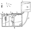
- a vacuum assembly according to the present invention is shown generally by reference numeral 10 in FIGURE 1, comprising as the main components a vacuum toilet 11 with a manual valve actuator including a handle 12 for "flushing" the toilet 11, a waste tank 13, a vacuum tank 14, a vacuum pump 15, and at least a first water tank 16 (and preferably a second water tank 17).
- the components illustrated in FIGURE 1 have a low volume configuration, the elements 13-17 being provided in a vertical stack, and taking up such a small amount of space that they fit within the hanging locker or closet 18 of the type often provided in small size recreational vehicles or boats.
- the toilet 11 itself is dimensioned so that it fits into a space normally provided for a small portable toilet, such as a SANIPOTTIE sold by SeaLand Technology, Inc. of Big Prairie, Ohio.
- the optimum space is one 14.5 inches wide, 19 inches in length (front to back), and a height of 12 inches.
- the range of dimensions are preferably 14-15 inches, 18-20 inches, and 11-16 inches, respectively.
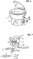
- the toilet 11 is basically of the type such as shown in U. S. Patent 4,819,279, the disclosure of which is incorporated by reference herein, including having the area where the valve hemisphere initially "cracks open" located directly above the orifice, as seen in FIG. 6 of that patent.
- the invention also has a discharge 19 (see FIG.
- a vacuum-tight valve such as the ball valve 21 (which may be spherical, as shown in the drawings, or hemispherical as shown in said patent 4,819,279).
- the ball valve 21 is conventional except that it has a diameter of less than 2.5 inches (e. g. 2 inches), rather than the conventional size of 3 inches.
- the actuator 12 (see FIG. 7) preferably is biased by a spring, e. g. torsion spring 22, to move it to a position in which the ball 21 is closed.
- the cam 24 and switch 25 are positioned with respect to each other so that the switch 25 is actuated before the valve 21 opens, the switch 25 controlling operation of a water pump 26, as will be hereinafter described.
- the toilet 11 may be mounted on a base 27 which is distinct from the ceramic toilet 11, the vacuum line 20 coming from the rear of the toilet 11/base 27 in the embodiment illustrated in FIG. 6, but the line 20 may come out from the left, right, or bottom of the base 27 instead.
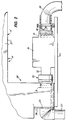
- the vacuum pump 15 and vacuum tank 14 are illustrated in more detail in FIGURES 2 and 3, with the connection between the pump 15 and tank 14 shown exploded in FIG. 4, and the connection between the flexible hose 28 between the pump 15 and the waste tank 13 at the tank 13 illustrated in FIG. 5.
- the pump 15 is preferably a self-priming positive displacement bellows pump, such as shown in U. S. Patents 3,774,461, 3,597,517, 3,529,908 and 3,382,812, which is activated by a conventional pressure differential switch (not shown in FIG. 2, but shown schematically at 51 in FIG. 7)) just inside the tank 14, as is conventional in SeaLand vacuum toilets.
- the pressure differential switch is located right with the vacuum pump and tank, in an integral module, the pump 15 and tank 13 being visible as an integral module in FIGURES 1 and 2.
- the vacuum line 20 from the toilet 11 to the tank 14 is connected to the inlet to the tank 14, while the tubular connector 30 fits within the outlet 31 from the tank 14, the connector 30 in turn connected to the integral fitting 32 of the pump 15.
- the connector 30 may have an O-ring 33 which makes a sealing fit with the opening 31, and an internally threaded termination 34 may be provided on the fitting 32 to releasably connect to connector 30, engaging the external threads 35 thereof.
- the vacuum tank 14 is also particularly configured for low volume configuration.
- the vacuum the tank 14 will "hold” is relatively large, it is made with flat walls 37, and a bottom extension 38 also having flat walls 39, and is made of plastic.
- tank 14 can be made by rotational casting or blow molding so that it is made as one piece, and therefore the tooling costs and assembly costs of injection molding are avoided.
- the tank 14 preferably is made of high density polypropylene plastic about one quarter inch thick.
- the tank 14 with flat walls is possible because according to the invention it has been recognized that if the amount of any continuous (uninterrupted) flat surface is kept at 80 square inches or less in area there will be no visible deflection of a one quarter inch wall thickness high density polypropylene tank.
- the tank 14 illustrated in FIGURES 2 and 3 has no single flat surface of more than 80 square inches in area.
- the tank 14 typically has a nominal 2.5 gallon volume, which is sufficient to provide enough vacuum for flushing, but minimizes (especially with the flat wall, generally parallelepiped construction thereof) the volume it takes up.
- another duckbill valve 40 is provided to prevent backup of waste from hose 28 into the pump 15.
- another duckbill valve 40 is provided at the outlet 41 of the pump 15.
- the valves 36, 40 used in the practice of the invention are not conventional duckbill valves, however, but rather are improved compared to the prior art.
- the duckbill valves 36, 40 are of elastomeric material (e. g. ethylene propylene with a Type A durometer of about 40-70, e. g. 65), have a tubular inlet 42 at one end thereof of diameter of less than about 2 inches, and tapered side walls 44 between the tubular inlet 42 and edge terminations 43 of the side walls 44.
- the side walls 44 have a particular wall thickness 45, and the edges 43, where sealing takes place, also have a particular thickness.
- the ratio of the wall thickness 45 to the thickness of the sealing edges 43 is critical for optimum functionality; that is the ratio should be roughly about 1:1.
- the valve 36 (with the inlet 42 having a diameter of about 1.6 inches) functions well with a wall thickness 45 of .095 inches.
- valve 36 has generally a "lipless" construction.
- Conventional duckbill valves used to valve pure liquids typically have wide lips at the ends of the side walls, but for valving liquids with a large amount of solids - - like sewage -- the lips should have a small or zero width.
- Duckbill valves having lips with a small or zero width are "lipless” as that term is conventionally used, and used herein.
- the valves 36, 40 according to the invention are thus lipless.
- FIGURE 5 shows a swivel connector 46 that is provided according to the present invention to connect the flexible pipe 28 which leads from the pump 15 to the waste tank 13.
- the swivel connector 46 is provided with electrical contacts 47 which cooperate with electrical contacts 48 that are stationary with respect to the tank 13 so that when the connector 46 is rotated to a particular position with respect to tank 13, which position allows it to be disconnected from tank 13, the contacts 47, 48 are not in engagement (as they usually are), breaking a circuit flowing between them and thereby cutting the pump 15 off from the battery 50 (see FIG. 7), or other source of emf, so that the electrical pump can not operate.
- the pump 15 is normally controlled by operation of the conventional pressure differential switch 51.
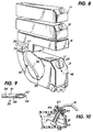
- FIGURE 8 shows in perspective stacking of the various tanks in the assembly 10 according to the invention, and also shows details of the tank 13, which typically has a holding volume of about 5 gallons, and may be mounted on wheels 53 for ease of transport. It also has a conventional vent valve 54, and optionally has a suction dip tube shown generally at 55, which can be connected to a pump out station, or in emergency situations when the tank 13 is in a boat and full can be used to discharge the waste directly overboard.
- the dip tube 55 has an unusual, advantageous construction. It is substantially circular in cross-section, with an outlet portion 56 at one end thereof, a substantially vertical straight portion 57, and a dog leg portion 58. The dog leg portion terminates at end 59, just above the bottom 60 of the tank 13.
- the tube In conventional holding tanks with suction dip tubes, the tube is of the same circular cross-section and cross-sectional area at the bottom thereof as during the rest of its length. It has been found according to the invention that this results in too fast a flow up the dip tube when pumping out the tank 13, and can cause toilet tissue, or other material, to clog the bottom of the tube, thereby preventing pump-out.
- the dip tube 55 is configured at the bottom 59 thereof in such a way, however, to minimize the possibility of clogging.
- the end 59 is provided in a plane substantially perpendicular to straight portion 57 of the tube 55 so that the end 59 has an opening 60 (see FIG. 9) that is generally oval-shaped, and has a larger cross-sectional area than the rest of the tube 55, as readily seen in FIG. 9.
- This particular shape of the opening 60 at the end 59 causes the tissue and other solid material to move more slowly into the tube 55, in a manner less likely to cause solid material to clog the opening (60) at the bottom of the tube 55.
- FIGURE 10 illustrates the preferred manner of mounting a water pump 26 according to the invention to supply water to the toilet 11, through conduit 61, when the tank 16 is remote from the toilet 11.
- the pump 26 is preferably a small submersible D. C. pump having a height of about 3 inches, and only about 1.5 inches in diameter. It is a centrifugal, impeller, pump having a capacity of pumping only about 2 gallons per minute, such as available from Comet-Pumpen of Kriftel, Germany, and sold under the trademark THE ELEGANT.
- the pump 26 is mounted directly to the cap 63 closing off the spout 64 of the tank 16, as by rods 65, and the pump 26 is centered with respect to the spout 64 and of small enough size so that it can be withdrawn from the tank 16 merely by unscrewing the cap 63 and pulling out away from the tank 16.
- the anti-siphon means may be very simple, comprising a small (e.g. 1/16 inch in diameter) hole 67 in cap 63, and another small hole 68 in conduit 61 within the tank 16.
- FIG. 1 Where two fresh water tanks 16, 17 are utilized, as seen in FIG. 1, it is not desirable to have to switch from one tank to the other manually after one has been exhausted; however it may still be desirable to have two different tanks 16, 17 rather than a single large one, to provide a modular arrangement.
- This is accomplished according to the invention is provided by providing an opening 70 in the top of tank 16 which is adapted to receive in liquid-tight relationship the tube 71 which extends from the bottom of the top tank 17.
- the tube 71 may have external screw threads 72 at the top thereof adapted to receive an inner cap (not shown), which may be accessed through the larger capped opening 73.
- a low volume configuration vacuum toilet assembly which uses a minimum of water, may be easily stowed, and has minimum chance of clogging or malfunction.
- FIGURE 11 where the toilet 11 is shown mounted beneath a conventional seat cushion 75 in the hull of a small boat.
- the tank 13 may have a conventional 3/4 full indicator, the water tanks may have empty indicators, etc.
Landscapes
- Engineering & Computer Science (AREA)
- Mechanical Engineering (AREA)
- Hydrology & Water Resources (AREA)
- Life Sciences & Earth Sciences (AREA)
- Public Health (AREA)
- Health & Medical Sciences (AREA)
- Combustion & Propulsion (AREA)
- Water Supply & Treatment (AREA)
- Ocean & Marine Engineering (AREA)
- Chemical & Material Sciences (AREA)
- Environmental & Geological Engineering (AREA)
- Epidemiology (AREA)
- Aviation & Aerospace Engineering (AREA)
- General Health & Medical Sciences (AREA)
- General Engineering & Computer Science (AREA)
- Sanitary Device For Flush Toilet (AREA)
- Non-Flushing Toilets (AREA)
- Vehicle Waterproofing, Decoration, And Sanitation Devices (AREA)
- Check Valves (AREA)
Applications Claiming Priority (3)
| Application Number | Priority Date | Filing Date | Title |
|---|---|---|---|
| US08/123,846 US5408704A (en) | 1993-09-09 | 1993-09-09 | Low volume vacuum toilet assembly |
| US123846 | 1993-09-09 | ||
| EP94114130A EP0643176B1 (de) | 1993-09-09 | 1994-09-08 | Raumsparende Vakuumtoilettenanordnung |
Related Parent Applications (2)
| Application Number | Title | Priority Date | Filing Date |
|---|---|---|---|
| EP94114130.1 Division | 1994-09-08 | ||
| EP94114130A Division EP0643176B1 (de) | 1993-09-09 | 1994-09-08 | Raumsparende Vakuumtoilettenanordnung |
Publications (2)
| Publication Number | Publication Date |
|---|---|
| EP0765976A2 true EP0765976A2 (de) | 1997-04-02 |
| EP0765976A3 EP0765976A3 (de) | 1998-03-25 |
Family
ID=22411241
Family Applications (2)
| Application Number | Title | Priority Date | Filing Date |
|---|---|---|---|
| EP96119349A Ceased EP0765976A3 (de) | 1993-09-09 | 1994-09-08 | Lippenventil |
| EP94114130A Expired - Lifetime EP0643176B1 (de) | 1993-09-09 | 1994-09-08 | Raumsparende Vakuumtoilettenanordnung |
Family Applications After (1)
| Application Number | Title | Priority Date | Filing Date |
|---|---|---|---|
| EP94114130A Expired - Lifetime EP0643176B1 (de) | 1993-09-09 | 1994-09-08 | Raumsparende Vakuumtoilettenanordnung |
Country Status (4)
| Country | Link |
|---|---|
| US (3) | US5408704A (de) |
| EP (2) | EP0765976A3 (de) |
| AU (1) | AU673943B2 (de) |
| DE (2) | DE643176T1 (de) |
Cited By (2)
| Publication number | Priority date | Publication date | Assignee | Title |
|---|---|---|---|---|
| EP1120501A2 (de) * | 2000-01-14 | 2001-08-01 | Sanivac Vakuumtechnik Gmbh | Zwischenbehälter für Vakuumtoilette |
| WO2020178777A1 (en) * | 2019-03-05 | 2020-09-10 | Bettiol S.r.l. | Valve device |
Families Citing this family (36)
| Publication number | Priority date | Publication date | Assignee | Title |
|---|---|---|---|---|
| US5621924A (en) * | 1995-06-07 | 1997-04-22 | Sealand Ttechnology, Inc. | Vacuum tank construction for a vacuum toilet assembly |
| US5681148A (en) * | 1995-10-31 | 1997-10-28 | Sealand Technology, Inc. | Vacuum/holding tank |
| US5931642A (en) * | 1995-10-31 | 1999-08-03 | Sealand Technology, Inc. | Plastic combined vacuum and holding tank |
| ATE239835T1 (de) | 1997-02-26 | 2003-05-15 | Sealand Technology Inc | Kombinierter vakuum- und lagerbehälter |
| US5960829A (en) * | 1997-04-17 | 1999-10-05 | Sealand Technology, Inc. | No drip vacuum tight connector |
| US6082979A (en) * | 1997-06-23 | 2000-07-04 | Sealand Technology, Inc. | Air pump for vacuum toilet systems |
| US5937888A (en) * | 1997-12-23 | 1999-08-17 | Sealand Technology, Inc. | Toilet waste collection system for campgrounds |
| US6182673B1 (en) | 1999-04-12 | 2001-02-06 | Mike Kindermann Marketing/Vertriebs Gmbh | Dump facility for cassette sewage tanks |
| US6618866B1 (en) * | 2000-02-08 | 2003-09-16 | Sealand Technology, Inc. | Vacuum tank construction |
| US6374431B1 (en) | 2000-12-19 | 2002-04-23 | Sealand Technology, Inc. | Vacuum toilet system with single pump |
| US6550493B2 (en) * | 2001-06-13 | 2003-04-22 | Baxter International Inc. | Vacuum demand valve |
| US6554023B2 (en) | 2001-06-13 | 2003-04-29 | Baxter International Inc. | Vacuum demand flow valve |
| USD493866S1 (en) | 2001-06-13 | 2004-08-03 | Baxter Intl. Inc | Valve |
| US20020189685A1 (en) * | 2001-06-13 | 2002-12-19 | Danby Hal C. | Vacuum demand flow valve |
| US20040060598A1 (en) * | 2001-06-13 | 2004-04-01 | Hal Danby | Vacuum demand flow valve |
| US7207073B1 (en) | 2001-10-18 | 2007-04-24 | The American Team | Vacuum assisted toilet |
| US6863261B2 (en) | 2002-03-12 | 2005-03-08 | Baxter International Inc. | Valve stop |
| US6749012B2 (en) * | 2002-04-30 | 2004-06-15 | Intel Corporation | Liquid cooling system for processors |
| US20040172745A1 (en) * | 2003-03-03 | 2004-09-09 | Hatfield J. Paul | Backflow preventing attachment for toilets |
| USD499793S1 (en) | 2003-03-17 | 2004-12-14 | Baxter International Inc. | Valve |
| USD507631S1 (en) | 2003-03-17 | 2005-07-19 | Baxter International Inc. | Valve |
| US7293298B2 (en) * | 2003-04-04 | 2007-11-13 | Thetford Corporation | Self-contained sanitary system for a vehicle |
| US20050188452A1 (en) * | 2004-02-26 | 2005-09-01 | Hatfield J. P. | Backflow preventing attachment for toilets |
| US7373946B2 (en) * | 2004-10-22 | 2008-05-20 | Dometic Sanitation Corporation | Vacuum tank assembly |
| EP1837242A1 (de) * | 2006-03-21 | 2007-09-26 | ADCO Umweltdienste Holding GmbH | Transportfahrzeug für Fäkalien |
| CA2737002C (en) * | 2008-10-03 | 2015-02-17 | B/E Aerospace, Inc. | Flush valve and vacuum generator for vacuum waste system |
| US8556135B2 (en) * | 2009-11-05 | 2013-10-15 | Dometic Corporation | 360° dip tube pick-up adapter |
| WO2013025888A1 (en) | 2011-08-16 | 2013-02-21 | Flow Control Llc. | Toilet with ball valve mechanism and secondary aerobic chamber |
| US10302090B2 (en) * | 2014-02-28 | 2019-05-28 | Flow Control Llc. | Bilge pump arrangement having back flow preventer |
| US10202747B2 (en) | 2015-03-30 | 2019-02-12 | B/E Aerospace, Inc. | Method and apparatus for controlling a waste outlet of a toilet |
| USD811562S1 (en) | 2016-11-14 | 2018-02-27 | Dometic Sweden Ab | Toilet |
| JP6871103B2 (ja) * | 2017-07-28 | 2021-05-12 | アロン化成株式会社 | ポータブルトイレ用排水機構およびポータブルトイレシステム |
| JP6871102B2 (ja) * | 2017-07-28 | 2021-05-12 | アロン化成株式会社 | ポータブルトイレ用排水機構およびポータブルトイレシステム |
| USD853540S1 (en) | 2017-09-18 | 2019-07-09 | Dometic Sweden Ab | Toilet lid and seat |
| US11370345B2 (en) * | 2020-08-05 | 2022-06-28 | Christopher J. Barth | Recreational vehicle drinking water supply systems |
| KR102803601B1 (ko) * | 2024-11-27 | 2025-05-08 | 이건 | 차량 |
Citations (5)
| Publication number | Priority date | Publication date | Assignee | Title |
|---|---|---|---|---|
| US3382812A (en) | 1966-09-27 | 1968-05-14 | Gorman Rupp Ind Inc | Variable positive displacement pump |
| US3529908A (en) | 1968-10-07 | 1970-09-22 | Gorman Rupp Co | Variable output positive displacement bellows pump |
| US3597517A (en) | 1970-06-09 | 1971-08-03 | Gorman Rupp Co | Method of making plastic bellows |
| US3774461A (en) | 1972-03-11 | 1973-11-27 | Gorman Rupp Co | Adjustable driving mechanism for variable output pumps |
| US4819279A (en) | 1987-09-28 | 1989-04-11 | Sealand Technology, Inc. | Vacuum toilet system |
Family Cites Families (47)
| Publication number | Priority date | Publication date | Assignee | Title |
|---|---|---|---|---|
| US15192A (en) * | 1856-06-24 | Tubular | ||
| US3159176A (en) * | 1962-12-07 | 1964-12-01 | Vernay Laboratories | Check-relief valve |
| DE1616422B1 (de) * | 1964-06-15 | 1971-11-18 | Laerdal A S | Ventil fuer Wiederbelebungsapparate |
| US3599248A (en) * | 1968-12-11 | 1971-08-17 | Mansfield Sanitary Inc | Trapless toilet bowl fixture and ring diaphragm therefor |
| US3501778A (en) * | 1969-02-13 | 1970-03-24 | Koehler Dayton | Self-contained sewerage system |
| US3589392A (en) * | 1969-05-05 | 1971-06-29 | Louis C Meyer | Split leaflet check valve for cardiac surgery and the like |
| GB1354691A (en) * | 1970-02-12 | 1974-05-30 | Black M M | Fluid-operated valves |
| US3663970A (en) * | 1970-03-30 | 1972-05-23 | Mansfield Sanitary Inc | Apparatus for pneumatic transportation of sanitary waste from a toilet to a holding tank |
| US3611447A (en) * | 1970-05-28 | 1971-10-12 | Howard D U | Sanitary closet |
| US3780757A (en) * | 1971-05-10 | 1973-12-25 | Gen Marine | Waste disposal system and method |
| US3732579A (en) * | 1971-06-22 | 1973-05-15 | Gustabsbergs Fab Ab | Vacuum water-closet |
| US3855995A (en) * | 1971-08-16 | 1974-12-24 | Bentley Lab | Ventricle assembly for pulsatile-type pump |
| US3801991A (en) * | 1972-11-29 | 1974-04-09 | Mansfield Sanitary Inc | Portable, self-contained toilet |
| JPS5223843A (en) * | 1975-08-19 | 1977-02-23 | Kanjiro Watanabe | Device for preventing offensive odor in lavatory, dipping up type |
| US4135550A (en) * | 1977-03-11 | 1979-01-23 | Trelleborg Rubber Company, Inc. | Pinch valve control circuit |
| SE428453B (sv) * | 1978-03-23 | 1983-07-04 | Norlin Lars Olof | Toalett med avfallstank |
| US4275470A (en) * | 1979-07-18 | 1981-06-30 | Rogerson Aircraft Controls | Vacuum-flush toilet arrangement for aircraft |
| US4434810A (en) * | 1980-07-14 | 1984-03-06 | Vernay Laboratories, Inc. | Bi-directional pressure relief valve |
| WO1983001267A1 (en) * | 1981-10-09 | 1983-04-14 | Mac Pherson, David, B. | Sewage treatment device |
| US4502502A (en) * | 1982-09-22 | 1985-03-05 | C. R. Bard, Inc. | Overpressure safety valve |
| US4524805A (en) * | 1983-07-08 | 1985-06-25 | Hoffman Allan C | Normally closed duckbill valve and method of manufacture |
| JPS60143008U (ja) * | 1984-03-06 | 1985-09-21 | トヨタ自動車株式会社 | 空気ばね式サスペンシヨンのチエツク弁 |
| US4556086A (en) * | 1984-09-26 | 1985-12-03 | Burron Medical Inc. | Dual disc low pressure back-check valve |
| US4672690A (en) * | 1986-01-24 | 1987-06-16 | Sealand Technology, Inc. | Vacuum tank construction for self-contained sewage handling apparatus |
| US4712583A (en) * | 1986-05-27 | 1987-12-15 | Pacesetter Infusion, Ltd. | Precision passive flat-top valve for medication infusion system |
| US5056166A (en) * | 1986-06-05 | 1991-10-15 | Thetford Corporation | Self-contained RV sanitary systems |
| US4829968A (en) * | 1987-01-27 | 1989-05-16 | Onufer George R | Mobile fuel tank vapor emission control system and method |
| US4713847B1 (en) * | 1987-02-02 | 1996-05-28 | Waertsilae Oy Ab | Vacuum toilet system |
| US4787408A (en) * | 1987-05-14 | 1988-11-29 | Westinghouse Electric Corp. | Fail safe valve for an air inleakage monitoring system in a steam turbine |
| DE3717963A1 (de) * | 1987-05-27 | 1988-12-08 | Dietmar Dipl Ing Racho | Anlage zur abwasserrueckfuehrung |
| US5139655A (en) * | 1987-08-24 | 1992-08-18 | Sealand Technology, Inc. | Integrated system marine sanitation device |
| US5010602A (en) * | 1987-10-27 | 1991-04-30 | Thetford Corporation | Toilet with pulsed flow of flush water |
| US5245711A (en) * | 1988-09-06 | 1993-09-21 | Oy Wartsila Ab | Vacuum toilet system |
| FI83797C (fi) * | 1988-10-05 | 1991-08-26 | Nesite Oy | Avloppssystem. |
| US4974264A (en) * | 1989-03-20 | 1990-12-04 | Michael Brian | Manually operated vacuum flush water closet |
| US5036554A (en) * | 1989-05-24 | 1991-08-06 | Blount Luther H | Water saving toilet construction |
| US5031249A (en) * | 1989-06-23 | 1991-07-16 | Thetford Corporation | Universal recreational vehicle toilet system with removable holding tank |
| JP2596150B2 (ja) * | 1989-12-13 | 1997-04-02 | 日産自動車株式会社 | 車両用燃料タンクのエゼクタポンプ |
| DE4003555A1 (de) * | 1990-02-06 | 1991-08-08 | Wolf Klemm | Toilette mit auswechselbarem (n) faekalientank (s) |
| SE501960C2 (sv) * | 1990-04-20 | 1995-06-26 | Waertsilae Oy Ab | Vakuumtoalettsystem med vakuumgenerator med väsentligen konstant drifttid |
| US5063619A (en) * | 1990-06-01 | 1991-11-12 | U.S. Tap, Inc. | Vacuum breaker for bidet |
| DE4131367A1 (de) * | 1991-09-20 | 1993-03-25 | Bavaria Keytronic Technologie | Toilettenanlage fuer fahrzeuge |
| US5273545A (en) * | 1991-10-15 | 1993-12-28 | Apple Medical Corporation | Endoscopic cannula with tricuspid leaf valve |
| DE4140828C2 (de) * | 1991-12-11 | 1994-03-03 | Scheidling Martina | Vorrichtung für die Entsorgung flüssiger, mit Feststoff beladener Medien |
| US5312188A (en) * | 1993-04-05 | 1994-05-17 | Figgie International Inc. | Temperature sensing apparatus |
| US5398853A (en) * | 1994-01-26 | 1995-03-21 | Latham; Peter A. | Discharge nozzle |
| US5592966A (en) * | 1995-03-10 | 1997-01-14 | Alan J. Gates | Back-flow preventer |
-
1993
- 1993-09-09 US US08/123,846 patent/US5408704A/en not_active Expired - Lifetime
-
1994
- 1994-09-08 DE DE0643176T patent/DE643176T1/de active Pending
- 1994-09-08 EP EP96119349A patent/EP0765976A3/de not_active Ceased
- 1994-09-08 DE DE69426661T patent/DE69426661T2/de not_active Expired - Lifetime
- 1994-09-08 EP EP94114130A patent/EP0643176B1/de not_active Expired - Lifetime
- 1994-09-09 AU AU72833/94A patent/AU673943B2/en not_active Ceased
-
1995
- 1995-01-30 US US08/380,796 patent/US5947146A/en not_active Expired - Fee Related
-
1996
- 1996-11-27 US US08/757,768 patent/US6148860A/en not_active Expired - Fee Related
Patent Citations (5)
| Publication number | Priority date | Publication date | Assignee | Title |
|---|---|---|---|---|
| US3382812A (en) | 1966-09-27 | 1968-05-14 | Gorman Rupp Ind Inc | Variable positive displacement pump |
| US3529908A (en) | 1968-10-07 | 1970-09-22 | Gorman Rupp Co | Variable output positive displacement bellows pump |
| US3597517A (en) | 1970-06-09 | 1971-08-03 | Gorman Rupp Co | Method of making plastic bellows |
| US3774461A (en) | 1972-03-11 | 1973-11-27 | Gorman Rupp Co | Adjustable driving mechanism for variable output pumps |
| US4819279A (en) | 1987-09-28 | 1989-04-11 | Sealand Technology, Inc. | Vacuum toilet system |
Cited By (2)
| Publication number | Priority date | Publication date | Assignee | Title |
|---|---|---|---|---|
| EP1120501A2 (de) * | 2000-01-14 | 2001-08-01 | Sanivac Vakuumtechnik Gmbh | Zwischenbehälter für Vakuumtoilette |
| WO2020178777A1 (en) * | 2019-03-05 | 2020-09-10 | Bettiol S.r.l. | Valve device |
Also Published As
| Publication number | Publication date |
|---|---|
| DE69426661D1 (de) | 2001-03-15 |
| EP0765976A3 (de) | 1998-03-25 |
| EP0643176A3 (de) | 1996-02-28 |
| US6148860A (en) | 2000-11-21 |
| DE69426661T2 (de) | 2001-08-02 |
| EP0643176B1 (de) | 2001-02-07 |
| US5408704A (en) | 1995-04-25 |
| DE643176T1 (de) | 1995-12-14 |
| US5947146A (en) | 1999-09-07 |
| AU673943B2 (en) | 1996-11-28 |
| EP0643176A2 (de) | 1995-03-15 |
| AU7283394A (en) | 1995-03-23 |
Similar Documents
| Publication | Publication Date | Title |
|---|---|---|
| EP0643176B1 (de) | Raumsparende Vakuumtoilettenanordnung | |
| US4573612A (en) | Liquid soap dispenser | |
| EP1633228B1 (de) | Handbetätigter oder mit einer pumpe angetriebener spender für medien | |
| EP0313786A2 (de) | Vakuumtoilettensystem | |
| US6502721B2 (en) | Washing system with auxiliary reservoir | |
| US4306321A (en) | Boat and caravan closet | |
| GB1279078A (en) | Sewage handling systems | |
| US5363513A (en) | Pressurized flushing toilet | |
| US10557256B2 (en) | Holding tank for portable toilet | |
| US6129245A (en) | Washing system with auxiliary reservoir | |
| WO1996041059A1 (en) | Vacuum tank construction for a vacuum toilet assembly | |
| CA1072255A (en) | Water-conserving toilet | |
| EP4582641A1 (de) | Toilettenvorrichtung, spülsystem und spülverfahren dafür | |
| CN116591277A (zh) | 一种智能马桶的冲水系统及智能马桶 | |
| AU755057B2 (en) | Feed system for soap and lotion dispenser | |
| WO2003004785A1 (en) | Vacuum sewer system | |
| US4069520A (en) | Electric bidet | |
| US3487475A (en) | Pneumatically operated self-contained sewerage system | |
| CN220414420U (zh) | 一种智能马桶的冲水系统及智能马桶 | |
| CN215330296U (zh) | 一种集成式水件 | |
| EP0861947B1 (de) | Kombinierter Vakuum- und Lagerbehälter | |
| CN212248548U (zh) | 一种新型马桶水箱 | |
| CN211228760U (zh) | 一种冲洗更省力、更洁净的便携式马桶 | |
| US6618866B1 (en) | Vacuum tank construction | |
| CN212878939U (zh) | 一种便捷式加湿饮水器 |
Legal Events
| Date | Code | Title | Description |
|---|---|---|---|
| PUAI | Public reference made under article 153(3) epc to a published international application that has entered the european phase |
Free format text: ORIGINAL CODE: 0009012 |
|
| AC | Divisional application: reference to earlier application |
Ref document number: 643176 Country of ref document: EP |
|
| AK | Designated contracting states |
Kind code of ref document: A2 Designated state(s): DE FR GB IT NL SE |
|
| PUAL | Search report despatched |
Free format text: ORIGINAL CODE: 0009013 |
|
| AK | Designated contracting states |
Kind code of ref document: A3 Designated state(s): DE FR GB IT NL SE |
|
| 17P | Request for examination filed |
Effective date: 19980909 |
|
| 17Q | First examination report despatched |
Effective date: 20000830 |
|
| STAA | Information on the status of an ep patent application or granted ep patent |
Free format text: STATUS: THE APPLICATION HAS BEEN REFUSED |
|
| 18R | Application refused |
Effective date: 20021219 |