EP0765745B2 - Wiping device of intaglio printing press - Google Patents
Wiping device of intaglio printing press Download PDFInfo
- Publication number
- EP0765745B2 EP0765745B2 EP96250213A EP96250213A EP0765745B2 EP 0765745 B2 EP0765745 B2 EP 0765745B2 EP 96250213 A EP96250213 A EP 96250213A EP 96250213 A EP96250213 A EP 96250213A EP 0765745 B2 EP0765745 B2 EP 0765745B2
- Authority
- EP
- European Patent Office
- Prior art keywords
- holder
- wiping roller
- wiping
- doctor blade
- long
- Prior art date
- Legal status (The legal status is an assumption and is not a legal conclusion. Google has not performed a legal analysis and makes no representation as to the accuracy of the status listed.)
- Expired - Lifetime
Links
- 230000007246 mechanism Effects 0.000 claims abstract description 23
- 230000002093 peripheral effect Effects 0.000 claims description 17
- 239000002904 solvent Substances 0.000 abstract description 12
- 230000035515 penetration Effects 0.000 abstract description 4
- PXHVJJICTQNCMI-UHFFFAOYSA-N Nickel Chemical compound [Ni] PXHVJJICTQNCMI-UHFFFAOYSA-N 0.000 description 2
- 239000004809 Teflon Substances 0.000 description 1
- 229920006362 Teflon® Polymers 0.000 description 1
- XSTXAVWGXDQKEL-UHFFFAOYSA-N Trichloroethylene Chemical group ClC=C(Cl)Cl XSTXAVWGXDQKEL-UHFFFAOYSA-N 0.000 description 1
- 230000000740 bleeding effect Effects 0.000 description 1
- 239000003795 chemical substances by application Substances 0.000 description 1
- 238000004140 cleaning Methods 0.000 description 1
- 239000002131 composite material Substances 0.000 description 1
- 239000013013 elastic material Substances 0.000 description 1
- JEIPFZHSYJVQDO-UHFFFAOYSA-N iron(III) oxide Inorganic materials O=[Fe]O[Fe]=O JEIPFZHSYJVQDO-UHFFFAOYSA-N 0.000 description 1
- 238000012423 maintenance Methods 0.000 description 1
- 238000012986 modification Methods 0.000 description 1
- 230000004048 modification Effects 0.000 description 1
- 229910052759 nickel Inorganic materials 0.000 description 1
- 238000007747 plating Methods 0.000 description 1
- 230000003449 preventive effect Effects 0.000 description 1
- 239000000126 substance Substances 0.000 description 1
- 229920003051 synthetic elastomer Polymers 0.000 description 1
- 239000005061 synthetic rubber Substances 0.000 description 1
- UBOXGVDOUJQMTN-UHFFFAOYSA-N trichloroethylene Natural products ClCC(Cl)Cl UBOXGVDOUJQMTN-UHFFFAOYSA-N 0.000 description 1
- 238000005406 washing Methods 0.000 description 1
Images


Classifications
-
- B—PERFORMING OPERATIONS; TRANSPORTING
- B41—PRINTING; LINING MACHINES; TYPEWRITERS; STAMPS
- B41F—PRINTING MACHINES OR PRESSES
- B41F9/00—Rotary intaglio printing presses
- B41F9/06—Details
- B41F9/08—Wiping mechanisms
- B41F9/10—Doctors, scrapers, or like devices
- B41F9/1018—Doctors, scrapers, or like devices using a wiping cylinder
Definitions
- This invention relates to a wiping device of an intaglio printing press which, after each printing, wipes off that surplus part of ink supplied to an intaglio surface which adheres to sites other than patterns.
- An intaglio printing press has an intaglio cylinderhaving an intaglio mounted on the peripheral surface thereof, and an impression cylinder contiguous to the intaglio cylinder.
- a paperto be printed is fed by a feeder, transported to a swing arm shaft pregripper, and then gripped by a gripper of the impression cylinder.
- the paper is printed with ink supplied to the plate surface of the intaglio to have images transferred thereto.
- a printed paper is delivered by a discharge chain for discharge.
- This type of intaglio printing press is equipped with a wiping device as disclosed, for example, in Japanese Patent Publication No. 47306/95.
- This wiping device comprises a wiping roller contiguous to the intaglio cylinder, and rotating such that the contiguous peripheral surfaces of the wiping roller and the intaglio cylinder move in opposite directions to each other; a plurality of brushes each having a pad surface contiguous to the peripheral surface of the wiping roller; and a doctor blade located downstream from the brushes in the direction of roller rotation and having a front end in contact with the wiping roller, the doctor blade being formed in the shape of a plate from an elastic material such as synthetic rubber.
- This surplus part of ink is wiped off with the wiping roller rotating in contact with the plate surface, and only the patterns of the cups are transferred to a paper.
- the wiping roller is rotating while being dipped in a solvent contained in a tank, such as trichloroethylene.
- the ink passed on to the wiping roller by the wiping-off action is removed with this solvent in combination with the washing action of the brushes.
- the solvent carried by the wiping roller is scraped off with the doctor blade into the solvent tank.
- a conventional wiping device has a contact pressure adjusting device for this purpose.
- This type of conventional device for adjusting the contact pressure of a wiping roller journals the wiping roller by eccentric bearings, and turns these eccentric bearings by hydraulic cylinders, or turns the wiping roller by a handle device via a worm and a worm wheel, or via a screwed shaft, to move the wiping roller slightly toward and away from the plate surface.
- Another problem has been that if the contact pressure of the doctor blade is too high, the wiping roller will be damaged. If it is low, the solvent cannot be scraped off completely. In this case, the solvent may transfer from the wiping roller to the intaglio surface, and dissolve the ink adhering onto the intaglio surface, causing a printing trouble.
- a holder 2 for holding a doctor blade 1 is supported on an upper edge portion of a tank 3, a support on the machine body side, by a dovetail groove 4a formed on the holder 2 side and a dovetail 4b formed on the tank 3 side.
- the holder 2 is supported there so as to be movable in the directions of throw-on and throw-off of the doctor blade 1 with respect to the wiping roller 5.
- the holder 2 is connected by a cam mechanism 7 to eccentric bearings 6 which support the wiping roller 5. That is, a lever 7c engaging a grooved cam 7a, formed on the eccentric bearing 6 side, via a straight pin 7b is secured to the holder 2.
- the doctor plate 1 is moved in the directions of throw-on and throw-off to and from the wiping roller5 in an interlocked relationship with the cam mechanism 7 to make the contact pressure of the doctor blade 1 on the wiping roller 5 constant.
- the doctor blade 1 makes only a linear motion because of the dovetail groove 4a formed on the holder 2 side and the dovetail 4b formed on the tank 3 side.
- the cam follower used is the straight pin 7b.
- EP-A-0 357 825 discloses a wiping device of intaglio press comprising a wiping roller support so as to be movable such that a peripheral surface of said wiping roller contacts an leaves an intaglio surface of an intaglio cylinder.
- the wiping roller is capable of securing adjustment relative to the intaglio surface.
- the press further comprises a holder for holding a doctor blade having a tip to be contacted with the peripheral surface of the wiping roller and the holder is supported movably on the machine body side by a plurality of slots.
- An interlocking mechanism is connected to the wiping roller side such that the holder moves following the movement of the wiping roller.
- the holder is further movable toward and away from said wiping roller and can turn following a skewing motion of said wiping roller.
- Holder support means are adapted to restrain the movement of the holder in the right-and-left direction.
- DE-A-703 738 discloses a doctor blade device for an intaglio printing press wherein the doctor blade holder is self-aligning parallel to the printing cylinder surface. Such self-alignment is achieved by a pin being orthogonal relative to the plane of the doctor blade.
- This invention relates to a wiping device of an intaglio printing press as claimed in claim 1.
- the present invention is designed to have a wiping roller supported so as to be movable such that its peripheral surface contacts and leaves an intaglio surface on an intaglio cylinder, and supported so as to be capable of skewing adjustment relative to the intaglio surface; a holder for holding a doctor blade having a tip to be contacted with the peripheral surface of the wiping roller, the holder being supported movably on the machine body side; an interlocking mechanism connected to the wiping roller side such that the holder moves following the movement of the wiping roller; and a holder support means for supporting the holder on the machine body side such that the holder can move toward and away from the wiping roller and can turn following a skewing motion of the wiping roller, the holder support means being adapted to restrain the movement of the holder in the right-and-left direction.
- the doctor blade can make a swinging (oblique) motion in addition to a linear motion. Its swing enables the doctor blade to follow the cocking of the wiping roller.
- a wiping device of an intaglio printing press which comprises a wiping roller movable such that its peripheral surface contacts and leaves an intaglio surface on an intaglio cylinder, and a doctor blade held on a holder such that the tip of the doctor blade releasably contacts the peripheral surface of the wiping roller, the holder being supported on the machine body side so as to be movable in the directions of throw-on and throw-off of the doctor blade, and being connected to the wiping roller side by an interlocking mechanism such that the holder advances and retreats following the movement of the wiping roller; wherein the holder is supported on the machine body side by means of either a plurality of long holes or a plurality of long grooves and pin members so as to be movable in the directions of throw-on and throw-off of the doctor blade, the long holes or long grooves being formed in the holder in its right-and-left direction and elongated in its back-and-forth direction, the long grooves
- a simple configuration enables the doctor blade to make a swinging (oblique) motion in addition to a linear motion. This swing permits the doctor blade to follow the cocking of the wiping roller.
- the interlocking mechanism is a cam mechanism.
- a spherical roller is used as the cam follower on the holder side that engages the grooved cam on the eccentric bearing side.
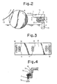
- FIG. 1 to FIG. 4 An embodiment of a wiping device of an intaglio printing press concerned with the present invention will be described by reference to FIG. 1 to FIG. 4, in which the same members as in FIG. 5 to FIG. 7 are assigned the same numerals, and overlapping explanations are omitted.
- the illustrated embodiment shows a wiping device of an intaglio printing press, which has a wiping roller 5 journaled in inner holes of right and left eccentric bearings 6 to move such that the peripheral surface of the wiping roller 5 contacts and leaves an intaglio surface (not shown) on an intaglio cylinder as the eccentric bearings 6 turn; and a doctor blade 1 held on a holder 2 such that the tip of the doctor blade 1 releasably contacts the peripheral surface of the wiping roller 5; in which the holder 2 is supported on a tank 3 on the machine body side so as to be movable in the directions of throw-on and throw-off of the doctor blade 1; and the eccentric bearings 6 and the opposite ends of the holder 2 are connected together by a cam mechanism 7 such that the holder 2 advances and retreats following the turns of the eccentric bearings 6.
- the holder 2 is supported on an upper surface of the tank 3 on the solvent 15 departing side of the wiping roller 5 by means of a plurality of (three in the drawing) long holes 10 formed with a predetermined spacing in the right-and-left direction and elongated in the back-and-forth direction, and by means of flanged pins 11 passing through these long holes 10.
- the holder 2 can move in the directions of throw-on and throw-off of the doctor blade 1, and can be prevented fromfloating from the tank 3.
- the long hole 10 and the flanged pin 11 located at one site in the center of the holder 2 restrain the movement of the holder 2 in the right-and-left direction.
- the long holes 10 and the flanged pins 11 other than those located at the one site in the center are constructed such that the flanged pin 11 has a smaller diameter than the minor diameter of the long hole 10.
- those other flanged pins 11 are fitted into those other long holes 10 with some play, so that they enable the holder 2 to move forward and backward (straightly) with some rightward and leftward play.
- the holder 2 is also adapted to advance and retreat in an interlocked relationship with the throw-on and throw-off of the wiping roller 5 to and from an intaglio cylinder 13 under the action of the cam mechanism 7.
- the cam mechanism 7 uses a spherical roller 7d as a cam follower at the front end of a lever 7c on the holder 2 side which engages a grooved cam 7a on the eccentric bearing 6 side.
- a sliding portion of the spherical roller 7d is surface treated with a self-lubricating rust preventive agent (e. g., chemical plating with Teflon Composite Nickel).
- a hydraulic cylinder 16 is attached to the holder 2, and an actuator portion of the hydraulic cylinder 16 is connected to the doctor 14 by a pin 17.
- the doctor 14 moves with respect to the holder 2, whereupon the doctor 14 can advance toward and retreat from the wiping roller 5 independently.
- the doctor 14 also moves with respect to the holder 2 by use of a threaded handle 18.
- the doctor 14 can be manually made to advance toward and retreatfrom the wiping roller 5.
- a doctor blade 1 as a blade extending along the axial direction of the wiping roller 5 is fixed, and is adapted to contact the peripheral surface of the wiping roller 5.
- the threaded handle 18 the doctor 14 is moved, thereby adjusting the gap between the doctor blade 1 and the wiping roller 5.
- the numeral 12 denotes a scale for use in fine adjustment of the gap by operating the threaded handle 18.
- a pointer (not shown) on the doctor 14 in combination with the scale enables the operator to make fine adjustment of the amount of the gap.
- the spherical roller 7d on the operator's side can be cocked about the spherical roller 7d on the drive side by moving the grooved cam 7a of the eccentric bearing 6 turned by the actuation of the hydraulic cylinder on the operator's side.
- the doctor blade 1 also moves obliquely and follows the above cocking motion, because of the aforementioned designs of the long holes 10 and flanged pins 11.
- the doctor blade 1 can satisfactorily follow the cocking of the wiping roller 5, thus completely preventing changes in the contact pressure or damage to parts owing to holdback of the movement of the doctor blade 1.
- the solvent or ink may penetrate through the opening of the dovetail groove, solidify or dry, holding back the movement of the doctor blade.
- the holder has no opening.
- the sliding portion of the spherical roller 7d is surface treated to impart anticorrosive and self-lubricating properties. This facilitates cleaning of ink and smoothes slides.
- the eccentric bearings and the holder are interlocked using the cam mechanism.
- any interlocking mechanism other than the cam mechanism may be used for interlock.
- the long holes formed at three spaced locations of the holder in its right-and-left direction and elongated in the back-and-forth direction of the holder, and the flanged pins passing through these long holes need not be provided on the right and left sides. It is permissible to provide a pin in the holder, and form an elongated hole in the tank. Alternatively, an elongated hole closed at its top may be provided in the holder, and a pin may be provided in the tank. The pin may be a straight pin, and need not be situated at the center. Instead of the long holes, long grooves each closed at the front end surface may be formed in the holder.
- the present invention can provide a wiping device of an intaglio printing press which has a wiping roller supported so as to be movable such that its peripheral surface contacts and leaves an intaglio surface on an intaglio cylinder, and supported so as to be capable of skewing adjustment relative to the intaglio surface; a holder for holding a doctor blade having a tip to be contacted with the peripheral surface of the wiping roller, the holder being supported movably on the machine body side; an interlocking mechanism connected to the wiping roller side such that the holder moves following the movement of the wiping roller; and a holder support means for supporting the holder on the machine body side such that the holder can move toward and away from the wiping roller and can turn following a skewing motion of the wiping roller, the holder support means being adapted to restrain the movement of the holder in the right-and-left direction.
- This wiping device enables the doctor blade to follow the cocking of the wiping rollereasily, and is
- a wiping device of an intaglio printing press in which a doctor blade can follow the movement of a wiping roller through an interlocking mechanism.
- the holder is supported on the machine body side by means of either a plurality of long holes or a plurality of long grooves and pin members so as to be movable in the directions of throw-on and throw-off of the doctor blade, the long holes or long grooves being formed in the holder in its right-and-left direction and elongated in its back-and-forth direction, the long grooves being each closed at the front end surface thereof, and the pin members passing through the long holes or long grooves; and the movement of the holder in the right-and-left direction is restrained by the long hole or long groove and the pin member that are located at one site in the center of the holder.
- a cam mechanism is used as the interlocking mechanism, and a spherical roller is used as the holder-side cam follower that engage the eccentric bearing-side grooved cam, the cam follower can respond to the cocking of the wiping roller, thus preventing an unwanted force.
Landscapes
- Engineering & Computer Science (AREA)
- Mechanical Engineering (AREA)
- Rotary Presses (AREA)
- Inking, Control Or Cleaning Of Printing Machines (AREA)
Abstract
Description
- This invention relates to a wiping device of an intaglio printing press which, after each printing, wipes off that surplus part of ink supplied to an intaglio surface which adheres to sites other than patterns.
- An intaglio printing press has an intaglio cylinderhaving an intaglio mounted on the peripheral surface thereof, and an impression cylinder contiguous to the intaglio cylinder. A paperto be printed is fed by a feeder, transported to a swing arm shaft pregripper, and then gripped by a gripper of the impression cylinder. The paper is printed with ink supplied to the plate surface of the intaglio to have images transferred thereto. A printed paper is delivered by a discharge chain for discharge.
- This type of intaglio printing press is equipped with a wiping device as disclosed, for example, in Japanese Patent Publication No. 47306/95. This wiping device comprises a wiping roller contiguous to the intaglio cylinder, and rotating such that the contiguous peripheral surfaces of the wiping roller and the intaglio cylinder move in opposite directions to each other; a plurality of brushes each having a pad surface contiguous to the peripheral surface of the wiping roller; and a doctor blade located downstream from the brushes in the direction of roller rotation and having a front end in contact with the wiping roller, the doctor blade being formed in the shape of a plate from an elastic material such as synthetic rubber. Part of ink, supplied from ink form rollers of an inking device to an intaglio surface, migrates and adheres to the surroundings of the ink-retaining cups as patterns. This surplus part of ink is wiped off with the wiping roller rotating in contact with the plate surface, and only the patterns of the cups are transferred to a paper. The wiping roller is rotating while being dipped in a solvent contained in a tank, such as trichloroethylene. The ink passed on to the wiping roller by the wiping-off action is removed with this solvent in combination with the washing action of the brushes. The solvent carried by the wiping roller is scraped off with the doctor blade into the solvent tank.
- With the ink wiping-off action by the wiping device, if the contact pressure of the wiping device on the plate surface is too high, even the ink of the cups as patterns will be scraped off, with the result that very thin lines cannot be printed. If the contact pressure is too low, surplus ink will remain in the surroundings of the cups. This will make the line widths of images wide, resulting in bleeding prints, or will cause the ink to remain in the whole of limited non-image areas, leaving considerable smears. To ensure the quality of prints, it is necessary to adjust the contact pressure of the wiping roller on the plate surface accurately. A conventional wiping device has a contact pressure adjusting device for this purpose. This type of conventional device for adjusting the contact pressure of a wiping roller journals the wiping roller by eccentric bearings, and turns these eccentric bearings by hydraulic cylinders, or turns the wiping roller by a handle device via a worm and a worm wheel, or via a screwed shaft, to move the wiping roller slightly toward and away from the plate surface. Another problem has been that if the contact pressure of the doctor blade is too high, the wiping roller will be damaged. If it is low, the solvent cannot be scraped off completely. In this case, the solvent may transfer from the wiping roller to the intaglio surface, and dissolve the ink adhering onto the intaglio surface, causing a printing trouble. Thus, it has been customary practice to provide a handle-operated contact pressure adjusting device for moving the tip of the doctor blade to and from the peripheral surface of the wiping roller. These two devices for adjusting contact pressure are used forth row-on and throw-off among the intaglio surface, the wiping roller, and the doctor blade.
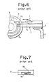
- In a conventional wiping device, as shown in FIG. 5 and FIG. 7, a
holder 2 for holding a doctor blade 1 is supported on an upper edge portion of atank 3, a support on the machine body side, by adovetail groove 4a formed on theholder 2 side and adovetail 4b formed on thetank 3 side. Theholder 2 is supported there so as to be movable in the directions of throw-on and throw-off of the doctor blade 1 with respect to thewiping roller 5. Theholder 2 is connected by acam mechanism 7 toeccentric bearings 6 which support thewiping roller 5. That is, alever 7c engaging agrooved cam 7a, formed on the eccentric bearing 6 side, via astraight pin 7b is secured to theholder 2. Thus, when theeccentric bearings 6 are rotated to adjust the contact pressure of thewiping roller 5 on the plate surface, the doctor plate 1 is moved in the directions of throw-on and throw-off to and from the wiping roller5 in an interlocked relationship with thecam mechanism 7 to make the contact pressure of the doctor blade 1 on thewiping roller 5 constant. - With the conventional wiping device, however, the doctor blade 1 makes only a linear motion because of the
dovetail groove 4a formed on theholder 2 side and thedovetail 4b formed on thetank 3 side. Moreover, the cam follower used is thestraight pin 7b. Thus, the following problems have been involved: - (1) If the wiping roller is subjected to skewing adjustment by the rotation of one of the eccentric bearings, the cam follower and the doctor blade are unable to follow the cocking, because they cannot move obliquely. Consequently, the doctor blade may move dully, and the parts may be broken.
- (2) The problem (1) occurs when the right and left hydraulic cylinders fail to move synchronously with the same phase during the throw-on and throw-off of the wiping roller.
- EP-A-0 357 825 discloses a wiping device of intaglio press comprising a wiping roller support so as to be movable such that a peripheral surface of said wiping roller contacts an leaves an intaglio surface of an intaglio cylinder. The wiping roller is capable of securing adjustment relative to the intaglio surface. The press further comprises a holder for holding a doctor blade having a tip to be contacted with the peripheral surface of the wiping roller and the holder is supported movably on the machine body side by a plurality of slots. An interlocking mechanism is connected to the wiping roller side such that the holder moves following the movement of the wiping roller. The holder is further movable toward and away from said wiping roller and can turn following a skewing motion of said wiping roller. Holder support means are adapted to restrain the movement of the holder in the right-and-left direction.
- DE-A-703 738 discloses a doctor blade device for an intaglio printing press wherein the doctor blade holder is self-aligning parallel to the printing cylinder surface. Such self-alignment is achieved by a pin being orthogonal relative to the plane of the doctor blade.
- This invention relates to a wiping device of an intaglio printing press as claimed in claim 1.
- It is an object of the present invention to provide a wiping device of an intaglio printing press in which a doctor blade can fully follow cocking of a wiping roller.
- To attain this object, the present invention is designed to have a wiping roller supported so as to be movable such that its peripheral surface contacts and leaves an intaglio surface on an intaglio cylinder, and supported so as to be capable of skewing adjustment relative to the intaglio surface; a holder for holding a doctor blade having a tip to be contacted with the peripheral surface of the wiping roller, the holder being supported movably on the machine body side; an interlocking mechanism connected to the wiping roller side such that the holder moves following the movement of the wiping roller; and a holder support means for supporting the holder on the machine body side such that the holder can move toward and away from the wiping roller and can turn following a skewing motion of the wiping roller, the holder support means being adapted to restrain the movement of the holder in the right-and-left direction.
- According to this design, the doctor blade can make a swinging (oblique) motion in addition to a linear motion. Its swing enables the doctor blade to follow the cocking of the wiping roller.
- Another aspect of the present invention is a wiping device of an intaglio printing press which comprises a wiping roller movable such that its peripheral surface contacts and leaves an intaglio surface on an intaglio cylinder, and a doctor blade held on a holder such that the tip of the doctor blade releasably contacts the peripheral surface of the wiping roller, the holder being supported on the machine body side so as to be movable in the directions of throw-on and throw-off of the doctor blade, and being connected to the wiping roller side by an interlocking mechanism such that the holder advances and retreats following the movement of the wiping roller; wherein
the holder is supported on the machine body side by means of either a plurality of long holes or a plurality of long grooves and pin members so as to be movable in the directions of throw-on and throw-off of the doctor blade, the long holes or long grooves being formed in the holder in its right-and-left direction and elongated in its back-and-forth direction, the long grooves being each closed at the front end surface thereof, and the pin members passing through the long holes or long grooves; and the movement of the holder in the right-and-left direction is restrained by the long hole or long groove and the pin member that are located at one site in the center of the holder. - According to the above aspect of the invention, a simple configuration enables the doctor blade to make a swinging (oblique) motion in addition to a linear motion. This swing permits the doctor blade to follow the cocking of the wiping roller.
- The interlocking mechanism is a cam mechanism. Preferably, a spherical roller is used as the cam follower on the holder side that engages the grooved cam on the eccentric bearing side. By so doing, the cam follower can fully respond to the cocking of the wiping roller, thus preventing an unwanted force.
- The present invention will become more fully understood from the following detailed description in conjunction with the accompanying drawings which are given for the purpose of illustration only, and thus are not limitative, and wherein:
- FIG. 1 is a plan view of an essential part of a wiping device concerned with an embodiment of the present invention;
- FIG. 2 is a side view of the essential part of the wiping device;
- FIG. 3 is a view taken on line A-A of FIG. 2;
- FIG. 4 is a sectional view of an essential part of a cam mechanism in the wiping device;
- FIG. 5 is a plan view of an essential part of a conventional wiping device;
- FIG. 6 is a side view of the essential part of the conventional wiping device; and
- FIG. 7 is a detail view of a sliding portion of a holder in the conventional wiping device.
- An embodiment of a wiping device of an intaglio printing press concerned with the present invention will be described by reference to FIG. 1 to FIG. 4, in which the same members as in FIG. 5 to FIG. 7 are assigned the same numerals, and overlapping explanations are omitted.
- The illustrated embodiment shows a wiping device of an intaglio printing press, which has a wiping
roller 5 journaled in inner holes of right and lefteccentric bearings 6 to move such that the peripheral surface of the wipingroller 5 contacts and leaves an intaglio surface (not shown) on an intaglio cylinder as theeccentric bearings 6 turn; and a doctor blade 1 held on aholder 2 such that the tip of the doctor blade 1 releasably contacts the peripheral surface of the wipingroller 5; in which theholder 2 is supported on atank 3 on the machine body side so as to be movable in the directions of throw-on and throw-off of the doctor blade 1; and theeccentric bearings 6 and the opposite ends of theholder 2 are connected together by acam mechanism 7 such that theholder 2 advances and retreats following the turns of theeccentric bearings 6. - In the instant embodiment, the
holder 2 is supported on an upper surface of thetank 3 on the solvent 15 departing side of the wipingroller 5 by means of a plurality of (three in the drawing)long holes 10 formed with a predetermined spacing in the right-and-left direction and elongated in the back-and-forth direction, and by means offlanged pins 11 passing through theselong holes 10. Thus, theholder 2 can move in the directions of throw-on and throw-off of the doctor blade 1, and can be prevented fromfloating from thetank 3. Thelong hole 10 and theflanged pin 11 located at one site in the center of theholder 2 restrain the movement of theholder 2 in the right-and-left direction. Thelong holes 10 and theflanged pins 11 other than those located at the one site in the center are constructed such that theflanged pin 11 has a smaller diameter than the minor diameter of thelong hole 10. Thus, those otherflanged pins 11 are fitted into those otherlong holes 10 with some play, so that they enable theholder 2 to move forward and backward (straightly) with some rightward and leftward play. Theholder 2 is also adapted to advance and retreat in an interlocked relationship with the throw-on and throw-off of the wipingroller 5 to and from anintaglio cylinder 13 under the action of thecam mechanism 7. Thecam mechanism 7 uses aspherical roller 7d as a cam follower at the front end of alever 7c on theholder 2 side which engages agrooved cam 7a on theeccentric bearing 6 side. A sliding portion of thespherical roller 7d is surface treated with a self-lubricating rust preventive agent (e. g., chemical plating with Teflon Composite Nickel). - A
hydraulic cylinder 16 is attached to theholder 2, and an actuator portion of thehydraulic cylinder 16 is connected to thedoctor 14 by apin 17. Upon actuation of thehydraulic cylinder 16, thedoctor 14 moves with respect to theholder 2, whereupon thedoctor 14 can advance toward and retreat from the wipingroller 5 independently. Thedoctor 14 also moves with respect to theholder 2 by use of a threadedhandle 18. Thus, thedoctor 14 can be manually made to advance toward and retreatfrom the wipingroller 5. To thedoctor 14, a doctor blade 1 as a blade extending along the axial direction of the wipingroller 5 is fixed, and is adapted to contact the peripheral surface of the wipingroller 5. By operating the threadedhandle 18, thedoctor 14 is moved, thereby adjusting the gap between the doctor blade 1 and the wipingroller 5. In FIG. 3, the numeral 12 denotes a scale for use in fine adjustment of the gap by operating the threadedhandle 18. A pointer (not shown) on thedoctor 14 in combination with the scale enables the operator to make fine adjustment of the amount of the gap. - According to the above-described configuration, when the nip pressure between the intaglio cylinder and the wiping
roller 5 is adjusted, theholder 2 moves with respect to thetank 3 in the directions of throw-on and throw-off of the doctor blade 1 via the cam mechanism in accordance with the turns of the right and lefteccentric bearings 6. Thus, the pressure of contact between the wipingroller 5 and the doctor blade 1 does not change. - When the wiping
roller 5, for example, on the operator's side of the printing press is to be cocked, thespherical roller 7d on the operator's side can be cocked about thespherical roller 7d on the drive side by moving thegrooved cam 7a of theeccentric bearing 6 turned by the actuation of the hydraulic cylinder on the operator's side. On this occasion, the doctor blade 1 also moves obliquely and follows the above cocking motion, because of the aforementioned designs of thelong holes 10 and flanged pins 11. - As noted above, the doctor blade 1 can satisfactorily follow the cocking of the wiping
roller 5, thus completely preventing changes in the contact pressure or damage to parts owing to holdback of the movement of the doctor blade 1. With a conventional configuration, the solvent or ink may penetrate through the opening of the dovetail groove, solidify or dry, holding back the movement of the doctor blade. According to the configuration of the instant embodiment, on the other hand, the holder has no opening. Thus, the penetration of the solvent or ink into the sliding surfaces can be prevented, whereby the holdback of slides can be inhibited and maintenance becomes easier. Furthermore, the sliding portion of thespherical roller 7d is surface treated to impart anticorrosive and self-lubricating properties. This facilitates cleaning of ink and smoothes slides. - In the foregoing embodiment, the eccentric bearings and the holder are interlocked using the cam mechanism. However, any interlocking mechanism other than the cam mechanism may be used for interlock. The long holes formed at three spaced locations of the holder in its right-and-left direction and elongated in the back-and-forth direction of the holder, and the flanged pins passing through these long holes need not be provided on the right and left sides. It is permissible to provide a pin in the holder, and form an elongated hole in the tank. Alternatively, an elongated hole closed at its top may be provided in the holder, and a pin may be provided in the tank. The pin may be a straight pin, and need not be situated at the center. Instead of the long holes, long grooves each closed at the front end surface may be formed in the holder.
- As described above, the present invention can provide a wiping device of an intaglio printing press which has a wiping roller supported so as to be movable such that its peripheral surface contacts and leaves an intaglio surface on an intaglio cylinder, and supported so as to be capable of skewing adjustment relative to the intaglio surface; a holder for holding a doctor blade having a tip to be contacted with the peripheral surface of the wiping roller, the holder being supported movably on the machine body side; an interlocking mechanism connected to the wiping roller side such that the holder moves following the movement of the wiping roller; and a holder support means for supporting the holder on the machine body side such that the holder can move toward and away from the wiping roller and can turn following a skewing motion of the wiping roller, the holder support means being adapted to restrain the movement of the holder in the right-and-left direction. This wiping device enables the doctor blade to follow the cocking of the wiping rollereasily, and is free from possible troubles due to the penetration of the solvent or ink.
- As another aspect of the invention, there can be provided a wiping device of an intaglio printing press in which a doctor blade can follow the movement of a wiping roller through an interlocking mechanism. In this wiping device, the holder is supported on the machine body side by means of either a plurality of long holes or a plurality of long grooves and pin members so as to be movable in the directions of throw-on and throw-off of the doctor blade, the long holes or long grooves being formed in the holder in its right-and-left direction and elongated in its back-and-forth direction, the long grooves being each closed at the front end surface thereof, and the pin members passing through the long holes or long grooves; and the movement of the holder in the right-and-left direction is restrained by the long hole or long groove and the pin member that are located at one site in the center of the holder. Thus, a simple configuration enables the doctor blade to follow the cocking of the wiping roller easily, and the wiping device is free from troubles due to the penetration of the solvent or ink.
- If a cam mechanism is used as the interlocking mechanism, and a spherical roller is used as the holder-side cam follower that engage the eccentric bearing-side grooved cam, the cam follower can respond to the cocking of the wiping roller, thus preventing an unwanted force.
- While the present invention has been described in the foregoing fashion, it is to be understood that the invention is not limited thereby, but may be varied in many other ways. Such variations are not to be regarded as a departure from the scope of the invention, and all such modifications as would be obvious to one skilled in the art are intended to be included within the scope of the following claims.
Claims (3)
- A wiping device of an intaglio printing press, comprising:a wiping roller (5) supported so as to be movable such that the peripheral surface of said wiping roller (5) contacts and leaves an intaglio surface on an intaglio cylinder (13); and supported so as to be capable of skewing adjustment relative to said intaglio surface;a holder (2) for holding a doctor blade (1) having a tip to be contacted with the peripheral surface of said wiping roller (5), said holder (2) being supported movably on the machine body side by a plurality of long holes (10) or long grooves being each closed at the front and surface thereof and flanged pins (11);an interlocking mechanism (7) connected to the wiping roller (5) side such that said holder (2) moves following the movement of said wiping roller(5);said long holes (10) or long grooves and pins (11) supporting said holder (2) on the machine body side such that said holder (2) can move toward and away from said wiping roller (5) and can turn following a skewing motion of said wiping roller (5); said holder support means (10, 11) being adapted to restrain the movement of said holder (2) in the right-and-left direction.
- A wiping device as claimed in claim 1, wherein
said holder (2) is supported on the machine body side by means of either a plurality of long holes (10) or a plurality of long grooves and pin members (11) so as to be movable in the directions of throw-on and throw-off of said doctor blade (1);
said long holes (10) or long grooves being formed in said holder (2) in its right-and-left direction and elongated in its back-and-forth direction, said long grooves being each closed at the front end surface thereof, and said pin members (11) passing through said long holes (10) or long grooves; and
the movement of said holder (2) in the right-and-left direction is restrained by said long hole (10) or long groove and said pin member (11) that are located at one site in the centre of said holder (2). - The wiping device of claim 1 or 2, wherein said interlocking mechan ism (7) is a cam mechanism comprising a grooved cam (7a) on the eccentric bearing (6) side, and a spherical roller (7d) used as a cam follower on the holder side, said cam follower engaging said grooved cam (7a).
Applications Claiming Priority (3)
| Application Number | Priority Date | Filing Date | Title |
|---|---|---|---|
| JP248977/95 | 1995-09-27 | ||
| JP24897795A JP3421485B2 (en) | 1995-09-27 | 1995-09-27 | Wiping device for intaglio printing press |
| JP24897795 | 1995-09-27 |
Publications (3)
| Publication Number | Publication Date |
|---|---|
| EP0765745A1 EP0765745A1 (en) | 1997-04-02 |
| EP0765745B1 EP0765745B1 (en) | 2001-11-28 |
| EP0765745B2 true EP0765745B2 (en) | 2006-01-18 |
Family
ID=17186204
Family Applications (1)
| Application Number | Title | Priority Date | Filing Date |
|---|---|---|---|
| EP96250213A Expired - Lifetime EP0765745B2 (en) | 1995-09-27 | 1996-09-25 | Wiping device of intaglio printing press |
Country Status (5)
| Country | Link |
|---|---|
| US (1) | US5765480A (en) |
| EP (1) | EP0765745B2 (en) |
| JP (1) | JP3421485B2 (en) |
| AT (1) | ATE209568T1 (en) |
| DE (1) | DE69617351T3 (en) |
Families Citing this family (5)
| Publication number | Priority date | Publication date | Assignee | Title |
|---|---|---|---|---|
| AU762106B2 (en) * | 1999-06-22 | 2003-06-19 | Tresu Production A/S | Doctor blade system |
| EP1844930A1 (en) | 2006-04-11 | 2007-10-17 | Kba-Giori S.A. | Ink wiping system for a printing machine |
| ES2375886T3 (en) | 2007-04-27 | 2012-03-07 | Bobst Sa | SCRAP SYSTEM FOR PRINTER GROUP INTENDED FOR A HELIOGRABATE PRINTING MACHINE. |
| EP2524805A1 (en) * | 2011-05-20 | 2012-11-21 | KBA-NotaSys SA | Ink wiping system for an intaglio printing press |
| EP2524809A1 (en) * | 2011-05-20 | 2012-11-21 | KBA-NotaSys SA | Ink wiping system for an intaglio printing press |
Citations (2)
| Publication number | Priority date | Publication date | Assignee | Title |
|---|---|---|---|---|
| US509528A (en) † | 1893-11-28 | Teansfees from engeaved eolls | ||
| US2104985A (en) † | 1936-07-14 | 1938-01-11 | Shellmar Products Co | Intaglio printing device |
Family Cites Families (6)
| Publication number | Priority date | Publication date | Assignee | Title |
|---|---|---|---|---|
| GB187291A (en) * | 1921-07-11 | 1922-10-11 | George William Mascord | Improvements relating to printing machines |
| DE703738C (en) * | 1939-05-31 | 1941-03-14 | Vomag Maschinenfabrik A G | Squeegee device for gravure printing machines |
| US3252416A (en) * | 1964-04-28 | 1966-05-24 | James O Allen | Method and apparatus for removing foreign matter from a planographic printing press plate cylinder |
| US3593663A (en) * | 1969-06-03 | 1971-07-20 | Zerand Corp | Doctor blade assembly for printing equipment |
| US3780670A (en) * | 1972-08-07 | 1973-12-25 | Faustel Inc | Doctor blade assembly |
| DE3886399T3 (en) * | 1988-09-08 | 2002-07-04 | Komori Corporation, Tokio/Tokyo | Doctor device for gravure printing machines. |
-
1995
- 1995-09-27 JP JP24897795A patent/JP3421485B2/en not_active Expired - Fee Related
-
1996
- 1996-09-25 DE DE69617351T patent/DE69617351T3/en not_active Expired - Lifetime
- 1996-09-25 EP EP96250213A patent/EP0765745B2/en not_active Expired - Lifetime
- 1996-09-25 AT AT96250213T patent/ATE209568T1/en not_active IP Right Cessation
- 1996-09-27 US US08/721,960 patent/US5765480A/en not_active Expired - Lifetime
Patent Citations (2)
| Publication number | Priority date | Publication date | Assignee | Title |
|---|---|---|---|---|
| US509528A (en) † | 1893-11-28 | Teansfees from engeaved eolls | ||
| US2104985A (en) † | 1936-07-14 | 1938-01-11 | Shellmar Products Co | Intaglio printing device |
Also Published As
| Publication number | Publication date |
|---|---|
| JP3421485B2 (en) | 2003-06-30 |
| EP0765745A1 (en) | 1997-04-02 |
| DE69617351D1 (en) | 2002-01-10 |
| DE69617351T2 (en) | 2002-07-18 |
| US5765480A (en) | 1998-06-16 |
| EP0765745B1 (en) | 2001-11-28 |
| ATE209568T1 (en) | 2001-12-15 |
| DE69617351T3 (en) | 2006-08-31 |
| JPH0985931A (en) | 1997-03-31 |
Similar Documents
| Publication | Publication Date | Title |
|---|---|---|
| US3780670A (en) | Doctor blade assembly | |
| US4922818A (en) | Wetting/inking mechanism for offset printing presses | |
| US5375522A (en) | Method and apparatus for washing a printing press in conjunction with a damping unit | |
| EP0967078B1 (en) | Web press with a throw-on and a throw-off mechanism | |
| EP0765745B2 (en) | Wiping device of intaglio printing press | |
| JPH05154999A (en) | Printing unit | |
| US3146706A (en) | Dampening system for lithographic printing presses | |
| US5460088A (en) | Printing press | |
| US4414897A (en) | Inking mechanism in a rotary press | |
| GB2266272A (en) | Doctor blade bar for rotary printing press | |
| US5452660A (en) | Washing device selectively engageable with plural inking paths | |
| CA1066130A (en) | Ink ductor system | |
| US4833988A (en) | Inking device for printing apparatus | |
| US5086696A (en) | Wetting/inking mechanism for offset printing presses | |
| US20010029858A1 (en) | Printing machine | |
| US4821641A (en) | Dampening and bridging apparatus for a duplicating machine | |
| EP1044814B1 (en) | Device for cleaning the surface of bearer rings of rotating cylinders in rotary presses | |
| JP3785213B2 (en) | Inking device of printing machine | |
| JP2875856B2 (en) | Swing rider drive | |
| US2832286A (en) | Apparatus for removing ink from a printing plate | |
| EP1975316A1 (en) | Doctor device and blade exchange method for doctor device | |
| CA1240203A (en) | Dampening system for printing machines | |
| US3625144A (en) | Skewing device for dampener of offset printing press | |
| SU1659227A1 (en) | Inking mechanism for flexographic printing | |
| DE493395C (en) | Multicolor rotogravure printing machine |
Legal Events
| Date | Code | Title | Description |
|---|---|---|---|
| PUAI | Public reference made under article 153(3) epc to a published international application that has entered the european phase |
Free format text: ORIGINAL CODE: 0009012 |
|
| AK | Designated contracting states |
Kind code of ref document: A1 Designated state(s): AT CH DE FR GB IT LI NL SE |
|
| 17P | Request for examination filed |
Effective date: 19970825 |
|
| 17Q | First examination report despatched |
Effective date: 19980717 |
|
| GRAG | Despatch of communication of intention to grant |
Free format text: ORIGINAL CODE: EPIDOS AGRA |
|
| GRAG | Despatch of communication of intention to grant |
Free format text: ORIGINAL CODE: EPIDOS AGRA |
|
| GRAH | Despatch of communication of intention to grant a patent |
Free format text: ORIGINAL CODE: EPIDOS IGRA |
|
| GRAH | Despatch of communication of intention to grant a patent |
Free format text: ORIGINAL CODE: EPIDOS IGRA |
|
| GRAA | (expected) grant |
Free format text: ORIGINAL CODE: 0009210 |
|
| AK | Designated contracting states |
Kind code of ref document: B1 Designated state(s): AT CH DE FR GB IT LI NL SE |
|
| REF | Corresponds to: |
Ref document number: 209568 Country of ref document: AT Date of ref document: 20011215 Kind code of ref document: T |
|
| REG | Reference to a national code |
Ref country code: CH Ref legal event code: EP |
|
| REG | Reference to a national code |
Ref country code: GB Ref legal event code: IF02 |
|
| REF | Corresponds to: |
Ref document number: 69617351 Country of ref document: DE Date of ref document: 20020110 |
|
| REG | Reference to a national code |
Ref country code: CH Ref legal event code: NV Representative=s name: PATENTANWALTSBUREAU R. A. MASPOLI |
|
| ET | Fr: translation filed | ||
| PLBQ | Unpublished change to opponent data |
Free format text: ORIGINAL CODE: EPIDOS OPPO |
|
| PLBI | Opposition filed |
Free format text: ORIGINAL CODE: 0009260 |
|
| PLBF | Reply of patent proprietor to notice(s) of opposition |
Free format text: ORIGINAL CODE: EPIDOS OBSO |
|
| 26 | Opposition filed |
Opponent name: KBA-GIORI S.A. Effective date: 20020827 |
|
| NLR1 | Nl: opposition has been filed with the epo |
Opponent name: KBA-GIORI S.A. |
|
| PLBF | Reply of patent proprietor to notice(s) of opposition |
Free format text: ORIGINAL CODE: EPIDOS OBSO |
|
| PUAH | Patent maintained in amended form |
Free format text: ORIGINAL CODE: 0009272 |
|
| STAA | Information on the status of an ep patent application or granted ep patent |
Free format text: STATUS: PATENT MAINTAINED AS AMENDED |
|
| PLAB | Opposition data, opponent's data or that of the opponent's representative modified |
Free format text: ORIGINAL CODE: 0009299OPPO |
|
| 27A | Patent maintained in amended form |
Effective date: 20060118 |
|
| AK | Designated contracting states |
Kind code of ref document: B2 Designated state(s): AT CH DE FR GB IT LI NL SE |
|
| R26 | Opposition filed (corrected) |
Opponent name: KBA-GIORI S.A. Effective date: 20020827 |
|
| REG | Reference to a national code |
Ref country code: CH Ref legal event code: AEN Free format text: AUFRECHTERHALTUNG DES PATENTES IN GEAENDERTER FORM |
|
| NLR2 | Nl: decision of opposition |
Effective date: 20060118 |
|
| REG | Reference to a national code |
Ref country code: SE Ref legal event code: RPEO |
|
| NLR3 | Nl: receipt of modified translations in the netherlands language after an opposition procedure | ||
| ET3 | Fr: translation filed ** decision concerning opposition | ||
| PGFP | Annual fee paid to national office [announced via postgrant information from national office to epo] |
Ref country code: NL Payment date: 20080915 Year of fee payment: 13 Ref country code: IT Payment date: 20080926 Year of fee payment: 13 Ref country code: FR Payment date: 20080915 Year of fee payment: 13 Ref country code: AT Payment date: 20080912 Year of fee payment: 13 |
|
| PGFP | Annual fee paid to national office [announced via postgrant information from national office to epo] |
Ref country code: SE Payment date: 20080908 Year of fee payment: 13 |
|
| PGFP | Annual fee paid to national office [announced via postgrant information from national office to epo] |
Ref country code: GB Payment date: 20081001 Year of fee payment: 13 |
|
| PGFP | Annual fee paid to national office [announced via postgrant information from national office to epo] |
Ref country code: DE Payment date: 20090917 Year of fee payment: 14 Ref country code: CH Payment date: 20091006 Year of fee payment: 14 |
|
| REG | Reference to a national code |
Ref country code: NL Ref legal event code: V1 Effective date: 20100401 |
|
| EUG | Se: european patent has lapsed | ||
| GBPC | Gb: european patent ceased through non-payment of renewal fee |
Effective date: 20090925 |
|
| REG | Reference to a national code |
Ref country code: FR Ref legal event code: ST Effective date: 20100531 |
|
| PG25 | Lapsed in a contracting state [announced via postgrant information from national office to epo] |
Ref country code: AT Free format text: LAPSE BECAUSE OF NON-PAYMENT OF DUE FEES Effective date: 20090925 |
|
| PG25 | Lapsed in a contracting state [announced via postgrant information from national office to epo] |
Ref country code: NL Free format text: LAPSE BECAUSE OF NON-PAYMENT OF DUE FEES Effective date: 20100401 Ref country code: FR Free format text: LAPSE BECAUSE OF NON-PAYMENT OF DUE FEES Effective date: 20090930 |
|
| PG25 | Lapsed in a contracting state [announced via postgrant information from national office to epo] |
Ref country code: GB Free format text: LAPSE BECAUSE OF NON-PAYMENT OF DUE FEES Effective date: 20090925 |
|
| PG25 | Lapsed in a contracting state [announced via postgrant information from national office to epo] |
Ref country code: IT Free format text: LAPSE BECAUSE OF NON-PAYMENT OF DUE FEES Effective date: 20090925 |
|
| REG | Reference to a national code |
Ref country code: CH Ref legal event code: PL |
|
| PG25 | Lapsed in a contracting state [announced via postgrant information from national office to epo] |
Ref country code: SE Free format text: LAPSE BECAUSE OF NON-PAYMENT OF DUE FEES Effective date: 20090926 |
|
| REG | Reference to a national code |
Ref country code: DE Ref legal event code: R119 Ref document number: 69617351 Country of ref document: DE Effective date: 20110401 |
|
| PG25 | Lapsed in a contracting state [announced via postgrant information from national office to epo] |
Ref country code: LI Free format text: LAPSE BECAUSE OF NON-PAYMENT OF DUE FEES Effective date: 20100930 Ref country code: CH Free format text: LAPSE BECAUSE OF NON-PAYMENT OF DUE FEES Effective date: 20100930 Ref country code: DE Free format text: LAPSE BECAUSE OF NON-PAYMENT OF DUE FEES Effective date: 20110401 |