EP0765594B1 - Vorrichtung zur Steuerung eines Gerätes, dessen Position einstellbar ist - Google Patents
Vorrichtung zur Steuerung eines Gerätes, dessen Position einstellbar ist Download PDFInfo
- Publication number
- EP0765594B1 EP0765594B1 EP96202420A EP96202420A EP0765594B1 EP 0765594 B1 EP0765594 B1 EP 0765594B1 EP 96202420 A EP96202420 A EP 96202420A EP 96202420 A EP96202420 A EP 96202420A EP 0765594 B1 EP0765594 B1 EP 0765594B1
- Authority
- EP
- European Patent Office
- Prior art keywords
- header
- implement
- signals
- vehicle
- relative
- Prior art date
- Legal status (The legal status is an assumption and is not a legal conclusion. Google has not performed a legal analysis and makes no representation as to the accuracy of the status listed.)
- Expired - Lifetime
Links
- 238000003306 harvesting Methods 0.000 claims description 9
- 238000005188 flotation Methods 0.000 claims description 7
- 230000001419 dependent effect Effects 0.000 claims 1
- 230000003287 optical effect Effects 0.000 description 5
- 230000008859 change Effects 0.000 description 4
- 239000011435 rock Substances 0.000 description 4
- 238000013461 design Methods 0.000 description 3
- 238000002604 ultrasonography Methods 0.000 description 3
- 238000010586 diagram Methods 0.000 description 2
- 230000007246 mechanism Effects 0.000 description 2
- 241001124569 Lycaenidae Species 0.000 description 1
- 238000013459 approach Methods 0.000 description 1
- 230000008901 benefit Effects 0.000 description 1
- 238000000151 deposition Methods 0.000 description 1
- 238000011161 development Methods 0.000 description 1
- 239000000428 dust Substances 0.000 description 1
- 238000005259 measurement Methods 0.000 description 1
- 238000000034 method Methods 0.000 description 1
- OCDRLZFZBHZTKQ-NMUBGGKPSA-N onetine Chemical compound C[C@@H](O)[C@@]1(O)C[C@@H](C)[C@@](C)(O)C(=O)OC\C2=C\CN(C)CC[C@@H](OC1=O)C2=O OCDRLZFZBHZTKQ-NMUBGGKPSA-N 0.000 description 1
- 230000008569 process Effects 0.000 description 1
- 230000035484 reaction time Effects 0.000 description 1
- 230000004044 response Effects 0.000 description 1
- 239000010902 straw Substances 0.000 description 1
Images


Classifications
-
- A—HUMAN NECESSITIES
- A01—AGRICULTURE; FORESTRY; ANIMAL HUSBANDRY; HUNTING; TRAPPING; FISHING
- A01D—HARVESTING; MOWING
- A01D41/00—Combines, i.e. harvesters or mowers combined with threshing devices
- A01D41/12—Details of combines
- A01D41/14—Mowing tables
- A01D41/141—Automatic header control
-
- Y—GENERAL TAGGING OF NEW TECHNOLOGICAL DEVELOPMENTS; GENERAL TAGGING OF CROSS-SECTIONAL TECHNOLOGIES SPANNING OVER SEVERAL SECTIONS OF THE IPC; TECHNICAL SUBJECTS COVERED BY FORMER USPC CROSS-REFERENCE ART COLLECTIONS [XRACs] AND DIGESTS
- Y10—TECHNICAL SUBJECTS COVERED BY FORMER USPC
- Y10S—TECHNICAL SUBJECTS COVERED BY FORMER USPC CROSS-REFERENCE ART COLLECTIONS [XRACs] AND DIGESTS
- Y10S56/00—Harvesters
- Y10S56/15—Condition responsive
Definitions
- This invention relates to an apparatus for controlling the position, especially the height, relative to a surface of a position-adjustable implement, in particular but not exclusively, carried by a vehicle movable over such a surface.
- the invention relates to an apparatus for controlling the height relative to ground of a height-adjustable implement on an agricultural vehicle such as a harvesting machine, in particular a combine harvester.
- US-A-3,722,193 and US-A-3,953,959 disclose arrangements including ground-sensing members that are pivotably secured to the header of a harvesting machine. As the header encounters a change in the terrain, the ground-sensing members pivot in response and send electrical signals to a control circuit. This, in turn, operates actuators that raise or lower the header in order to maintain it at a constant distance from the surface of the ground.
- an apparatus for controlling the position of a position-adjustable implement relative to a surface comprising:
- this arrangement advantageously permits sensing of the position of an implement at a location remote from a crop-cutting area thereof.
- the first member can be constructed as a robust item.
- the first member is pivotably secured on these implements.
- the further member is rigidly secured to the first member.
- further operative mechanisms such as linkages, gears, actuators and/or resilient members providing an operative connection between the first member and the further member.
- the apparatus is carried by a vehicle, such as a combine harvester, moveable over a surface and the signal relaying portion lies rearwardly of the implement when the vehicle is moving forwardly over the surface.
- the configuration of the first member and the further member minimises the chance of the first member digging into the ground.
- the first member is constituted as a shoe such as the shoes of a harvesting machine header.
- the signal relaying portion includes a reflecting portion that preferably is a surface of, or secured to, the further member.
- the surface is generally flat; in an alternative embodiment, the surface is at least partly non-planar, for example saw-toothed.
- the source of signals includes a signal transmitter, spaced from the relaying portion, for transmitting signals thereto.
- the transmitter emits and the receiver receives sonic signals.
- the signal receiver is spaced from the reflecting portion by a distance in the range of 20 to 60 cms. This advantageously allows the use of preferred receiving devices that operate in sonic wavelength ranges.
- a preferred sensing device is known as Bosch Sensor 0538009250.
- the apparatus includes means for limiting movement of the first member.
- the apparatus may also optionally include a latch for temporarily securing the first member against movement.
- the apparatus includes two or more first members as aforesaid and a corresponding number of further members, signal relaying portions, sources of signals and signal receivers.
- the first members are arranged in operative pairs, whereby adjustment of the implement occurs when movement of both members of a said pair is detected by the controller.
- the invention is also considered to reside in a vehicle incorporating apparatus as aforesaid, in particular a harvesting machine and further in particular a harvesting machine having a header including at least one pivotable shoe constituting the first member.
- a vehicle may include a pair of such pivotable shoes constituting a pair of first members and optionally one or more fixed shoes of a conventional design.
- the respective first members may be spaced from one another, with one or more fixed shoes as aforesaid interposed therebetween.
- the controller may be configured selectively to operate the header in known height adjustment, lateral flotation and compensation modes.
- the invention is also considered to reside in a position adjustment apparatus for an agricultural implement, employing an ultrasound distance sensor, the spacing between the signal emitter/receiver and signal reflecting part of which is in the range of 20 to 60 cms.
- header 10 of a combine harvester the header including a trough 11 essentially of conventional design surrounding a conventional auger 12. At the forward edge of a lower wall 11a of the header 10 defined by trough 11, there is secured a conventional cutterbar 13.
- a conventional reel mounted on reel arms 15 is shown only schematically at 14, which reference numeral signifies the axis of the reel.
- One tine 16 of the reel 14 is shown at its lowermost position, just above the ground surface 17.
- the header 10 also includes conventional crop dividers 21 at each transverse end.
- the lower wall 11a of the header 10 defined by trough 11 extends in a conventional manner across the width of the header.
- a series of fixed shoes 18 are secured to the underside of lower wall 11a, so as to provide a fixed shoe zone 19 extending across the central portion of the underside of the header 10.
- Respective pivotable shoes 20a, 20b are secured on the underside of wall 11a at the respective extreme ends thereof, beyond the fixed shoe zone 19.
- Each pivotable shoe 20a, 20b is pivotably secured at its forwardmost end (as defined by the direction of forward movement of the vehicle, indicated by the arrows A) to the underside of lower wall 11a by means of a suitable hinge or pivot 22.
- Each pivotable shoe 20a, 20b extends rearwardly and downwardly of the associated pivot 22 in a generally arcuate manner. Approximately two thirds of the way along its length, each pivotable shoe 20a, 20b then curves upwardly to define: (i) a portion 23 intended to engage and ride upon the ground surface 17; and (ii) a further member 24 extending upwardly and rearwardly beyond a lower main transverse beam 25 of the header 10.
- Each further member 24 terminates in an upwardly-directed surface 26 secured thereto or integral therewith.
- a support bracket 28 is secured to and extends rearwardly of trough 11 so as to support a transceiver 29 spaced above the surface 26.
- surface 26 extends only part-way across the width of each respective pivotable shoe 20a, 20b; however, it is possible to devise embodiments in which the surface 26 extends across the entire width of each pivotable shoe with which it is associated.
- pivotable shoes 20a, 20b are movable in a vertical plane of movement. Movement of the pivotable shoes 20a, 20b is limited to the angle 27 indicated by the dotted lines in Figure 1. This is achieved firstly by virtue of each pivotable shoe 20a, 20b being engageable with a downwardly-extending part on the underside of the header trough 11 such as the main beam 25 thereof or a resilient stop provided thereon; and secondly by virtue of eg. a chain or similar flexible member interconnecting each pivotable shoe 20a, 20b and the underside of the header trough 11 in order to limit the downward movement of each said pivotable shoe.
- the pivotable shoes 20a, 20b move within the angular range 27 by virtue of engagement of their respective undersides 23 with the ground surface 17. Consequently, the distance between surface 26 and transceiver 29 is directly indicative of the height of the header 10 above the ground surface 17 in the sense that, as this distance is reduced, the height of the header 10 above the ground is increased.
- the transceiver 29 is an ultrasound device.
- the surface 26 is formed with irregularities or corrugations, in order to ensure reflection of ultrasound signals therefrom back to the emitter/receiver 29 regardless of the angle of surface 26, which angle will, of course, change as the height of header 10 relative to ground surface 17 is varied.
- the header 10 may be provided with a latching mechanism (that may be of conventional design) for locking the pivotable shoes 20a, 20b in a raised position relative to the underside of the header 10.
- a latching mechanism that may be of conventional design
- the header 10 is suspended in a conventional manner in the vehicle so as to ride with a predetermined minimal ground pressure on the ground surface 17.
- This feature is further also advantageous for facilitating the depositing of the header 10 on a header transport wagon for road transport purposes.
- the pivotable shoes 20a, 20b are each approximately of the same width as the respective fixed shoes 18 which may be in the range of 50 to 150 cms. This advantageously prevents the apparatus from falsely adjusting the height of header 10 when one of the pivotable shoes 20a, 20b encounters a narrow recess or protuberance forming part of ground surface 17.
- the header 10 could also be arranged to function with much narrower pivotable shoes in the range of a few centimetres only. In such an embodiment (not shown in the drawings), it would be desirable to provide such narrow, pivotable shoes in pairs with the members of each pair lying a predetermined distance apart.
- the pivotable shoes and/or the control circuit could be configured only to adjust the position of the header 10 in the event of both members of a pair of pivotable shoes encountering a change in the ground surface 17. Such an arrangement would avoid the problem of false adjustments of the header position occurring on one of the narrow, pivotable shoes encountering a narrow recess or protuberance.
- This arrangement is particularly advantageous when the header 10 is used in a field containing rocks.
- the operator of a combine harvester using the control circuit described below may set the header thereof so as to produce a stubble height of eg. 15 cm in order to avoid damage to the cutter bar 13. If under such circumstances a wide pivotable shoe 20a, 20b such as shown in Figure 2 is employed, the position of the header 10 would be adjusted in the event of any part of one of the pivotable shoes 20a, 20b encountering a rock or other protuberance. If, on the other hand, pairs of comparatively narrow pivotable shoes are employed, the contacting of such a rock or protuberance by one of the pivotable shoes of a pair would not result in adjustment of the position of header 10. Thus the desired general cutting height is maintained notwithstanding said contacting of a rock.
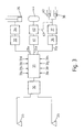
- FIG 3 there is shown a schematic block diagram of a control circuit for the apparatus shown in Figures 1 and 2.
- the ultrasonic transceivers 29 are shown coupled via a sensor interface 30 to a microprocessor 31.
- Microprocessor 31 includes a number of inputs 31a, 31b, etc, that are additional to the input from sensor interface 30.
- the additional inputs 31a, 31b, etc, relate to other control functions of the circuit.
- One output 31x of the microprocessor 31 is coupled via a lateral flotation interface 32 to a hydraulic control valve 34 for controlling a lateral flotation cylinder 35 acting between the header 10 and the straw elevator pivotally supporting the header in a lateral vertical plane on the harvesting machine in which the apparatus of the invention is incorporated.
- the position of cylinder 35 is controlled by means of the components of the circuit of Figure 3 in dependence on the differences in the distances measured by the respective ultrasonic sensors 29, i.e. in dependence on the differences in the heights of the header 10 above the ground sensed by the respective pivotable shoes 20a, 20b.
- a second output 31y of microprocessor 31 is coupled via a stubble height interface 36 to a hydraulic valve 37 controlling the header lifting cylinders 38, 40. These cylinders extend between the header 10 (in practice the elevator upon which the header 10 is mounted) and the vehicle chassis on either side of the elevator.
- the desired stubble height is inputted via one of the inputs 31a, 31b, etc to the microprocessor 31 and the absolute values of the signals from the ultrasonic sensors 29 are used for controlling the position of the header 10 above the ground surface 17.
- the ultrasonic sensors 29 are thus used for both the height control of the header and the lateral flotation of the header.
- a third output 31z of microprocessor 31 is coupled via a compensation interface 41 to a hydraulic valve 42 controlling both the header lifting cylinders 38, 40 (via control line 43) and a hydropneumatic accumulator 44, the function of which, in the compensation mode operation, is well known.
- the microprocessor 31 receives input signals on one of its inputs 31a, 31b, etc representative of the hydraulic pressure in the header lifting cylinders 38, 40 and, to this end, an oil pressure sensor is coupled to the hydraulic circuitry of the header lifting cylinders 38, 40.
- lateral adjustment of the header position is also accomplished in the manner as described above in connection with the operation in the 'lateral flotation' mode.
- the ultrasonic sensors 29 are not used in the 'compensation' mode for the compensation operation per se, they are nevertheless used, in this 'compensation mode' for accomplishing an additional lateral adjustment so as to take an eventual laterally inclined ground contour into account. This is advantageous to the extent that, on the one hand, the machine is subjected to less wear and tear and, on the other hand, a more even distribution of the header pressure on the ground surface is obtained.
- the microprocessor 31 may also be programmed for, in the 'compensation' mode, quickly lifting the header 10 in the event of the oil pressure sensor associated with the header lifting cylinders 38, 40 sensing a sudden and substantial drop in the hydraulic pressure. This is advantageous for avoiding the so-called 'bulldozing' of the header and/or the shoes 18, 20 digging into the ground when, in said 'compensation' mode, the header encounters a sudden and substantial rise in the ground surface, i.e. when the header encounters a substantial obstacle.
- Microprocessor 31 may include additional outputs for controlling other aspects of the operation of the header or of the vehicle in which it is installed. As an example, the microprocessor 31 may be programmed to automatically lift the header 10 when the combine harvester is driven in reverse.
- microprocessor 31 may function to control the operation of the header and the various ancillary components referred to in a variety of further ways that would be apparent to a worker skilled in the art.
- the inputs 31a, 31b, etc to the microprocessor 31 may include:
- the sensors 29 need not necessarily be of the ultrasonic type. It is desirable that the sensors 29 are of a 'contactless' type, preferably employing electromagnetic energy. However, numerous options may be employed and it is possible to conceive versions of the invention in which yet further kinds of sensors are employed.
- the invention may be employed in machinery other than agricultural harvesters.
- the apparatus of the invention is applicable in virtually any situation in which it is desired to control the spacing of eg. an implement relative to a surface.
- the invention is not limited to embodiments in which the pivotable shoes or their functional equivalents are moveable over the surface in question.
Landscapes
- Life Sciences & Earth Sciences (AREA)
- Environmental Sciences (AREA)
- Harvester Elements (AREA)
- Lifting Devices For Agricultural Implements (AREA)
- Control Of Position, Course, Altitude, Or Attitude Of Moving Bodies (AREA)
Claims (15)
- Vorrichtung zum Steuern der Position eines hinsichtlich seiner Position einstellbaren Gerätes (10) gegenüber einer Oberfläche (17), wobei die Vorrichtung folgendes umfasst:eine Sendeempfänger (29) zur Verwendung bei der Feststellung der Position des Gerätes (10) gegenüber der Oberfläche (17); wobei der Sendeempfänger (29) eine Signalquelle zum Aussenden von Signalen und einen Empfänger zum Empfang reflektierter Signale umfasst;ein Steuergerät (31), das zur Verwendung der Signale zur Steuerung von Stellgliedeinrichtungen (34, 35; 42, 44; 37, 38, 40) zur Einstellung der Position des Gerätes (10) gegenüber der Oberfläche (17) betreibbar ist; und dadurch gekennzeichnet, dass die Vorrichtung weiterhin folgendes umfasst:ein erstes Bauteil (20a, 20b), das beweglich an dem Gerät (10) befestigt ist und einen mit der Oberfläche in Eingriff kommenden Abschnitt (23) aufweist, um bei Berührung mit der Oberfläche (17) das erste Bauteil (20a, 20b) gegenüber dem Gerät (10) in Abhängigkeit von der Position des Gerätes (10) gegenüber der Oberfläche (17) einzustellen;ein weiteres Bauteil (24), das in Abhängigkeit von der Bewegung des ersten Bauteils (20a, 20b) beweglich ist; wobei das weitere Bauteil (24) einen Signalweiterleitungsabschnitt (26) entfernt von dem mit der Oberfläche in Eingriff kommenden Abschnitt (23) und in einer Entfernung von dem Sendeempfänger (29) einschließt; wobei die Signalquelle zur Aussendung von Signalen in Richtung auf den Signalweiterleitungsabschnitt (26) angeordnet ist; wobei der Empfänger zum Empfang von Signalen von der Oberfläche angeordnet ist, wie sie von dem Weiterleitungsabschnitt (26) reflektiert werden, und wobei das Steuergerät (31) betreibbar ist, um diese Signale zum Bewirken der Positionseinstellung zu verwenden.
- Vorrichtung nach Anspruch 1, dadurch gekennzeichnet, dass das erste Bauteil (20a, 20b) schwenkbar an dem Gerät (10) befestigt ist und das weitere Bauteil (24) starr an dem ersten Bauteil (20a, 20b) befestigt ist.
- Vorrichtung nach Anspruch 2, dadurch gekennzeichnet, dass das Gerät (10) von einem Fahrzeug getragen wird, das über die Oberfläche (17) beweglich ist; dass das erste Bauteil (20a, 20b) durch einen beweglichen Gleitschuh gebildet ist und dass der Signalweiterleitungsabschnitt (26) in Rückwärtsrichtung hinter dem Gerät (10) liegt, wenn sich das Fahrzeug in Vorwärtsrichtung über die Oberfläche (17) bewegt.
- Vorrichtung nach einem der vorhergehenden Ansprüche, dadurch gekennzeichnet, dass der Signalweiterleitungsabschnitt (26) einen reflektierenden Abschnitt in Form einer allgemein ebenen Oberfläche des weiteren Bauteils (24) oder einer an diesem befestigten Oberfläche einschließt.
- Vorrichtung nach einem der Ansprüche 1-3, dadurch gekennzeichnet, dass der Signalweiterleitungsabschnitt (26) einen reflektierenden Abschnitt in Form einer Oberfläche des weiteren Bauteils (24) oder einer daran befestigten Oberfläche einschließt, wobei die Oberfläche zumindest teilweise nicht-eben ist.
- Vorrichtung nach einem der vorhergehenden Ansprüche, dadurch gekennzeichnet, dass der Sendeempfänger (29) Schallsignale aussendet und empfängt.
- Vorrichtung nach einem der vorhergehenden Ansprüche, dadurch gekennzeichnet, das der Sendeempfänger (29) von dem Signalweiterleitungsabschnitt (26) durch einen Abstand im Bereich von 20-60 cm getrennt ist.
- Vorrichtung nach einem der vorhergehenden Ansprüche, dadurch gekennzeichnet, dass Einrichtungen zur Begrenzung der Bewegung des ersten Bauteils (20a, 20b) vorgesehen sind.
- Vorrichtung nach einem der vorhergehenden Ansprüche, dadurch gekennzeichnet, dass ein Riegel zur vorübergehenden Festlegung des ersten Bauteils (20a, 20b) gegen eine Bewegung vorgesehen ist.
- Vorrichtung nach einem der vorhergehenden Ansprüche, dadurch gekennzeichnet, dass zwei oder mehr erste Bauteile (20a, 20b) und eine entsprechende Anzahl von weiteren Bauteilen (24), Signalweiterleitungsabschnitten (26) und Sendeempfängern (29) vorgesehen sind.
- Vorrichtung nach Anspruch 10, dadurch gekennzeichnet, dass die ersten Bauteile (20a, 20b) in Betriebspaaren angeordnet sind, wobei eine Einstellung des Gerätes erfolgt, wenn die Bewegung beider Bauteile des Paares von dem Steuergerät (31) festgestellt wird.
- Fahrzeug, dadurch gekennzeichnet, dass es eine Vorrichtung nach einem der vorhergehenden Ansprüche beinhaltet.
- Fahrzeug nach Anspruch 12, dadurch gekennzeichnet, dass es als eine Erntemaschine ausgebildet ist, die ein Vorsatzgerät einschließt, wobei das Vorsatzgerät das Gerät (10) bildet.
- Fahrzeug nach Anspruch 13, dadurch gekennzeichnet, dass das Steuergerät (31) so konfiguriert ist, dass es selektiv das Vorsatzgerät (10) in Höheneinstell-, in lateralen Schwimm- und in Kompensations-Betriebsarten steuert.
- Fahrzeug nach Anspruch 13 oder 14, unter Rückbeziehung auf Anspruch 3, dadurch gekennzeichnet, dass ein oder mehrere feste Gleitschuhe (18) in das Vorsatzgerät (10) eingefügt sind und dass der bewegliche Gleitschuh 20a, 20b und der oder ein fester Gleitschuh 18 Seite an Seite in dem Vorsatzgerät (10) angeordnet sind.
Priority Applications (1)
| Application Number | Priority Date | Filing Date | Title |
|---|---|---|---|
| US08/717,385 US5713190A (en) | 1995-09-26 | 1996-09-20 | Apparatus for controlling a position-adjustable implement |
Applications Claiming Priority (2)
| Application Number | Priority Date | Filing Date | Title |
|---|---|---|---|
| GBGB9519565.7A GB9519565D0 (en) | 1995-09-26 | 1995-09-26 | Apparatus for controlling a position-adjustable implement |
| GB9519565 | 1995-09-26 |
Publications (2)
| Publication Number | Publication Date |
|---|---|
| EP0765594A1 EP0765594A1 (de) | 1997-04-02 |
| EP0765594B1 true EP0765594B1 (de) | 2003-05-28 |
Family
ID=10781254
Family Applications (1)
| Application Number | Title | Priority Date | Filing Date |
|---|---|---|---|
| EP96202420A Expired - Lifetime EP0765594B1 (de) | 1995-09-26 | 1996-08-30 | Vorrichtung zur Steuerung eines Gerätes, dessen Position einstellbar ist |
Country Status (4)
| Country | Link |
|---|---|
| US (1) | US5713190A (de) |
| EP (1) | EP0765594B1 (de) |
| DE (1) | DE69628386T2 (de) |
| GB (1) | GB9519565D0 (de) |
Families Citing this family (49)
| Publication number | Priority date | Publication date | Assignee | Title |
|---|---|---|---|---|
| DE19601420C2 (de) * | 1996-01-17 | 1999-10-14 | Deere & Co | Vorrichtung zum Führen eines Gerätes, insbesondere eines Erntebergungsvorsatzes, relativ zu einer von dem Gerät überfahrenen Oberfläche |
| CA2257049A1 (en) * | 1997-12-31 | 1999-06-30 | Richard Gramm | Combine header height control |
| GB9811177D0 (en) | 1998-05-26 | 1998-07-22 | Ford New Holland Nv | Methods for generating field maps |
| US6041583A (en) * | 1998-11-16 | 2000-03-28 | Deere & Company | Height sensing system for a harvester head |
| DE19853085B4 (de) * | 1998-11-18 | 2014-03-20 | Claas Selbstfahrende Erntemaschinen Gmbh | Verfahren zum Justieren einer an einer Feldmaschine befestigten Sensoreinheit sowie eine Justiereinrichtung und eine Feldmaschine |
| DE10011499A1 (de) | 2000-03-09 | 2001-09-20 | Case Harvesting Sys Gmbh | Vorrichtung zur Bodenkopierung für Vorsatzgeräte an Erntemaschinen |
| DE10011498B4 (de) | 2000-03-09 | 2004-12-30 | Case Harvesting Systems Gmbh | Vorrichtung zur Bodenkopierung für Vorsatzgeräte an Erntemaschinen |
| US6530197B1 (en) * | 2000-05-16 | 2003-03-11 | Deere & Company | Ground contact height sensor |
| DE10057135A1 (de) * | 2000-11-17 | 2002-05-23 | Deere & Co | Stelleinrichtung eines Aufnehmers für Erntegut |
| US6523333B2 (en) * | 2000-12-06 | 2003-02-25 | Leo A. Metzger | Sensor arm for combine header |
| DE20108319U1 (de) | 2001-05-17 | 2001-08-16 | Maschinenfabrik Bernard Krone GmbH, 48480 Spelle | Arbeitsaggregatekombination |
| GB2379429A (en) * | 2001-09-08 | 2003-03-12 | New Holland Uk Ltd | Tractor with lockable suspension |
| US6568161B1 (en) | 2001-11-15 | 2003-05-27 | New Holland North America, Inc. | User interface for a harvesting machine |
| CA2369862C (en) | 2002-01-31 | 2009-10-27 | Norbert Beaujot | Header height control apparatus |
| US20060185340A1 (en) * | 2003-05-19 | 2006-08-24 | Eyre Robert J | Cutting and threshing header for harvesting machine |
| US7310931B2 (en) * | 2003-08-05 | 2007-12-25 | Richard Gramm | Height sensor arrangement for agricultural applications |
| US6883299B1 (en) | 2003-08-05 | 2005-04-26 | Richard Gramm | Height sensor arrangement for agricultural applications |
| US7222474B2 (en) * | 2005-04-29 | 2007-05-29 | Cnh America Llc | Ground sensing apparatus for a header of an agricultural harvesting machine |
| US7430846B2 (en) * | 2005-05-10 | 2008-10-07 | Deere & Company | Floating header with integrated float system for use with an agricultural windrower or combine |
| US7222475B2 (en) * | 2005-05-10 | 2007-05-29 | Deere & Company | Header hydraulic float system |
| US7207164B2 (en) * | 2005-05-10 | 2007-04-24 | Deere & Company | Header hydraulic float suspension |
| US7191582B2 (en) * | 2005-05-10 | 2007-03-20 | Deere & Company | Header terrain following system |
| US7168229B1 (en) * | 2005-07-14 | 2007-01-30 | Cnh America Llc | Drop rate control for agricultural header |
| US7408450B2 (en) * | 2005-07-15 | 2008-08-05 | Cnh America Llc | Steering wheel direction indicator for neutral start |
| US7647753B2 (en) * | 2006-12-30 | 2010-01-19 | Headsight, Inc. | Header height control system and method |
| US7401455B1 (en) * | 2007-01-03 | 2008-07-22 | Cnh America Llc | System and method for controlling the base cutter height of a sugar cane harvester |
| FR2912871B1 (fr) * | 2007-02-28 | 2009-05-01 | Gyrax Soc Par Actions Simplifi | Machine de coupe de vegetaux,notamment broyeur-debroussailleur |
| FI119584B (fi) * | 2007-07-06 | 2009-01-15 | Actioneco Oy | Järjestely kasvillisuuden leikkaamiseen tarkoitetun leikkuulaitteen leikkuuvälineiden aseman säätämiseksi |
| US7730700B2 (en) * | 2008-09-30 | 2010-06-08 | Claas Selbstefahrende Erntemaschinen Gmbh | Header ground sensor |
| US8322242B2 (en) * | 2009-09-29 | 2012-12-04 | Hamilton Sundstrand Corporation | Velocity summing linear actuator |
| US7975458B1 (en) * | 2010-08-23 | 2011-07-12 | Cnh America Llc | Control system for a crop harvesting header |
| US20130061569A1 (en) * | 2010-11-03 | 2013-03-14 | Dean J. McClenathen | Device for flattening corn stalk stubbles |
| EP2797403B1 (de) * | 2011-12-28 | 2016-11-30 | Agco Corporation | Kufenblech für einen mähvorsatz mit flexibler schneideleiste |
| US9241440B2 (en) * | 2013-03-01 | 2016-01-26 | Cnh Industrial Canada Ltd. | Control system for a disc cutterbar using stubble cut quality feedback |
| US10531607B2 (en) * | 2013-07-31 | 2020-01-14 | Cnh Industrial America Llc | Header lateral tilt control with automatic operation in free float and controlled tilt modes |
| US20150195991A1 (en) * | 2014-01-15 | 2015-07-16 | Cnh America Llc | Header height control system for an agricultural harvester |
| US9861036B2 (en) | 2014-07-15 | 2018-01-09 | Cnh Industrial America Llc | Skid shoe for a header of an agricultural harvester |
| US9769986B2 (en) * | 2015-03-25 | 2017-09-26 | Deere & Company | Agricultural vehicle with automated repositioning system |
| DE102016002123B4 (de) * | 2016-02-24 | 2024-10-31 | Pöttinger Landtechnik Gmbh | Erntemaschine |
| US10517207B2 (en) * | 2016-05-02 | 2019-12-31 | Cnh Industrial America Llc | Programmable one-touch raise feature for an agricultural harvester such as a windrower |
| US10349578B2 (en) | 2017-02-16 | 2019-07-16 | Cnh Industrial America Llc | Combination flex and rigid header height control in a harvester |
| US10368488B2 (en) | 2017-09-18 | 2019-08-06 | Cnh Industrial America Llc | System and method for sensing harvested crop levels within an agricultural harvester |
| EP3456174B1 (de) * | 2017-09-18 | 2021-07-14 | CNH Industrial Belgium NV | Verfahren und system zur steuerung der höhe eines landwirtschaftlichen arbeitsgeräts in bezug auf den boden |
| AT522856B1 (de) * | 2019-06-27 | 2023-02-15 | Franz Schrattenecker | Schneidwerk für einen Mähdrescher |
| US11375654B2 (en) * | 2019-10-08 | 2022-07-05 | Deere & Company | Method and apparatus for adjusting a harvesting header float system based on machine pitch or terrain and system thereof |
| US12419220B2 (en) * | 2020-10-09 | 2025-09-23 | Deere & Company | Predictive map generation and control system |
| US11737390B2 (en) | 2021-02-23 | 2023-08-29 | Cnh Industrial America Llc | Harvesting header multi-sensor height control |
| DE102021119897A1 (de) * | 2021-07-30 | 2023-02-02 | Claas Selbstfahrende Erntemaschinen Gmbh | Landwirtschaftliche Maschine mit schwingungsgedämpftem Vorsatzgerät |
| US12484474B2 (en) * | 2023-01-09 | 2025-12-02 | Cnh Industrial America Llc | Breakaway rigid header height control system |
Family Cites Families (13)
| Publication number | Priority date | Publication date | Assignee | Title |
|---|---|---|---|---|
| US3722193A (en) * | 1971-10-21 | 1973-03-27 | Clayson Nv | Automatic header height controlling mechanism |
| GB1459684A (en) * | 1973-06-14 | 1976-12-22 | Clayson Nv | Agricultural machines |
| US4009555A (en) * | 1976-02-26 | 1977-03-01 | Massey-Ferguson Inc. | Height control for combine headers |
| US4414792A (en) * | 1982-03-30 | 1983-11-15 | Blackwelders | Height control for agricultural machine |
| DE3227975A1 (de) * | 1982-07-27 | 1984-02-09 | Claas Ohg, 4834 Harsewinkel | Selbstfahrender maehdrescher |
| US4573124A (en) * | 1984-01-09 | 1986-02-25 | Blackwelders | Height control for agricultural machine |
| DK293184A (da) * | 1984-06-15 | 1985-12-16 | Taarup As Maskinfab | Groenthoester |
| GB2173309B (en) * | 1985-04-02 | 1988-08-17 | Lundahl Inc Ezra C | Automatic sonar activated height control for a header |
| US4873817A (en) * | 1988-08-01 | 1989-10-17 | United Technologies Automotive, Inc. | Electrically controlled pressure relief valve system and method |
| JP2619025B2 (ja) * | 1988-11-29 | 1997-06-11 | 株式会社クボタ | コンバインの高さ制御装置 |
| US5155984A (en) * | 1991-04-24 | 1992-10-20 | Ford New Holland, Inc. | Implement height control |
| JPH0538222A (ja) * | 1991-08-07 | 1993-02-19 | Kubota Corp | コンバインの刈高制御装置 |
| DE4406892A1 (de) * | 1994-03-03 | 1995-09-07 | Bosch Gmbh Robert | Vorrichtung zur Regelung des Bodenabstandes einer Bearbeitungseinheit einer landwirtschaftlichen Maschine |
-
1995
- 1995-09-26 GB GBGB9519565.7A patent/GB9519565D0/en active Pending
-
1996
- 1996-08-30 DE DE69628386T patent/DE69628386T2/de not_active Expired - Lifetime
- 1996-08-30 EP EP96202420A patent/EP0765594B1/de not_active Expired - Lifetime
- 1996-09-20 US US08/717,385 patent/US5713190A/en not_active Expired - Lifetime
Also Published As
| Publication number | Publication date |
|---|---|
| EP0765594A1 (de) | 1997-04-02 |
| GB9519565D0 (en) | 1995-11-29 |
| US5713190A (en) | 1998-02-03 |
| DE69628386T2 (de) | 2003-11-27 |
| DE69628386D1 (de) | 2003-07-03 |
Similar Documents
| Publication | Publication Date | Title |
|---|---|---|
| US5713190A (en) | Apparatus for controlling a position-adjustable implement | |
| US8745964B2 (en) | Swather with float assembly and disconnect coupling | |
| CA2900067C (en) | Controlling cutting height and angle of a combine header | |
| US6826894B2 (en) | Position control for a crop pickup device | |
| US4414792A (en) | Height control for agricultural machine | |
| US5031705A (en) | Crop-sensing cultivator | |
| US7681382B2 (en) | Adjusting arrangement for the tongue of an agricultural baler | |
| HU218229B (hu) | Tapogatóberendezés önjáró aratógép önálló oldalvezetésére | |
| JP3541150B2 (ja) | 作業車の昇降制御装置 | |
| JP3583038B2 (ja) | 作業車の昇降制御装置 | |
| KR102840153B1 (ko) | 자동 위치조절 가능한 릴조립체를 구비한 콤바인 | |
| JP2855680B2 (ja) | コンバインの刈高制御装置 | |
| WO1996001554A1 (en) | Flotation control system | |
| JPH0224414Y2 (de) | ||
| JPS6137216Y2 (de) | ||
| SU1540708A1 (ru) | Копирующее устройство срезающего аппарата капустоуборочной машины | |
| JPH0528982Y2 (de) | ||
| WO2025171477A1 (en) | Method for controlling reel height | |
| JP3664603B2 (ja) | 刈取収穫機 | |
| JPH0525387Y2 (de) | ||
| JPS61199714A (ja) | 収穫機の刈高さ自動調節装置 | |
| JPH0767429A (ja) | 作業車の対地高さ検出装置 |
Legal Events
| Date | Code | Title | Description |
|---|---|---|---|
| PUAI | Public reference made under article 153(3) epc to a published international application that has entered the european phase |
Free format text: ORIGINAL CODE: 0009012 |
|
| AK | Designated contracting states |
Kind code of ref document: A1 Designated state(s): DE FR GB IT |
|
| 17P | Request for examination filed |
Effective date: 19970926 |
|
| GRAH | Despatch of communication of intention to grant a patent |
Free format text: ORIGINAL CODE: EPIDOS IGRA |
|
| RAP1 | Party data changed (applicant data changed or rights of an application transferred) |
Owner name: CNH BELGIUM N.V. |
|
| GRAH | Despatch of communication of intention to grant a patent |
Free format text: ORIGINAL CODE: EPIDOS IGRA |
|
| GRAA | (expected) grant |
Free format text: ORIGINAL CODE: 0009210 |
|
| AK | Designated contracting states |
Designated state(s): DE FR GB IT |
|
| REG | Reference to a national code |
Ref country code: GB Ref legal event code: FG4D |
|
| REF | Corresponds to: |
Ref document number: 69628386 Country of ref document: DE Date of ref document: 20030703 Kind code of ref document: P |
|
| ET | Fr: translation filed | ||
| PLBE | No opposition filed within time limit |
Free format text: ORIGINAL CODE: 0009261 |
|
| STAA | Information on the status of an ep patent application or granted ep patent |
Free format text: STATUS: NO OPPOSITION FILED WITHIN TIME LIMIT |
|
| 26N | No opposition filed |
Effective date: 20040302 |
|
| REG | Reference to a national code |
Ref country code: DE Ref legal event code: R082 Ref document number: 69628386 Country of ref document: DE Representative=s name: PATENTANWAELTE WALLACH, KOCH & PARTNER, DE |
|
| REG | Reference to a national code |
Ref country code: DE Ref legal event code: R082 Ref document number: 69628386 Country of ref document: DE Representative=s name: PATENTANWAELTE WALLACH, KOCH, DR. HAIBACH, FEL, DE Effective date: 20140428 Ref country code: DE Ref legal event code: R082 Ref document number: 69628386 Country of ref document: DE Representative=s name: PATENTANWAELTE WALLACH, KOCH & PARTNER, DE Effective date: 20140428 Ref country code: DE Ref legal event code: R081 Ref document number: 69628386 Country of ref document: DE Owner name: CNH INDUSTRIAL BELGIUM NV, BE Free format text: FORMER OWNER: CNH BELGIUM NV, ZEDELGEM, BE Effective date: 20140428 |
|
| REG | Reference to a national code |
Ref country code: FR Ref legal event code: CD Owner name: CNH INDUSTRIAL BELGIUM NV Effective date: 20140725 |
|
| PGFP | Annual fee paid to national office [announced via postgrant information from national office to epo] |
Ref country code: DE Payment date: 20140715 Year of fee payment: 19 |
|
| PGFP | Annual fee paid to national office [announced via postgrant information from national office to epo] |
Ref country code: FR Payment date: 20140710 Year of fee payment: 19 Ref country code: GB Payment date: 20140714 Year of fee payment: 19 |
|
| PGFP | Annual fee paid to national office [announced via postgrant information from national office to epo] |
Ref country code: IT Payment date: 20140819 Year of fee payment: 19 |
|
| REG | Reference to a national code |
Ref country code: DE Ref legal event code: R119 Ref document number: 69628386 Country of ref document: DE |
|
| GBPC | Gb: european patent ceased through non-payment of renewal fee |
Effective date: 20150830 |
|
| PG25 | Lapsed in a contracting state [announced via postgrant information from national office to epo] |
Ref country code: IT Free format text: LAPSE BECAUSE OF NON-PAYMENT OF DUE FEES Effective date: 20150830 |
|
| REG | Reference to a national code |
Ref country code: FR Ref legal event code: ST Effective date: 20160429 |
|
| PG25 | Lapsed in a contracting state [announced via postgrant information from national office to epo] |
Ref country code: DE Free format text: LAPSE BECAUSE OF NON-PAYMENT OF DUE FEES Effective date: 20160301 Ref country code: GB Free format text: LAPSE BECAUSE OF NON-PAYMENT OF DUE FEES Effective date: 20150830 |
|
| PG25 | Lapsed in a contracting state [announced via postgrant information from national office to epo] |
Ref country code: FR Free format text: LAPSE BECAUSE OF NON-PAYMENT OF DUE FEES Effective date: 20150831 |