EP0765284B1 - Package for media disc and label assembly therefor - Google Patents
Package for media disc and label assembly therefor Download PDFInfo
- Publication number
- EP0765284B1 EP0765284B1 EP95924597A EP95924597A EP0765284B1 EP 0765284 B1 EP0765284 B1 EP 0765284B1 EP 95924597 A EP95924597 A EP 95924597A EP 95924597 A EP95924597 A EP 95924597A EP 0765284 B1 EP0765284 B1 EP 0765284B1
- Authority
- EP
- European Patent Office
- Prior art keywords
- sleeve
- label assembly
- disc
- identification information
- package
- Prior art date
- Legal status (The legal status is an assumption and is not a legal conclusion. Google has not performed a legal analysis and makes no representation as to the accuracy of the status listed.)
- Expired - Lifetime
Links
Images


Classifications
-
- G—PHYSICS
- G09—EDUCATION; CRYPTOGRAPHY; DISPLAY; ADVERTISING; SEALS
- G09F—DISPLAYING; ADVERTISING; SIGNS; LABELS OR NAME-PLATES; SEALS
- G09F3/00—Labels, tag tickets, or similar identification or indication means; Seals; Postage or like stamps
- G09F3/02—Forms or constructions
-
- B—PERFORMING OPERATIONS; TRANSPORTING
- B65—CONVEYING; PACKING; STORING; HANDLING THIN OR FILAMENTARY MATERIAL
- B65D—CONTAINERS FOR STORAGE OR TRANSPORT OF ARTICLES OR MATERIALS, e.g. BAGS, BARRELS, BOTTLES, BOXES, CANS, CARTONS, CRATES, DRUMS, JARS, TANKS, HOPPERS, FORWARDING CONTAINERS; ACCESSORIES, CLOSURES, OR FITTINGS THEREFOR; PACKAGING ELEMENTS; PACKAGES
- B65D65/00—Wrappers or flexible covers; Packaging materials of special type or form
- B65D65/38—Packaging materials of special type or form
- B65D65/42—Applications of coated or impregnated materials
-
- B—PERFORMING OPERATIONS; TRANSPORTING
- B65—CONVEYING; PACKING; STORING; HANDLING THIN OR FILAMENTARY MATERIAL
- B65D—CONTAINERS FOR STORAGE OR TRANSPORT OF ARTICLES OR MATERIALS, e.g. BAGS, BARRELS, BOTTLES, BOXES, CANS, CARTONS, CRATES, DRUMS, JARS, TANKS, HOPPERS, FORWARDING CONTAINERS; ACCESSORIES, CLOSURES, OR FITTINGS THEREFOR; PACKAGING ELEMENTS; PACKAGES
- B65D85/00—Containers, packaging elements or packages, specially adapted for particular articles or materials
- B65D85/54—Containers, packaging elements or packages, specially adapted for particular articles or materials for articles of special shape not otherwise provided for
- B65D85/544—Containers, packaging elements or packages, specially adapted for particular articles or materials for articles of special shape not otherwise provided for for gramophone records
- B65D85/546—Containers, packaging elements or packages, specially adapted for particular articles or materials for articles of special shape not otherwise provided for for gramophone records formed by folding a single blank
Definitions
- the present invention relates to packaging for storage media discs and method for making the same, and, more particularly, relates to a package sleeve or jacket in which audio or ROM compact discs may be safely contained as a more economical means of containing/shipping these components in comparison to the standard styrene jewel boxes.
- the invention also relates to a label assembly for that package sleeve.
- the jewel box is usually made of transparent plastic and is rectangular in shape.
- Many such jewel boxes include three distinct components: a rectangular base tray, a corresponding rectangular cover and a mounting hub.
- the base tray and cover are pivotally connected at their base corners to form a clam shell-like enclosure, and the mounting hub is inserted into the base tray.
- the standard jewel box design has been found to be relatively expensive to manufacture as it requires substantial raw material expenditures. More specifically, the relatively expensive transparent plastic must be suitably formed into the three basic components of the standard jewel box.
- the interior surface of the base tray may include arched ribs which extend upwardly and surround the disc in a manner such that the cover is prevented from touching the disc.
- the location of the ribs makes them ineffective to protect the disc when a cover breaks as a result of force applied to it.
- the jewel box due to its fragile nature is not suited for individual distribution without additional protection as if the jewel case becomes damaged, even if the disc is not, the complete package may be considered a defect by the customer. It is therefore desirable to provide a storage container for compact discs which has interior surfaces and edges which will not scratch or otherwise damage the disc and which is more immune to incidental contact allowing the package to accept rough handling without failure.
- the CD-ROM compact disc does not require a relatively expensive jewel case for final use since the user inserts the disc into a special CD-ROM drive caddy eliminating the need for a redundant storage unit. Further, the weight of the jewel box and its associated paper products lead to increased shipping costs. Thus, it has been found desirable to provide a more economical method for packaging CD-ROM discs which alleviates the additional costs in the form of materials, handling and shipping associated with the existing packaging method (i.e., the styrene jewel box).
- US - A - 5318222 discloses a mailer for disks. The mailer has first and second pockets for receiving disks, each pocket formed of front and back rectangular panel members joined at at least one pair of corresponding edges and unconnected on at least one pair of corresponding edges.
- the pockets are foldably attached by a spine at an edge of each of said pockets.
- the disk is retained in the pocket by retaining means.
- the sealing member is provided on a flap which is integral with a front panel of the mailer.
- the flap has adhesive which attaches the flap to a rear panel of the mailer.
- the flap has a tear strip which in use overlies the rear panel.
- a package sleeve and label assembly comprising a package sleeve including a sleeve cavity for accommodating a storage media disc therein and having a front portion and a back portion opposed to said front portion, and a label assembly adhesively applied to said package sleeve so as to form in cooperation with said package sleeve a mailable sleeve assembly, said label assembly comprising a unitary structure formed of a combination of a removable tear strip, a first face including mailing identification information means for identifying mailing information regarding the package sleeve and a second face including product identification information means for providing product identifying information regarding the storage media disc accommodated within the package sleeve wherein said first face and said second face are provided on opposite sides of said tear strip, said tear strip providing a closure flap for the sleeve cavity so as to retain disc in the sleeve cavity and upon removal thereof from the label assembly, the disc can be easily removed from and re-inserted into the
- the interior surfaces and edges of the package sleeve will not scratch or otherwise damage the disc when it is contained in the sleeve cavity as portions of the first and second folded-over double panels facing the sleeve cavity are treated with a coating to provide scracth resistance.
- this coating is an aqueous-based acrylic clear coating.
- Another aspect of the invention provides a method of sealing a package sleeve having a front portion and a back portion and which accommodates information media within a sleeve cavity provided between the front and rear faces, said method comprising the steps of sealing the sleeve cavity with an adhesive label assembly so as to form in cooperation with said package sleeve a mailable sleeve assembly with said label assembly comprising a unitary structure formed of a combination of a removable tear strip, mailing identification information means for identifying mailing information regarding the package sleeve and product identification information means for product identifying information regarding the information media accommodated within the package sleeve, wherein said mailing identification means and said product identification means are provided on opposite sides of said tear strip, said tear strip providing a closure flap for the sleeve cavity so as to retain the information media in the sleeve cavity, and adhesively applying said mailing identification information means provided on said label assembly to said front portion of said package sleeve and adhesively applying said product identification information means provided on said label assembly
- a further aspect of the invention provides a method for making a package sleeve for accommodating information media therein from a carton blank comprising a front portion, first and second side flap portions connected to said front portion along respective first and second bend lines, a back portion connected to said front portion along a third bend line, and top and bottom outer flap portions connected respectively to said front portion and to said back portion along respective fourth and fifth bend lines and for sealing the package sleeve, said method comprising the steps of: (a) folding said top outer flap portion along said fourth bend line; (b) adhesively attaching said top outer flap portion to said front portion; (c) folding said bottom outer flap portion along said fifth bend line; (d) adhesively attaching said bottom outer flap portion to said back portion; (e) folding said back portion and said bottom outer flap portion adhered thereto along said third bend line; (f) folding said first and second side flap portions along respectively said first and second bend lines, respectively; (g) adhesively attaching said first and second side flap portions to said back portion to thereby form a slee
- a label assembly for a package sleeve including a sleeve cavity for accommodating a storage media disc
- This label assembly includes a tear strip covering the sleeve cavity such that when the tear strip is detached along perforation lines provided in the label assembly, the disc can be removed from the sleeve cavity.
- the tear strip also includes a deadened adhesive portion facing the sleeve cavity so that no adhesive can contact the disc.
- the label assembly also includes a first face and a second face positioned on opposite sides of the tear strip with both the first and second faces having an adhesive backing.
- the first face of the label assembly includes mailing identification information such as the mailing address, return address, postal idicia and postal bar code, etc.
- the first face of the label assembly including this mailing identification information is adhesively applied to the front portion of the package sleeve.
- the second face of the label assembly includes product identification information regarding the storage media disc accommodated within the package sleeve.
- this product identification information can include text information regarding the disc accommodated in the package sleeve as well as a product identification bar code regarding the particular disc.
- an address verification bar code can be provided on the second face referencing the specific mailing identification on the first face of the label will be included for use with an address verification system.
- the second face of the label assembly is adhesively applied to the back portion of the package sleeve.
- Figure 1 a carton blank 10 for forming a package sleeve for containing storage media discs in accordance with the teachings of the present invention is illustrated. More specifically, Figure 1 illustrates one side of the carton blank and Figure 2 illustrates the opposite side thereof.
- the blank includes a front panel 12 and a back panel 14 connected to the front panel 12 along fold line 15.
- the front panel 12 is comprised of a front portion 16 and a first outer flap portion 18 connected to the front portion 16 along bend line 21.
- the back panel 14 of the blank is comprised of a back portion 20 and a second outer flap portion 22 connected to the back portion 20 along bend line 24.
- Two side flap portions 26 and 28 are respectively connected to the front portion 16 along bend lines 30 and 32.
- front panel 12, back panel 14, front portion 16, outer flap portions 18 and 22, back portion 20 and side flap portions 26 and 28 shown on the side of Figure 1 have also been designated as 12a, 14a, 16a, 18a, 20a, 22a, 26a and 28a whereas those features on the other side of Figure 2 have been designated as 12b, 14b, 16b, 18b, 20b, 22b, 26b and 28b.
- the carton blank 10 has the following properties: Basis Weight, lbs/3,000 Sq. Ft. 172 gam 279.9 Caliper, .001 inch 14.0 mm 0.356 Stiffness, Taber MD 132 CD 65 mNm MD 12.95 CD 6.38 Brightness, % CS 83.0 UCS 82.5 Moisture, % 5.8 Gloss, % CS 57 Smoothness CS 29 (Sheffield Units) UCS 185
- Such a carton material with the above properties is currently available from International Paper Corporation, Bleached Board Division having the Grade Code 1220, under the tradename Everest which can be described as 14 pnt, SBS, C1S, 0.014", solid bleached sulfite, coated one side.
- the process for making the package sleeve of the present invention is illustrated in Figures 3 through 6.
- the first outer flap portion 18 is folded along fold line 21 in the direction of arrow A as shown in Figure 3 such that the glue area 34 provided on the side 18b of outer flap portion 18 is adhesively attached to the side 16b of front portion 16.
- the second outer flap portion 22 is folded along fold line 24 in the direction of arrow B such that the glue area 36 provided on the side 22b of outer flap portion 22 is adhesively attached to the side 20b of back portion 20.
- the back portion 20 with the outer flap portion 22 adhered thereto are then folded along fold line 15 in the direction of arrow C (see Fig. 5) such that the outer flap portion 22 is aligned with the outer flap portion 18.
- the two side flap portions 26 and 28 are respectively folded along fold lines 30 and 32 in the direction of arrows D and E in Figure 6 such that the glue areas 38 and 40 provided on the respective sides 26b and 28b of the flap portions are adhesively attached to the rear portion 20.
- a sleeve cavity 42 is formed between outer flap portions 18 and 22 for containment of a storage media disc therein.
- the entire folded blank is then pressed flat.
- the package sleeve can then be covered with shrink wrap to seal the open end of the sleeve cavity 42.
- a package sleeve for accommodating storage media disk having a front panel 12 and a back panel 14 connected thereto along fold line 15 with the two side flap panels 26 and 28 connected to the front panel 12.
- the front panel 12 is in the form of a first folded-over double panel including the outer flap portion 18 and the front portion 16 and the back panel 14 is in the form of a second folded-over double panel including the outer flap portion 22 and the back portion 20.
- the two side flap portions 26 and 28 are adhesively attached to the back panel 14 to form the sleeve cavity 42 between the outer flap portion sides 18b and 22b for containment of the storage disc media therein.
- the side flap portions 26 and 28 have generally rounded corners, such as 46 and 48 (see Fig. 8). This corner design retards wear of the side flap portions which would be enhanced if sharp corners were present. These rounded corners also provide a generally cleaner appearance to the finished package sleeve.
- the carton blank 10 of Figures 1 and 2 has also been specifically designed to accommodate a storage media disc (i.e., compact or ROM compact disc) having a diameter no greater than 12cm.
- the overall blank 10 has a dimension of approximately 19 3/4" in length and 6 5/8" in width.
- the front portion 16 has a dimension of approximately 5" in length and 5 1/8" in width whereas the back portion 20 has a dimension of approximately 5" in length and 4 15/16" in width.
- the outer flap portions 18 and 22 both have dimensions of approximately 4 7/8" in length and 4 15/16" in width.
- the fold lines are preferably 1/16" wide.
- the paper stock grain direction of the blank is along the length thereof.
- the package sleeve of the present invention can be turned open side down and shaken without the disc becoming dislodged.
- the only way to remove the disc from the sleeve is to apply light pressure to the sides of the sleeve in order to make the sleeve cavity "pucker.” Without this external pressure on the sleeve the disc remains gently held in place by the extreme outer edge non-program area of the disc.
- the package sleeve of the present invention also has printed areas 44 on one side of the front portion 16, back portion 20 and side flap portion 26 and 28 of the blank 10 (See Figure 1) to provide printed information, such as information about the musical recordings, the artists and other such promotional materials, for the CD or ROM compact disc contained within the package sleeve. After the folding process, the printed areas 44 appear on the exterior surface of the package sleeve (see Figures 7 and 8) for visual display to the purchaser.
- the side of the package sleeve containing the printed area (i.e., the side of the carton blank 10 shown in Figure 1) is treated with a coating to provide scratch resistance for the storage media disc.
- This coating is preferably an aqueous-based acrylic clear coating.
- aqueous-based acrylic clear coating is manufactured by Algan, Inc. under the trade designation Algloss Overcoating 3048.
- This coating typically has the following physical properties: Viscosity : 30-35 seconds, #3 Zahn cup @ 70°F pH : 8.0-9.0 Non-Volatiles : 40-42% VOC : 1.4 lbs/gallon minus water Weight/Gallon : 8.5-8.7 lbs Freeze/Thaw : Stability
- Viscosity 30-35 seconds, #3 Zahn cup @ 70°F pH : 8.0-9.0
- VOC 1.4 lbs/gallon minus water Weight/Gallon : 8.5-8.7 lbs Freeze/Thaw : Stability
- the outer flap portion sides 18a and 22a which face into the sleeve cavity 42 in the finished package sleeve (see Figures 7 and 8) will be so coated.
- the interior surfaces and edges of this package sleeve will not scratch of otherwise damage the audio or ROM compact disc when it is contained in the sleeve cavity 42.
- the package sleeve of the present invention does not require the additional paper products for the back lines and the booklet of the jewel box as the associated identification and graphics are printed directly to the external point surfaces of the sleeve. This minimizes the chances for mixed orders in comparison to the jewel box design. Additionally, the package sleeve of the present invention is of a reduced weight as compared to the jewel box design. The package sleeve of the present invention is thus a more economical alternative for packaging compact discs (audio or ROM) in comparison to the standard styrene jewel case. It offers both a reduction in material and shipping/storage costs.
- this chipboard package sleeve offers complete protection during handling/shipping of both audio and ROM compact discs as interior surfaces and edges of the sleeve that the disc come in contact are treated with a coating such that they will not damage the disc.
- this package sleeve is readily adaptable to automated assembly processes.
- the package sleeve of the present invention with its uniform [thickness] cross section thickness resulting from a uniform sleeve cavity or pocket using full-sized panels and external gluing flaps allows the sleeve to stack without leaning profusely as will occur if the sleeve had thickness differences. This stacking uniformity allows more empty sleeves to be stored in a feed magazine with respect to automated inserting of discs into sleeves which is important for efficiency and throughput.
- the package sleeve of the present invention also provides protection to the disc but is more immune to incidental contact than the jewel box allowing the package to accept rough handling without damage or defect.
- the label assembly 50 of the present invention has an overall dimension of approximately 4 7/8" in width and 3 1/2" in length and includes three sections: namely; a tear strip 52 and respective first and second faces or parts 54 and 56 provided on opposite sides of the tear strip 52.
- the first and second faces 54 and 56 have respective adhesive backings 70 and 72 (see Fig. 10).
- the tear strip 52 when applied to the package sleeve 10, the tear strip 52 covers the sleeve cavity 42 so that the storage media disc accommodated within the sleeve cavity will be sealed therein until ready for use.
- the tear strip 52 includes a pair of perforation lines 58 and 60 such that when it is desirable to remove the disc from the sleeve cavity 42, a pull tab 62 provided on the tear strip 52 is lifted and the tear strip is detached along the perforation lines 58 and 60.
- the tear strip 52 is approximately 1/2" in length and the pull tab 62 extends approximately 3/16" in width from the width of the first and second faces 54 and 56 of the label assembly.
- the tear strip 52 of the label assembly 50 of the present invention not only seals the open end of the sleeve cavity 42 but is also designed such that it will not scratch or place adhesive on the disc.
- the tear strip 52 includes a deadened adhesive portion 63 covering and facing the open end of the sleeve cavity to assure that no adhesive can contact the disc (see Fig. 10).
- the tear strip width is preferably approximately 0.5" so that this label assembly cannot only be used with a package sleeve accommodating a single storage media disc but also be used with package sleeves accommodating double, triple, quad, etc. storage media discs. This label assembly could then be utilized to close multiple single disc package sleeves that are glued together.
- the first face 54 of the label assembly 50 includes identifying mailing information 64 printed thereon for shipping (see Fig. 9).
- This identifying mailing information 64 can include information such as the mailing address 65 of the recipient of the package sleeve, the return address of the sender, postal indicia 67 and a postal bar code.
- the first face 54 is approximately 2 1/2" in length.
- the second face 56 includes product identification information 66 regarding the particular disc accommodated within the package sleeve or a product identification bar code regarding the disc.
- an address verification bar code 70 can be included on the second face 56 which references the specific mailing information 64 on the first face 54 of label assembly 50 which is to be used by an address verification system.
- this product identification information 66 can include text information 68 regarding the disc accommodated within the package sleeve and a product identification bar code (not shown) regarding the disc.
- this product identification information assists in tracking the disc in inventory as well as providing additional consumer information regarding the disc.
- the second face 56 is approximately 1/2" in length.
- the label material is vinyl for strength (preferably, Walace #401 Kimdura synthetic vinyl), glossy white for appearance and has a permanent adhesive for security.
- the label material is also print and apply compatible.
- the identifying mailing information 64 and product identification information 66 can be printed onto the label assembly immediately before the label assembly is applied to the package sleeve.
- the present invention also relates to a method for sealing a package sleeve.
- the sleeve cavity 42 of the package sleeve is covered with the removable tear strip 52 to reliably seal the sleeve cavity and retain the storage media disc within the sleeve cavity.
- the strip 52 covers the sleeve cavity
- the deadened adhesive portion 63 of the tear strip 52 faces the sleeve cavity so that no adhesive can contact the disc accommodated within the sleeve cavity.
- the pull tab 62 is lifted upwardly such that the tear strip 52 is detached along perforation lines 58 and 60 to thereby open the sleeve cavity.
- the present invention further relates to a method for providing mailing information and product identification information regarding the package sleeve and disc accommodated therein.
- the first and second faces 54 and 56 of the label assembly are folded inwardly along the perforation lines 58 and 60.
- the adhesive backing 70 of the first face 54 is then adhesively attached to the front portion 16a (see Figs. 7 and 11) of the package sleeve.
- the mailing identification information 64 of the first face 54 is attached to the front portion 16a.
- the adhesive backing 72 of the second face 56 is adhesively attached to the rear portion 20a (see Figs. 8 and 12) of the package sleeve.
- the product identification information 66 of the second face 56 is attached to back portion 20a.
- the mailing identification information 64 and the product identification information 66 are exposed and therefore the information contained thereon can be visually read and/or scanned with a bar code reader.
- the label assembly 50 of the present invention can be automated using a one step process. Speeds can be approximately 60 parts per minute with each part having a 0.4-0.5 second dwell. Physically, the automation cell can be less than approximately 4 feet in length.
- FIG. 13 This one-step automated process is shown in Figure 13.
- the label assembly 50 is fed out of a printer (not shown) onto a tamp block 80 supported by a pair of guide rods 82a and 82b.
- the package sleeve is in a staged position between a pair of spring loaded rollers 84a and 84b of the tamp block 80.
- a tamp cylinder 86 Upon actuation of a tamp cylinder 86, the tamp block 80 is moved in generally the direction of arrow f such that the spring loaded rollers 84a and 84b impart a force respectively to the first face 54 and second face 56 of the label assembly to move the faces 54 and 56 inwardly toward the package sleeve in the direction of arrow g.
- the faces 54 and 56 are moved by the rollers 82a and 82b until the first face 54 is attached to the front face 16a of the package sleeve and the second face 56 is attached to the rear face 20a of the package sleeve by means of the adhesive backings 70 and 72.
- the first and second faces 54 and 56 of the label assembly are then smoothed over the package sleeve by the rotational force applied by the rollers 82a and 82b.
- the label assembly of the present invention when applied to a package sleeve forms a secure package by which a single CD-ROM can be mailed.
- the pull tab is lifted and the deadened tear strip is removed to open the sleeve.
- the disc accommodated in the sleeve cavity can then be removed without damage.
- the label assembly is further designed so that all necessary mailing information is printed on the label just before it is automatically applied.
- the label assembly of the present invention is a cost effective means to distribute a single title to multiple address locations.
- the combination package sleeve/label assembly is economical to mail due to its reduced size and weight.
- an identifying bar code can be printed on the back of each label assembly so that a bar code reader can scan each printed label after application.
- a data base can then compare "Finished Work" to "Requested Work” with any discrepancies noted.
- This closed loop address verification can be extended to a serialized CD-ROM with an identifying bar code sticker which can also be scanned with a bar code reader.
- This additional information can also be written to the "Finished Work" data base.
- a report can then be generated to show the exact address location of the particular package sleeve.
Abstract
Description
- The present invention relates to packaging for storage media discs and method for making the same, and, more particularly, relates to a package sleeve or jacket in which audio or ROM compact discs may be safely contained as a more economical means of containing/shipping these components in comparison to the standard styrene jewel boxes. The invention also relates to a label assembly for that package sleeve.
- Storage containers for a standard compact disc or the like are often called "jewel boxes." The jewel box is usually made of transparent plastic and is rectangular in shape. Many such jewel boxes include three distinct components: a rectangular base tray, a corresponding rectangular cover and a mounting hub. Usually, the base tray and cover are pivotally connected at their base corners to form a clam shell-like enclosure, and the mounting hub is inserted into the base tray.
- With increasing demands of the consumer to keep the cost of compact discs as low as possible, the standard jewel box design has been found to be relatively expensive to manufacture as it requires substantial raw material expenditures. More specifically, the relatively expensive transparent plastic must be suitably formed into the three basic components of the standard jewel box.
- In utilizing the typical styrene jewel boxes, automated assembly processes are relatively expensive and time consuming. The increased cost of production occurs because the tabs and/or protruding sidewalls adjacent to the recessed bottoms of the surface of the base tray often get caught in the automated equipment, which, in turn, can lead to mixed orders. In addition, difficulties with the jewel box assembly occur from the need to include two paper products; namely: the back liner and the booklet. These additional paper products are required to add identification and graphics to the clear jewel box. For these reasons, the insert cards and discs are often inserted by hand or extra maintenance for the machine must be expended to keep the production line up and running.
- Further, in the typical styrene jewel box, the interior surface of the base tray may include arched ribs which extend upwardly and surround the disc in a manner such that the cover is prevented from touching the disc. However, the location of the ribs makes them ineffective to protect the disc when a cover breaks as a result of force applied to it. Moreover, the jewel box due to its fragile nature is not suited for individual distribution without additional protection as if the jewel case becomes damaged, even if the disc is not, the complete package may be considered a defect by the customer. It is therefore desirable to provide a storage container for compact discs which has interior surfaces and edges which will not scratch or otherwise damage the disc and which is more immune to incidental contact allowing the package to accept rough handling without failure.
- Moreover, the CD-ROM compact disc does not require a relatively expensive jewel case for final use since the user inserts the disc into a special CD-ROM drive caddy eliminating the need for a redundant storage unit. Further, the weight of the jewel box and its associated paper products lead to increased shipping costs. Thus, it has been found desirable to provide a more economical method for packaging CD-ROM discs which alleviates the additional costs in the form of materials, handling and shipping associated with the existing packaging method (i.e., the styrene jewel box). US - A - 5318222 discloses a mailer for disks. The mailer has first and second pockets for receiving disks, each pocket formed of front and back rectangular panel members joined at at least one pair of corresponding edges and unconnected on at least one pair of corresponding edges. The pockets are foldably attached by a spine at an edge of each of said pockets. There is a sealing member for adhering the first pocket to the second pocket to maintain the mailer in a closed conformation. At any pocket edge not retaining the received disk by the joined edges, the spine, or the sealing member, the disk is retained in the pocket by retaining means.
- The sealing member is provided on a flap which is integral with a front panel of the mailer. The flap has adhesive which attaches the flap to a rear panel of the mailer. The flap has a tear strip which in use overlies the rear panel.
- According to one aspect of the present invention, there is provided a package sleeve and label assembly comprising a package sleeve including a sleeve cavity for accommodating a storage media disc therein and having a front portion and a back portion opposed to said front portion, and a label assembly adhesively applied to said package sleeve so as to form in cooperation with said package sleeve a mailable sleeve assembly, said label assembly comprising a unitary structure formed of a combination of a removable tear strip, a first face including mailing identification information means for identifying mailing information regarding the package sleeve and a second face including product identification information means for providing product identifying information regarding the storage media disc accommodated within the package sleeve wherein said first face and said second face are provided on opposite sides of said tear strip, said tear strip providing a closure flap for the sleeve cavity so as to retain disc in the sleeve cavity and upon removal thereof from the label assembly, the disc can be easily removed from and re-inserted into the sleeve cavity and said first face remains applied to said front portion and said second face remains applied to said back portion.
- In accordance with an embodiment of the present invention, the interior surfaces and edges of the package sleeve will not scratch or otherwise damage the disc when it is contained in the sleeve cavity as portions of the first and second folded-over double panels facing the sleeve cavity are treated with a coating to provide scracth resistance. In the preferred embodiment, this coating is an aqueous-based acrylic clear coating.
- Another aspect of the invention provides a method of sealing a package sleeve having a front portion and a back portion and which accommodates information media within a sleeve cavity provided between the front and rear faces, said method comprising the steps of sealing the sleeve cavity with an adhesive label assembly so as to form in cooperation with said package sleeve a mailable sleeve assembly with said label assembly comprising a unitary structure formed of a combination of a removable tear strip, mailing identification information means for identifying mailing information regarding the package sleeve and product identification information means for product identifying information regarding the information media accommodated within the package sleeve, wherein said mailing identification means and said product identification means are provided on opposite sides of said tear strip, said tear strip providing a closure flap for the sleeve cavity so as to retain the information media in the sleeve cavity, and adhesively applying said mailing identification information means provided on said label assembly to said front portion of said package sleeve and adhesively applying said product identification information means provided on said label assembly to said back portion of said package sleeve, said tearstrip being detachable from said label assembly along perforation lines provided in said label assembly to enable removal of the information media from the sleeve cavity and reinsertion of the information media into the sleeve cavity.
- A further aspect of the invention provides a method for making a package sleeve for accommodating information media therein from a carton blank comprising a front portion, first and second side flap portions connected to said front portion along respective first and second bend lines, a back portion connected to said front portion along a third bend line, and top and bottom outer flap portions connected respectively to said front portion and to said back portion along respective fourth and fifth bend lines and for sealing the package sleeve, said method comprising the steps of: (a) folding said top outer flap portion along said fourth bend line; (b) adhesively attaching said top outer flap portion to said front portion; (c) folding said bottom outer flap portion along said fifth bend line; (d) adhesively attaching said bottom outer flap portion to said back portion; (e) folding said back portion and said bottom outer flap portion adhered thereto along said third bend line; (f) folding said first and second side flap portions along respectively said first and second bend lines, respectively; (g) adhesively attaching said first and second side flap portions to said back portion to thereby form a sleeve cavity between said top and bottom outer flap portions with an opening in said sleeve cavity and said side flap portions when attached to said back portion (h) sealing the sleeve cavity with a label assembly comprising a unitary structure formed of a combination of a removable tear strip, mailing identification information means for identifying mailing information regarding the leakage sleeve and product identification information means for providing product identifying information regarding the information media accommodated within the package sleeve with said tear strip covering the sleeve cavity so as to form in cooperation with said package sleeve a mailable sleeve assembly and to provide a closure flap for the opening of said sleeve cavity so as to retain the information media in the sleeve cavity; (i) adhesively applying a first face of said label assembly including said mailing identification information means to the front panel of the package sleeve; and (j) adhesively applying a second face of said label assembly including said product identification information means including media identification information and an address verification bar code to the back panel of the package sleeve, wherein the steps of applying the first and second faces of said label assembly respectively to the front and back portions of the package sleeve occur in a single operation.
- According to an embodiment of the present invention, a label assembly for a package sleeve including a sleeve cavity for accommodating a storage media disc is provided. This label assembly includes a tear strip covering the sleeve cavity such that when the tear strip is detached along perforation lines provided in the label assembly, the disc can be removed from the sleeve cavity. The tear strip also includes a deadened adhesive portion facing the sleeve cavity so that no adhesive can contact the disc.
- The label assembly also includes a first face and a second face positioned on opposite sides of the tear strip with both the first and second faces having an adhesive backing. In order to utilize the package sleeve in direct mailing applications and thereby distribute a single CD-ROM selection to several discrete locations, the first face of the label assembly includes mailing identification information such as the mailing address, return address, postal idicia and postal bar code, etc. The first face of the label assembly including this mailing identification information is adhesively applied to the front portion of the package sleeve.
- The second face of the label assembly includes product identification information regarding the storage media disc accommodated within the package sleeve. For instance, this product identification information can include text information regarding the disc accommodated in the package sleeve as well as a product identification bar code regarding the particular disc. In addition to the product identification information, an address verification bar code can be provided on the second face referencing the specific mailing identification on the first face of the label will be included for use with an address verification system. The second face of the label assembly is adhesively applied to the back portion of the package sleeve.
- A better understanding of the present invention, will become apparent in the following detailed description of a preferred embodiment which is to be read in conjunction with the accompanying drawings, and in which like reference numerals are used to identify the same or similar parts in the several views.
-
- Figure 1 is a plan view of one side of the blank for forming the package sleeve for containing storage disc media of the present invention;
- Figure 2 is a plan view of the other side of the blank of Figure 1;
- Figures 3 through 6 are sequential plan views illustrating the folding of the carton blank of Figures 1 and 2 to achieve the package sleeve of the present invention;
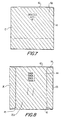
- Figure 7 is a front elevational view of a completed package sleeve made in accordance with the sequential views of Figures 3 through 6;
- Figure 8 is a rear elevational view of the package sleeve of Figure 7;
- Figure 9 is a front elevational view of a label assembly in accordance with the teachings of the present invention;
- Figure 10 is a partial rear elevational view of the label assembly of Figure 9;
- Figure 11 is a front perspective view of the label assembly of Figures 9 and 10 being applied to the finished package sleeve illustrated in Figures 7 and 8;
- Figure 12 is a rear perspective view of the label assembly of Figures 9 and 10 being applied to the finished package sleeve illustrated in Figures 7 and 8; and
- Figure 13 is a front perspective view of a preferred embodiment for applying the label assembly of Figures 9 through 12 to the finished package sleeve illustrated in Figures 7 and 8.
- Referring to Figures 1 and 2, a carton blank 10 for forming a package sleeve for containing storage media discs in accordance with the teachings of the present invention is illustrated. More specifically, Figure 1 illustrates one side of the carton blank and Figure 2 illustrates the opposite side thereof.
- As is shown in Figures 1 and 2, the blank includes a
front panel 12 and aback panel 14 connected to thefront panel 12 alongfold line 15. Thefront panel 12 is comprised of afront portion 16 and a firstouter flap portion 18 connected to thefront portion 16 alongbend line 21. Theback panel 14 of the blank is comprised of aback portion 20 and a secondouter flap portion 22 connected to theback portion 20 alongbend line 24. Twoside flap portions front portion 16 alongbend lines front panel 12,back panel 14,front portion 16,outer flap portions back portion 20 andside flap portions - In the preferred embodiment, the carton blank 10 has the following properties:
Basis Weight, lbs/3,000 Sq. Ft. 172 gam 279.9 Caliper, .001 inch 14.0 mm 0.356 Stiffness, Taber MD 132 CD 65 mNm MD 12.95 CD 6.38 Brightness, % CS 83.0 UCS 82.5 Moisture, % 5.8 Gloss, % CS 57 Smoothness CS 29 (Sheffield Units) UCS 185 - The process for making the package sleeve of the present invention is illustrated in Figures 3 through 6. Initially, the first
outer flap portion 18 is folded alongfold line 21 in the direction of arrow A as shown in Figure 3 such that theglue area 34 provided on theside 18b ofouter flap portion 18 is adhesively attached to theside 16b offront portion 16. Next, as is illustrated in Figure 4, the secondouter flap portion 22 is folded alongfold line 24 in the direction of arrow B such that theglue area 36 provided on theside 22b ofouter flap portion 22 is adhesively attached to theside 20b ofback portion 20. Theback portion 20 with theouter flap portion 22 adhered thereto are then folded alongfold line 15 in the direction of arrow C (see Fig. 5) such that theouter flap portion 22 is aligned with theouter flap portion 18. Subsequent thereto, the twoside flap portions fold lines glue areas respective sides rear portion 20. As a result thereof, asleeve cavity 42 is formed betweenouter flap portions sleeve cavity 42. - As is best shown in Figures 7 and 8, a package sleeve for accommodating storage media disk is therefore provided having a
front panel 12 and aback panel 14 connected thereto alongfold line 15 with the twoside flap panels front panel 12. Thefront panel 12 is in the form of a first folded-over double panel including theouter flap portion 18 and thefront portion 16 and theback panel 14 is in the form of a second folded-over double panel including theouter flap portion 22 and theback portion 20. As is shown in Figures 6 and 8, the twoside flap portions back panel 14 to form thesleeve cavity 42 between the outer flap portion sides 18b and 22b for containment of the storage disc media therein. - As is shown in the figures, the
side flap portions - The
carton blank 10 of Figures 1 and 2 has also been specifically designed to accommodate a storage media disc (i.e., compact or ROM compact disc) having a diameter no greater than 12cm. As designed, the overall blank 10 has a dimension of approximately 19 3/4" in length and 6 5/8" in width. Thefront portion 16 has a dimension of approximately 5" in length and 5 1/8" in width whereas theback portion 20 has a dimension of approximately 5" in length and 4 15/16" in width. Theouter flap portions - These internal dimensions of the sleeve assist in keeping the disc trapped after insertion. The package sleeve of the present invention can be turned open side down and shaken without the disc becoming dislodged. The only way to remove the disc from the sleeve is to apply light pressure to the sides of the sleeve in order to make the sleeve cavity "pucker." Without this external pressure on the sleeve the disc remains gently held in place by the extreme outer edge non-program area of the disc.
- The package sleeve of the present invention also has printed
areas 44 on one side of thefront portion 16,back portion 20 andside flap portion areas 44 appear on the exterior surface of the package sleeve (see Figures 7 and 8) for visual display to the purchaser. - In accordance with one of the general objects of this invention, the side of the package sleeve containing the printed area (i.e., the side of the carton blank 10 shown in Figure 1) is treated with a coating to provide scratch resistance for the storage media disc. This coating is preferably an aqueous-based acrylic clear coating. One such representative aqueous-based acrylic clear coating is manufactured by Algan, Inc. under the trade designation Algloss Overcoating 3048. This coating typically has the following physical properties:
Viscosity : 30-35 seconds, #3 Zahn cup @ 70°F pH : 8.0-9.0 Non-Volatiles : 40-42% VOC : 1.4 lbs/gallon minus water Weight/Gallon : 8.5-8.7 lbs Freeze/Thaw : Stability One cycle sleeve cavity 42 in the finished package sleeve (see Figures 7 and 8) will be so coated. Thus, the interior surfaces and edges of this package sleeve will not scratch of otherwise damage the audio or ROM compact disc when it is contained in thesleeve cavity 42. - The package sleeve of the present invention does not require the additional paper products for the back lines and the booklet of the jewel box as the associated identification and graphics are printed directly to the external point surfaces of the sleeve. This minimizes the chances for mixed orders in comparison to the jewel box design. Additionally, the package sleeve of the present invention is of a reduced weight as compared to the jewel box design. The package sleeve of the present invention is thus a more economical alternative for packaging compact discs (audio or ROM) in comparison to the standard styrene jewel case. It offers both a reduction in material and shipping/storage costs.
- Moreover, this chipboard package sleeve offers complete protection during handling/shipping of both audio and ROM compact discs as interior surfaces and edges of the sleeve that the disc come in contact are treated with a coating such that they will not damage the disc. Further, this package sleeve is readily adaptable to automated assembly processes. The package sleeve of the present invention with its uniform [thickness] cross section thickness resulting from a uniform sleeve cavity or pocket using full-sized panels and external gluing flaps allows the sleeve to stack without leaning profusely as will occur if the sleeve had thickness differences. This stacking uniformity allows more empty sleeves to be stored in a feed magazine with respect to automated inserting of discs into sleeves which is important for efficiency and throughput.
- The package sleeve of the present invention also provides protection to the disc but is more immune to incidental contact than the jewel box allowing the package to accept rough handling without damage or defect.
- As described below, another aspect of the present invention relates to a label assembly for the aforedescribed package sleeve, as illustrated in Figs. 9 through 11.
- Referring now to Figure 9, the
label assembly 50 of the present invention has an overall dimension of approximately 4 7/8" in width and 3 1/2" in length and includes three sections: namely; atear strip 52 and respective first and second faces orparts tear strip 52. In order for the label assembly to be applied to a package sleeve, the first and second faces 54 and 56 have respectiveadhesive backings 70 and 72 (see Fig. 10). - As is shown in Fig. 11, when applied to the
package sleeve 10, thetear strip 52 covers thesleeve cavity 42 so that the storage media disc accommodated within the sleeve cavity will be sealed therein until ready for use. Thetear strip 52 includes a pair ofperforation lines sleeve cavity 42, apull tab 62 provided on thetear strip 52 is lifted and the tear strip is detached along the perforation lines 58 and 60. - In the preferred embodiment, the
tear strip 52 is approximately 1/2" in length and thepull tab 62 extends approximately 3/16" in width from the width of the first and second faces 54 and 56 of the label assembly. - In accordance with one of the general objects of the present invention, the
tear strip 52 of thelabel assembly 50 of the present invention not only seals the open end of thesleeve cavity 42 but is also designed such that it will not scratch or place adhesive on the disc. In accordance therewith, thetear strip 52 includes a deadenedadhesive portion 63 covering and facing the open end of the sleeve cavity to assure that no adhesive can contact the disc (see Fig. 10). - The tear strip width is preferably approximately 0.5" so that this label assembly cannot only be used with a package sleeve accommodating a single storage media disc but also be used with package sleeves accommodating double, triple, quad, etc. storage media discs. This label assembly could then be utilized to close multiple single disc package sleeves that are glued together.
- In order to distribute a single title within the package sleeve to multiple address locations, the
first face 54 of thelabel assembly 50 includes identifyingmailing information 64 printed thereon for shipping (see Fig. 9). This identifyingmailing information 64 can include information such as themailing address 65 of the recipient of the package sleeve, the return address of the sender,postal indicia 67 and a postal bar code. In the preferred embodiment, thefirst face 54 is approximately 2 1/2" in length. - As illustrated in Fig. 9, the
second face 56 includesproduct identification information 66 regarding the particular disc accommodated within the package sleeve or a product identification bar code regarding the disc. In addition, an addressverification bar code 70 can be included on thesecond face 56 which references thespecific mailing information 64 on thefirst face 54 oflabel assembly 50 which is to be used by an address verification system. - More specifically, in one preferred embodiment, this
product identification information 66 can includetext information 68 regarding the disc accommodated within the package sleeve and a product identification bar code (not shown) regarding the disc. As a result thereof, this product identification information assists in tracking the disc in inventory as well as providing additional consumer information regarding the disc. In the preferred embodiment, thesecond face 56 is approximately 1/2" in length. - Advantageously, the label material is vinyl for strength (preferably, Walace #401 Kimdura synthetic vinyl), glossy white for appearance and has a permanent adhesive for security. The label material is also print and apply compatible. Thus, the identifying
mailing information 64 andproduct identification information 66 can be printed onto the label assembly immediately before the label assembly is applied to the package sleeve. - As is shown in Figs. 11 and 12, the present invention also relates to a method for sealing a package sleeve. In this method, the
sleeve cavity 42 of the package sleeve is covered with theremovable tear strip 52 to reliably seal the sleeve cavity and retain the storage media disc within the sleeve cavity. When thestrip 52 covers the sleeve cavity, the deadenedadhesive portion 63 of thetear strip 52 faces the sleeve cavity so that no adhesive can contact the disc accommodated within the sleeve cavity. When it is desired to remove the storage media disc from the sleeve cavity, thepull tab 62 is lifted upwardly such that thetear strip 52 is detached alongperforation lines - As is set forth below, the present invention further relates to a method for providing mailing information and product identification information regarding the package sleeve and disc accommodated therein. Initially, the first and second faces 54 and 56 of the label assembly are folded inwardly along the perforation lines 58 and 60. The
adhesive backing 70 of thefirst face 54 is then adhesively attached to the front portion 16a (see Figs. 7 and 11) of the package sleeve. As a result thereof, themailing identification information 64 of thefirst face 54 is attached to the front portion 16a. Similarly, theadhesive backing 72 of thesecond face 56 is adhesively attached to the rear portion 20a (see Figs. 8 and 12) of the package sleeve. In this manner, theproduct identification information 66 of thesecond face 56 is attached to back portion 20a. When adhesively applied, themailing identification information 64 and theproduct identification information 66 are exposed and therefore the information contained thereon can be visually read and/or scanned with a bar code reader. - The
label assembly 50 of the present invention can be automated using a one step process. Speeds can be approximately 60 parts per minute with each part having a 0.4-0.5 second dwell. Physically, the automation cell can be less than approximately 4 feet in length. - This one-step automated process is shown in Figure 13. The
label assembly 50 is fed out of a printer (not shown) onto a tampblock 80 supported by a pair of guide rods 82a and 82b. The package sleeve is in a staged position between a pair of spring loadedrollers 84a and 84b of the tampblock 80. Upon actuation of a tampcylinder 86, the tampblock 80 is moved in generally the direction of arrow f such that the spring loadedrollers 84a and 84b impart a force respectively to thefirst face 54 andsecond face 56 of the label assembly to move thefaces first face 54 is attached to the front face 16a of the package sleeve and thesecond face 56 is attached to the rear face 20a of the package sleeve by means of theadhesive backings - Based upon the foregoing, the label assembly of the present invention when applied to a package sleeve forms a secure package by which a single CD-ROM can be mailed. Upon receipt, the pull tab is lifted and the deadened tear strip is removed to open the sleeve. The disc accommodated in the sleeve cavity can then be removed without damage. The label assembly is further designed so that all necessary mailing information is printed on the label just before it is automatically applied. As a result, the label assembly of the present invention is a cost effective means to distribute a single title to multiple address locations. In addition, the combination package sleeve/label assembly is economical to mail due to its reduced size and weight.
- While the present invention has been shown and described with reference to certain preferred embodiments, it will be readily apparent to those of ordinary skill in the art that various changes and modifications may be made therein without departing from the spirit and scope of the invention. For instance, an identifying bar code can be printed on the back of each label assembly so that a bar code reader can scan each printed label after application. A data base can then compare "Finished Work" to "Requested Work" with any discrepancies noted. This closed loop address verification can be extended to a serialized CD-ROM with an identifying bar code sticker which can also be scanned with a bar code reader. This additional information can also be written to the "Finished Work" data base. A report can then be generated to show the exact address location of the particular package sleeve.
- It is intended that the appended claims be interpreted as including the foregoing as well as various other changes and modifications.
Claims (21)
- A package sleeve and label assembly comprising a package sleeve including a sleeve cavity (42) for accommodating a storage media disc therein and having a front portion (12) and a back portion (14) opposed to said front portion, and a label assembly (50) adhesively applied to said package sleeve so as to form in cooperation with said package sleeve a mailable sleeve assembly, said label assembly comprising a unitary structure formed of a combination of a removable tear strip (52), a first face (54) including mailing identification information means (64, 65) for identifying mailing information regarding the package sleeve and a second face (56) including product identification information means (66, 68) for providing product identifying information regarding the storage media disc accommodated within the package sleeve wherein said first face (54) and said second face (56) are provided on opposite sides of said tear strip (52), said tear strip providing a closure flap for the sleeve cavity so as to retain the disc in the sleeve cavity and, upon removal thereof from the label assembly the disc can be easily removed from and re-inserted into the sleeve cavity and said first face remains applied to said front portion and said second face remains applied to said back portion.
- A package sleeve and label assembly according to claim 1, wherein said mailing identification information means (64, 65) provided on said label assembly (50) are adhesively applied to said front portion of said package sleeve and said product identification information means (66, 68) provided on said label assembly being adhesively attached to said back portion of said package sleeve, said tear strip (52) having a non-adhesive portion (63) facing the sleeve cavity so that no adhesive can contact the disc.
- The assembly of claim 1 or 2, wherein said tear strip is a perforated tear strip (52, 58, 60).
- The assembly of claim 1, 2, 3 or 4, wherein said label assembly is vinyl.
- The assembly of claim 1, 2, 3 or 4 wherein said mailing identification information means includes mailing identification information selected from the group consisting of a mailing address, a return address, postal indicia and means for encoding postal information.
- The label assembly of claim 1, 2, 3, 4 or 5 wherein said mailing identification information means includes means for encoding postal information which is a postal bar code.
- The package sleeve label assembly of claim 1, 2, 3, 4, 5 or 6, wherein said disc identification information means includes disc identification information selected from the group consisting of text information regarding the disc and means for encoding disc information.
- The label assembly of claim 1, 2, 3, 4, 5, 6 or 7, wherein said disc identification information means includes means for encoding disc information which is a product identification bar code (70) for the disc.
- The assembly of any preceding claim wherein an address verification bar code is provided on said second face of said label assembly.
- An assembly according to any preceding claim, wherein the said package sleeve for accommodating a storage media disc therein comprises a front panel providing the said front portion and a back panel providing the said back portion connected thereto, and two side flap portions (26, 28) connected to said front panel (12), said front panel comprises a first folded-over double panel (12, 18) having two folded layers of relatively the same size and said back panel comprises a second folded-over double panel (14, 22) and said side flap portions are adhesively attached (38, 48) to said back panel to form a sleeve cavity between said first and second folded-over double panels with an opening (42) formed in said sleeve cavity into which the storage media disc is inserted and removed, and wherein said side flap portions (28, 26) are adhesively attached to said back panel along an exterior surface of said back panel which does not form part of said sleeve cavity and does not form a portion of either of said first or second folded-over double panels, and wherein said side flap portions when adhesively attached to said back panel permit said storage media disc to be inserted into and removed from said opening of said sleeve cavity.
- The assembly of claim 10 wherein at least the portions of said first and second folded-over double panels facing said sleeve cavity are treated with a coating to provide scratch resistance for the storage media disc.
- An assembly according to any one of claims 1 to 9 wherein the package sleeve comprises;(a) first and second side flap portions (26, 28) connected to said front portion (16) along respective first and second bend lines (30, 32);(b) the back portion (20) being connected to said front portion (16) along a third bend line (15);(c) top and bottom outer flap portions (18, 22) connected respectively to said front portion (16) and to said back portion (20) along respective fourth and fifth bend lines (21, 24); and(d) wherein said top outer flap portion (18) is folded along said fourth bend line (21) and adhesively attached to said front portion to provide a first folded-over double panel having two folded layers of relatively the same size, said bottom outer flap portion (22) is folded along said fifth bend line (24) and adhesively attached to said back portion to provide a second folded-over double panel having two folded layers of relatively the same size, said back portion and said bottom outer flap portion adhered thereto are folded along said third bend line, and said first and second side flap portions are respectively folded along said first and second bend lines and attached to said back portion by adhesive means to thereby form a sleeve cavity between said top and bottom outer flap portions with an opening formed in said sleeve cavity into which the storage media disc is inserted and removed, and wherein said side flap portions are adhesively attached to said back portion along an exterior surface of said back portion which does not form part of said sleeve cavity and does not form a portion of either of said first or second folded-over double panels, and wherein said side flap portions when adhesively attached to said back panel permit said storage media disc to be inserted into and removed from said opening of said sleeve cavity.
- A method of sealing a package sleeve having a front portion and a back portion and which accommodates information media within a sleeve cavity provided between the front and rear faces, said method comprising the steps of sealing the sleeve cavity with an adhesive label assembly so as to form in cooperation with said package sleeve a mailable sleeve assembly with said label assembly comprising a unitary structure formed of a combination of a removable tear strip, mailing identification information means for identifying mailing information regarding the package sleeve and product identification information means for product identifying information regarding the information media accommodated within the package sleeve, wherein said mailing identification means and said product identification means are provided on opposite sides of said tear strip, said tear strip providing a closure flap for the sleeve cavity so as to retain the information media in the sleeve cavity, and adhesively applying said mailing identification information means provided on said label assembly to said front portion of said package sleeve and adhesively applying said product identification information means provided on said label assembly to said back portion of said package sleeve, said tear strip being detachable from said label assembly along perforation lines provided in said label assembly to enable removal of the information media from the sleeve cavity and reinsertion of the information media into the sleeve cavity.
- A method according to claim 13, wherein the steps of applying the first and second faces of the label assembly respectively to the front and back portions of the package sleeve occur in a single operation.
- The method of claim 13 or 14 and further comprising the step of detaching said tear strip along perforation lines provided in said label assembly to remove the information media from the sleeve cavity.
- The method of claim 13, 14 or 15 and further comprising the step of positioning a non-adhesive portion of said tear strip to face said sleeve cavity so that no adhesive can contact the information media.
- The method of claim 13, 14, 15 or 16 wherein said mailing identification information is mailing identification information selected from the group consisting of a mailing address, a return address, postal indicia and a postal bar code.
- The method of claim 13, 14, 15, 16 or 17 wherein said media identification information is media identification information selected from the group consisting of text information regarding the information media and a product identification bar code regarding the information media.
- A method according to claim 13, 14, 15, 16, 17 or 18 further comprising the step of detaching the tear strip from the assembly and removing the information media.
- A method of making a package sleeve for accommodating information media therein from a carton blank comprising a front portion, first and second side flap portions connected to said front portion along respective first and second bend lines, a back portion connected to said front portion along a third bend line, and top and bottom outer flap portions connected respectively to said front portion and to said back portion along respective fourth and fifth bend lines and for sealing the package sleeve, said method comprising the steps of:(a) folding said top outer flap portion along said fourth bend line;(b) adhesively attaching said top outer flap portion to said front portion;(c) folding said bottom outer flap portion along said fifth bend line;(d) adhesively attaching said bottom outer flap portion to said back portion;(e) folding said back portion and said bottom outer flap portion adhered thereto along said third bend line;(f) folding said first and second side flap portions along respectively said first and second bend lines, respectively;(g) adhesively attaching said first and second side flap portions to said back portion to thereby form a sleeve cavity between said top and bottom outer flap portions with an opening in said sleeve cavity and said side flap portions when attached to said back portion.(h) sealing the sleeve cavity with a label assembly comprising a unitary structure formed of a combination of a removable tear strip, mailing identification information means for identifying mailing information regarding the leakage sleeve and product identification information means for providing product identifying information regarding the information media accommodated within the package sleeve with said tear strip covering the sleeve cavity so as to form in cooperation with said package sleeve a mailable sleeve assembly and to provide a closure flap for the opening of said sleeve cavity so as to retain the information media in the sleeve cavity;(i) adhesively applying a first face of said label assembly including said mailing identification information means to the front panel of the package sleeve; and(j) adhesively applying a second face of said label assembly including said product identification information means including media identification information and an address verification bar code to the back panel of the package sleeve, wherein the steps of applying the first and second faces of said label assembly respectively to the front and back portions of the package sleeve occur in a single operation.
- The method of claim 19 and further comprising the step of positioning a non-adhesive portion of said tear strip to face said sleeve cavity so that no adhesive can contact the information media.
Applications Claiming Priority (5)
| Application Number | Priority Date | Filing Date | Title |
|---|---|---|---|
| US26168194A | 1994-06-17 | 1994-06-17 | |
| US261681 | 1994-06-17 | ||
| US40771795A | 1995-03-21 | 1995-03-21 | |
| US407717 | 1995-03-21 | ||
| PCT/US1995/007638 WO1995035247A1 (en) | 1994-06-17 | 1995-06-16 | Package for media disc and label assembly therefor |
Publications (3)
| Publication Number | Publication Date |
|---|---|
| EP0765284A1 EP0765284A1 (en) | 1997-04-02 |
| EP0765284A4 EP0765284A4 (en) | 1999-11-24 |
| EP0765284B1 true EP0765284B1 (en) | 2006-05-31 |
Family
ID=26948767
Family Applications (1)
| Application Number | Title | Priority Date | Filing Date |
|---|---|---|---|
| EP95924597A Expired - Lifetime EP0765284B1 (en) | 1994-06-17 | 1995-06-16 | Package for media disc and label assembly therefor |
Country Status (10)
| Country | Link |
|---|---|
| US (1) | US5722538A (en) |
| EP (1) | EP0765284B1 (en) |
| JP (1) | JPH10504787A (en) |
| KR (1) | KR100421323B1 (en) |
| CN (2) | CN1235779C (en) |
| AT (1) | ATE328338T1 (en) |
| AU (1) | AU2903095A (en) |
| DE (1) | DE69535021T2 (en) |
| SG (2) | SG94699A1 (en) |
| WO (1) | WO1995035247A1 (en) |
Families Citing this family (38)
| Publication number | Priority date | Publication date | Assignee | Title |
|---|---|---|---|---|
| US5857707A (en) * | 1996-05-02 | 1999-01-12 | Devlin; Stephen M. | Jukebox display strip and method of making same |
| WO1998048423A2 (en) * | 1997-04-22 | 1998-10-29 | Prefix Gmbh Agentur Für Multimedia Und Musik | Delivery packaging with a disc-shaped information carrier, and a method and device for producing the same |
| GB2331981B (en) * | 1997-12-05 | 2001-06-20 | Dubois Ltd | Enclosure holding data carrier |
| GB2335410B (en) * | 1998-02-26 | 2002-05-22 | Selwyn Pires | Improvements in pouches |
| ATE298126T1 (en) * | 1999-10-20 | 2005-07-15 | Fountain Tech Bv | ARRANGEMENT FOR SENDING COMPACT DISCS (CD'S) OR SIMILAR DISK-FORM DATA MEDIA |
| US6360466B1 (en) * | 2000-05-19 | 2002-03-26 | Iomega Corporation | Data storage cartridge with multiple labels |
| US6499654B1 (en) * | 2000-07-27 | 2002-12-31 | The Scene Production | Postcard for carrying compact disk |
| US6902054B2 (en) * | 2001-08-27 | 2005-06-07 | Mckean Patrick Steven | Media jewel case |
| JP4055045B2 (en) * | 2001-10-25 | 2008-03-05 | 株式会社日立グローバルストレージテクノロジーズ | Rotating disk type storage device |
| US6684980B2 (en) | 2002-01-02 | 2004-02-03 | Khsh Enterprises, Llc | Minimal inventory package and delivery system in a retail business environment |
| US20030160097A1 (en) * | 2002-02-28 | 2003-08-28 | Gerald Steiner | Package and method for merchandise return via mail |
| US6966484B2 (en) * | 2002-09-16 | 2005-11-22 | Netflix, Inc. | Mailing and response envelope |
| US7549571B2 (en) * | 2002-09-18 | 2009-06-23 | Ecoenvelopes, Llc | Environmentally friendly reusable envelope structures |
| JP2004189307A (en) * | 2002-12-13 | 2004-07-08 | Showa Packs Kk | Pleated bag |
| US20040112789A1 (en) * | 2002-12-17 | 2004-06-17 | Robinson Ian Douglas | Protective envelope package for flash memory devices |
| US6991101B2 (en) * | 2003-04-21 | 2006-01-31 | Bennett David W | Device for labeling and storing computer discs |
| US20060180486A1 (en) * | 2003-04-21 | 2006-08-17 | Bennett David W | Modular panel and storage system for flat items such as media discs and holders therefor |
| US6951279B2 (en) * | 2003-10-07 | 2005-10-04 | Gamefly, Inc. | System and apparatus for protecting digital media |
| US20050106340A1 (en) * | 2003-11-13 | 2005-05-19 | Bjk Holdings, Inc. | Packaging label having a tear away spine |
| WO2005082056A2 (en) * | 2004-02-25 | 2005-09-09 | Ecoenvelopes, Llc | Reusable envelope structures and methods |
| US8763891B1 (en) | 2004-02-25 | 2014-07-01 | Carol A. DeLaVergne | Reusable envelope structures and methods |
| KR20040082367A (en) * | 2004-09-07 | 2004-09-24 | 박상철 | The cutting sticker added wrap vinyl |
| AU2006231502A1 (en) * | 2005-04-05 | 2006-10-12 | Ecoenvelopes, Llc | Reusable envelope structures and methods |
| US20080121543A1 (en) * | 2006-08-08 | 2008-05-29 | Kamile Bartlett | Coordination System & Method |
| CA2661037A1 (en) * | 2006-08-18 | 2008-02-28 | Ecoenvelopes, Llc | Reusable envelopes |
| DE202008007081U1 (en) * | 2007-12-04 | 2008-08-07 | Bachmayr, Amadeus | Packaging and cutting for a packaging |
| US20100038414A1 (en) * | 2008-07-10 | 2010-02-18 | Delavergne Carol A | Reusable mailers and methods |
| US8875985B1 (en) | 2009-02-19 | 2014-11-04 | eco Envelopes, LLC. | Conversion envelopes |
| US9617041B1 (en) * | 2009-02-19 | 2017-04-11 | Ecoenvelopes, Llc. | Conversion envelopes |
| US9466335B2 (en) | 2011-04-28 | 2016-10-11 | Entrotech, Inc. | Hermetic hard disk drives comprising integrally molded filters and related methods |
| USD668718S1 (en) * | 2011-05-27 | 2012-10-09 | Life Technologies Corporation | Label |
| WO2015164551A1 (en) | 2014-04-22 | 2015-10-29 | Entrotech, Inc. | Re-workable sealed hard disk drives, cover seals therefor, and related methods |
| EP3152757A1 (en) | 2014-06-09 | 2017-04-12 | Entrotech, Inc. | Laminate-wrapped hard disk drives and related methods |
| US20160240111A1 (en) * | 2015-02-18 | 2016-08-18 | Karen Rachel Beber Futernick | Perforated label assembly |
| US9601161B2 (en) | 2015-04-15 | 2017-03-21 | entroteech, inc. | Metallically sealed, wrapped hard disk drives and related methods |
| US9878825B1 (en) | 2015-06-02 | 2018-01-30 | Ecoenvelopes, Llc | Reusable top flap envelope with dual opposing seal flaps |
| US11479029B2 (en) * | 2020-02-21 | 2022-10-25 | Mar-Co Packaging, Inc. | Paper label with polymer film reinforcement and method of manufacture |
| US20230260429A1 (en) * | 2022-02-16 | 2023-08-17 | Iconex Llc | Zippered Label-Liner Combination |
Family Cites Families (18)
| Publication number | Priority date | Publication date | Assignee | Title |
|---|---|---|---|---|
| US1464378A (en) * | 1921-12-28 | 1923-08-07 | Wilburger William | Envelope for disk records |
| US1827636A (en) * | 1929-03-07 | 1931-10-13 | Charles H Ames | Means for sealing packages |
| US3337119A (en) * | 1963-09-20 | 1967-08-22 | Clyde T Bowers | Envelope |
| US3426960A (en) * | 1967-09-28 | 1969-02-11 | Paul B Shore | Phonograph record receiving jacket |
| US3717297A (en) * | 1971-03-11 | 1973-02-20 | Creative Posters Inc | Disc record carrier |
| US3767038A (en) * | 1972-09-07 | 1973-10-23 | H Channing | Composite label and battery package |
| US4771891A (en) * | 1986-06-12 | 1988-09-20 | Avery International Corporation | Patterned adhesive label structures |
| US4905831A (en) * | 1988-11-23 | 1990-03-06 | Chronos Incorporated | Magnetic diskette package |
| US5048681A (en) * | 1989-04-27 | 1991-09-17 | Henkel Walter R | Envelope storage for compact discs |
| US5071167A (en) * | 1990-07-27 | 1991-12-10 | Avery International | Shipping and return mailing label |
| US5118375A (en) * | 1990-08-09 | 1992-06-02 | Xerox Corporation | Method and apparatus for making envelopes on-line for direct mail application |
| US5217307A (en) * | 1990-12-07 | 1993-06-08 | Morgan Adhesives Company | Container with an easy opening indicator or security break indicator |
| US5188229A (en) * | 1991-04-05 | 1993-02-23 | International Paper Company | Compact disc package |
| US5154284A (en) * | 1991-11-07 | 1992-10-13 | Starkey Merrily J | Compact disc packaging |
| US5248032A (en) * | 1992-09-09 | 1993-09-28 | Ivy Hill Corporation | Compact disc jacket |
| US5318222A (en) * | 1993-02-01 | 1994-06-07 | Ames Safety Envelope Co. | Mailer for computer disks |
| US5333728A (en) * | 1993-08-30 | 1994-08-02 | Ivy Hill Corporation | Compact disc jacket and blank therefor |
| DE9415794U1 (en) * | 1994-09-26 | 1995-01-19 | Moebius Gert C | Multi-part folding sleeve for electronic media carriers |
-
1995
- 1995-06-16 AU AU29030/95A patent/AU2903095A/en not_active Abandoned
- 1995-06-16 EP EP95924597A patent/EP0765284B1/en not_active Expired - Lifetime
- 1995-06-16 WO PCT/US1995/007638 patent/WO1995035247A1/en active IP Right Grant
- 1995-06-16 SG SG9704448A patent/SG94699A1/en unknown
- 1995-06-16 AT AT95924597T patent/ATE328338T1/en not_active IP Right Cessation
- 1995-06-16 CN CN00118181.5A patent/CN1235779C/en not_active Expired - Fee Related
- 1995-06-16 DE DE69535021T patent/DE69535021T2/en not_active Expired - Fee Related
- 1995-06-16 JP JP8502491A patent/JPH10504787A/en active Pending
- 1995-06-16 KR KR1019960700811A patent/KR100421323B1/en not_active IP Right Cessation
- 1995-06-16 CN CN95190732A patent/CN1079358C/en not_active Expired - Fee Related
- 1995-06-16 SG SG9704446A patent/SG94698A1/en unknown
-
1996
- 1996-10-08 US US08/729,773 patent/US5722538A/en not_active Expired - Lifetime
Also Published As
| Publication number | Publication date |
|---|---|
| DE69535021D1 (en) | 2006-07-06 |
| KR100421323B1 (en) | 2004-05-20 |
| CN1289709A (en) | 2001-04-04 |
| CN1235779C (en) | 2006-01-11 |
| DE69535021T2 (en) | 2006-11-30 |
| JPH10504787A (en) | 1998-05-12 |
| AU2903095A (en) | 1996-01-15 |
| ATE328338T1 (en) | 2006-06-15 |
| WO1995035247A1 (en) | 1995-12-28 |
| EP0765284A4 (en) | 1999-11-24 |
| US5722538A (en) | 1998-03-03 |
| SG94699A1 (en) | 2003-03-18 |
| CN1135201A (en) | 1996-11-06 |
| EP0765284A1 (en) | 1997-04-02 |
| CN1079358C (en) | 2002-02-20 |
| SG94698A1 (en) | 2003-03-18 |
Similar Documents
| Publication | Publication Date | Title |
|---|---|---|
| EP0765284B1 (en) | Package for media disc and label assembly therefor | |
| US5697496A (en) | Package for compact disks or computer diskettes | |
| US4570416A (en) | Overnight package | |
| US9511919B2 (en) | Methods and apparatus for prepaid card packaging | |
| US5460265A (en) | Blank construction and package for a compact disc | |
| US4134495A (en) | Single size display carton for packaging either a tape cassette or tape cartridge | |
| US5857565A (en) | Paperboard envelope for a computer disc or CD which is insertable in a bound publication | |
| US4314635A (en) | Checking account check and check book order-taking portfolio | |
| US5772019A (en) | Packaging arrangement for storage discs and method for making the same | |
| US5909805A (en) | Label assembly for package sleeve accommodating a storage media disc and method for sealing a package sleeve | |
| US6446417B1 (en) | Article-embedded folding sleeve and method for producing same | |
| US6685226B2 (en) | Carrier for information storage unit and method | |
| US6688648B2 (en) | Carrier for information storage unit and method | |
| US6923366B2 (en) | Box with pocket for extractable leaflet | |
| US20040011858A1 (en) | Box with pocket for illustrative leaflet | |
| US20040011685A1 (en) | Media packaging sleeve | |
| US20050252801A1 (en) | Mailer assembly for transporting fragile media | |
| GB2467926A (en) | Package for mailing items such as DVDs and CDs | |
| JP3048786U (en) | Paper CD package | |
| US20060000727A1 (en) | Compact disc mailer | |
| CA2073792A1 (en) | Consumer package with fully visible product information display | |
| JPH11165740A (en) | Package for mailing information storage medium | |
| JPS62220440A (en) | Packaging box | |
| JPH10236566A (en) | Package for direct mail | |
| CN1203177A (en) | Semi-closed packing bag for books and periodicals and magazines and packing method thereof |
Legal Events
| Date | Code | Title | Description |
|---|---|---|---|
| PUAI | Public reference made under article 153(3) epc to a published international application that has entered the european phase |
Free format text: ORIGINAL CODE: 0009012 |
|
| 17P | Request for examination filed |
Effective date: 19960215 |
|
| AK | Designated contracting states |
Kind code of ref document: A1 Designated state(s): AT DE FR GB |
|
| RHK1 | Main classification (correction) |
Ipc: G09F 3/00 |
|
| A4 | Supplementary search report drawn up and despatched |
Effective date: 19991008 |
|
| AK | Designated contracting states |
Kind code of ref document: A4 Designated state(s): AT DE FR GB |
|
| 17Q | First examination report despatched |
Effective date: 20040819 |
|
| GRAP | Despatch of communication of intention to grant a patent |
Free format text: ORIGINAL CODE: EPIDOSNIGR1 |
|
| GRAS | Grant fee paid |
Free format text: ORIGINAL CODE: EPIDOSNIGR3 |
|
| GRAA | (expected) grant |
Free format text: ORIGINAL CODE: 0009210 |
|
| AK | Designated contracting states |
Kind code of ref document: B1 Designated state(s): AT DE FR GB |
|
| REG | Reference to a national code |
Ref country code: GB Ref legal event code: FG4D |
|
| REF | Corresponds to: |
Ref document number: 69535021 Country of ref document: DE Date of ref document: 20060706 Kind code of ref document: P |
|
| ET | Fr: translation filed | ||
| PLBE | No opposition filed within time limit |
Free format text: ORIGINAL CODE: 0009261 |
|
| STAA | Information on the status of an ep patent application or granted ep patent |
Free format text: STATUS: NO OPPOSITION FILED WITHIN TIME LIMIT |
|
| 26N | No opposition filed |
Effective date: 20070301 |
|
| PGFP | Annual fee paid to national office [announced via postgrant information from national office to epo] |
Ref country code: AT Payment date: 20090615 Year of fee payment: 15 |
|
| PGFP | Annual fee paid to national office [announced via postgrant information from national office to epo] |
Ref country code: GB Payment date: 20090610 Year of fee payment: 15 Ref country code: DE Payment date: 20090615 Year of fee payment: 15 |
|
| GBPC | Gb: european patent ceased through non-payment of renewal fee |
Effective date: 20100616 |
|
| REG | Reference to a national code |
Ref country code: FR Ref legal event code: ST Effective date: 20110228 |
|
| PG25 | Lapsed in a contracting state [announced via postgrant information from national office to epo] |
Ref country code: DE Free format text: LAPSE BECAUSE OF NON-PAYMENT OF DUE FEES Effective date: 20110101 |
|
| PG25 | Lapsed in a contracting state [announced via postgrant information from national office to epo] |
Ref country code: AT Free format text: LAPSE BECAUSE OF NON-PAYMENT OF DUE FEES Effective date: 20100616 Ref country code: FR Free format text: LAPSE BECAUSE OF NON-PAYMENT OF DUE FEES Effective date: 20100630 |
|
| PG25 | Lapsed in a contracting state [announced via postgrant information from national office to epo] |
Ref country code: GB Free format text: LAPSE BECAUSE OF NON-PAYMENT OF DUE FEES Effective date: 20100616 |
|
| PGFP | Annual fee paid to national office [announced via postgrant information from national office to epo] |
Ref country code: FR Payment date: 20090611 Year of fee payment: 15 |