EP0764764B1 - Partially-metallic fan-blade for a gas turbine - Google Patents
Partially-metallic fan-blade for a gas turbine Download PDFInfo
- Publication number
- EP0764764B1 EP0764764B1 EP96306989A EP96306989A EP0764764B1 EP 0764764 B1 EP0764764 B1 EP 0764764B1 EP 96306989 A EP96306989 A EP 96306989A EP 96306989 A EP96306989 A EP 96306989A EP 0764764 B1 EP0764764 B1 EP 0764764B1
- Authority
- EP
- European Patent Office
- Prior art keywords
- proximate
- blade
- solid
- gas turbine
- spars
- Prior art date
- Legal status (The legal status is an assumption and is not a legal conclusion. Google has not performed a legal analysis and makes no representation as to the accuracy of the status listed.)
- Expired - Lifetime
Links
Images


Classifications
-
- F—MECHANICAL ENGINEERING; LIGHTING; HEATING; WEAPONS; BLASTING
- F01—MACHINES OR ENGINES IN GENERAL; ENGINE PLANTS IN GENERAL; STEAM ENGINES
- F01D—NON-POSITIVE DISPLACEMENT MACHINES OR ENGINES, e.g. STEAM TURBINES
- F01D5/00—Blades; Blade-carrying members; Heating, heat-insulating, cooling or antivibration means on the blades or the members
- F01D5/12—Blades
- F01D5/28—Selecting particular materials; Particular measures relating thereto; Measures against erosion or corrosion
- F01D5/282—Selecting composite materials, e.g. blades with reinforcing filaments
-
- F—MECHANICAL ENGINEERING; LIGHTING; HEATING; WEAPONS; BLASTING
- F01—MACHINES OR ENGINES IN GENERAL; ENGINE PLANTS IN GENERAL; STEAM ENGINES
- F01D—NON-POSITIVE DISPLACEMENT MACHINES OR ENGINES, e.g. STEAM TURBINES
- F01D5/00—Blades; Blade-carrying members; Heating, heat-insulating, cooling or antivibration means on the blades or the members
- F01D5/12—Blades
- F01D5/14—Form or construction
- F01D5/147—Construction, i.e. structural features, e.g. of weight-saving hollow blades
-
- Y—GENERAL TAGGING OF NEW TECHNOLOGICAL DEVELOPMENTS; GENERAL TAGGING OF CROSS-SECTIONAL TECHNOLOGIES SPANNING OVER SEVERAL SECTIONS OF THE IPC; TECHNICAL SUBJECTS COVERED BY FORMER USPC CROSS-REFERENCE ART COLLECTIONS [XRACs] AND DIGESTS
- Y02—TECHNOLOGIES OR APPLICATIONS FOR MITIGATION OR ADAPTATION AGAINST CLIMATE CHANGE
- Y02T—CLIMATE CHANGE MITIGATION TECHNOLOGIES RELATED TO TRANSPORTATION
- Y02T50/00—Aeronautics or air transport
- Y02T50/60—Efficient propulsion technologies, e.g. for aircraft
Definitions
- the present invention relates generally to gas turbines, and more particularly to a partially-metallic fan blade for a gas turbine aircraft engine.
- Gas turbines include, but are not limited to, gas turbine power generation equipment and gas turbine aircraft engines.
- a gas turbine includes a core engine having a high pressure compressor to compress the air flow entering the core engine, a combustor in which a mixture of fuel and the compressed air is burned to generate a propulsive gas flow, and a high pressure turbine which is rotated by the propulsive gas flow and which is connected by a larger diameter shaft to drive the high pressure compressor.
- a typical front fan gas turbine aircraft engine adds a low pressure turbine (located aft of the high pressure turbine) which is connected by a smaller diameter coaxial shaft to drive the front fan (located forward of the high pressure compressor) and to drive an optional low pressure compressor (located between the front fan and the high pressure compressor).
- the low pressure compressor sometimes is called a booster compressor or simply a booster.
- the fan and the high and low pressure compressors and turbines have gas turbine blades each including an airfoil portion attached to a shank portion.
- Rotor blades are those gas turbine blades which are attached to a rotating gas turbine rotor disc.
- Stator vanes are those gas turbine blades which are attached to a non-rotating gas turbine stator casing.
- a first and/or last row of stator vanes may have their radially inward ends also attached to a non-rotating gas turbine stator casing.
- Counterrotating "stator" vanes are also known.
- a “composite” is defined to be a material having any (metal or non-metal) fiber filament embedded in any (metal or non-metal) matrix binder, but the term “composite” does not include a metal fiber embedded in a metal matrix.
- metal includes an alloy.
- An example of a composite is a material having graphite filaments embedded in an epoxy resin.
- stator blade comprises a metallic structure having a smooth surface on one side defining one face of the blade and a plurality of cells on its opposite side which are filled with a composite material such as polyurethane, the filled cellular side of the metallic structure defining the other face of the blade.
- the fan blades typically are the largest (and therefore the heaviest) blades in a gas turbine aircraft engine, and the front fan blades are the first to be impacted by a bird strike. What is needed is a gas turbine blade, and especially a gas turbine fan blade, which is both lighter in weight and better resistant to damage from bird strikes.
- a gas turbine aircraft engine fan blade comprising: a shank portion; a solid section; a multiplicity of spaced-apart segments; and a plurality of solid spars, wherein said solid section, said segments, and said solid spars are attached together to define a rotable airfoil portion, and wherein said rotatable airfoil portion includes:
- the solid section of the blade's airfoil portion consisting essentially of metal, provides resistance to damage from bird strikes in those areas of the blade, such as an aircraft fan blade, most prone to bird strike impact damage.
- the segments of the blade's airfbil portion consisting essentially of a composite, a structural foam, and/or a syntactic foam, provides low weight in those areas of the blade, such as an aircraft fan blade, least prone to bird strike impact damage. Such segments are also easily repairable.
- the solid spars of the blade's airfoil portion consisting essentially of metal, supply additional flexural and torsional stiffness to the blade and also act as crack/delamination stoppers by dissipating energy during blade impacts from bird strikes.
- FIG. 1 and 2 schematically show a first preferred embodiment of the gas turbine fan blade 110 of the present invention.
- the gas turbine fan blade 110 includes a shank portion 112, a solid section 114, a multiplicity of spaced-apart segments 116, and a plurality of solid spars 118.
- the shank portion 112 has a blade platform 120, which helps to radially contain the air flow, and a dovetail 122, which attaches to a rotor disc (not shown).
- the solid section 114, the segments 116, and the solid spars 118 are attached together to define an airfoil portion 124.
- the airfoil portion 124 has a leading edge 126, a trailing edge 128, a pressure (concave-shaped) side 130, a suction (convex-shaped) side 132, a blade root 134, a blade tip 136, and a radial axis 138.
- the sides 130 and 132 are joined together at the edges 126 and 128 to define an airfoil shape having a chord line 140 extending from the leading edge 126 to the trailing edge 128 and having a thickness-wise direction 142 perpendicular to the chord line 140 and extending from the pressure side 130 to the suction side 132.
- the blade root 134 is attached to the shank portion 112.
- the radial axis 138 extends outward toward the blade tip 136 and inward toward the blade root 134.
- the solid section 114 consists essentially of a metal material, and preferably consists of a metal material.
- the term "metal" includes an alloy.
- the solid section 114 is a monolithic metal section.
- the metal material consists essentially of (and preferably consists of) titanium.
- Other choices for the metal material include, but are not limited to, aluminum, cobalt, nickel, or steel.
- the solid section 114 includes partially the pressure and suction sides 130 and 132 proximate and including the blade tip 136 from the leading edge 126 to the trailing edge 128 and proximate and including the leading and trailing edges 126 and 128 from the blade root 134 to the blade tip 136. It is noted that such described solid section 114 describes a metal blade tip 136 which provides for better tip-rub protection.
- the segments 116 consist essentially of (and preferably consist of) a material selected from the group consisting of composites, structural foams, syntactic foams, and mixtures thereof.
- the term "composite” is defined to be a material having any (metal or non-metal) fiber filament embedded in any (metal or non-metal) matrix binder, but the term “composite” does not include a metal fiber (i.e., fiber filament) embedded in a metal matrix.
- the segments 116 are composite segments, such composite segments are a layup of discrete composite laminations.
- the composite material consists essentially of (and preferably consists of) carbon fiber filaments embedded in an epoxy (i.e., epoxy resin) matrix binder.
- composite material examples include, but are not limited to, fiber-bismaleimide, fiber-polyimide, and other fiber-epoxy thermoset or thermoplastic resins and mixtures thereof. Fiber-filament modulus and orientation are chosen to maintain overall airfoil-portion stiffness to minimize structural binding of the blade under centrifugal and aerodynamic load, as is within the level of skill of the artisan.
- structural foam is defined to be a plastic having a cellular core and integral skins.
- sintactic foam is defined to be a cellular polymer made by dispersing rigid, microscopic particles in a fluid polymer and then curing it. An example of a syntactic foam is Rohacell Foam. The segments 116 together are bounded in part by the solid section 114 proximate the blade tip 136, the leading edge 126, and the trailing edge 128.
- the solid spars 118 separate and are attached to the segments 116.
- the solid spars consist essentially of (and preferably consist of) a metal material.
- the metal material is the same as that of the solid section 114.
- the solid spars 118 include a first spar 144 extending generally radially from the blade root 134 to proximate the blade tip 136 and extending generally thickness-wise from the pressure side 130 to the suction side 132.
- the solid spars 118 include a second spar 146 extending generally chordwise from proximate the leading edge 126 to proximate the trailing edge 128 and extending generally thickness-wise from the pressure side 130 to the suction side 132.
- the first spar 144 has an end 148 attached to the solid section 114 proximate the blade tip 136
- the second spar 146 has two ends 150 and 152 each attached to the solid section 114 proximate a corresponding one of the leading and trailing edges 126 and 128.
- the segments 116 extend generally thickness-wise from the pressure side 130 to the suction side 132.
- the solid spars 118 together define a monolithic spar array
- the solid spars 118 and the solid section 114 together define a monolithic metallic array.
- a second preferred embodiment of the gas turbine blade 210 is generally identical to the previously-described first preferred embodiment of the gas turbine blade 110 with the following addition.
- the first and second spars 244 and 246 intersect, and the solid spars include a third spar 254 extending from the intersection 256 at an angle of generally forty-five degrees from the radial axis 238 and extending generally thickness-wise (like the first and second spars 244 and 246) from the pressure side to the suction side.
- a third and fourth preferred embodiment of the gas turbine blade 310 and 410 each is generally identical to the previously-described first or second preferred embodiments of the gas turbine blade 110 or 210 with the following differences.
- the airfoil portion 324 of the gas turbine blade 310 has its solid section 314 further include entirely the suction side 332 such that the segments 316 are abutted by the solid section 314 towards the suction side 332.
- all the solid spars 318 extend generally thickness-wise from the pressure side 330 to proximate the suction side 332.
- the solid spars of the gas turbine blade 410 include a core spar 458 extending generally chordwise from proximate the leading edge 426 to proximate the trailing edge 428, extending generally radially from the blade root to the blade tip, and thickness-wise spaced apart from the pressure and suction sides 430 and 432.
- the gas turbine blade 110 rotates in a direction such that the pressure (concave) side 130 passes a reference point before the suction (convex) side 132 passes the same reference point.
- the bird impact footprint is primarily over the metallic solid section 114 area of the pressure side 130 near the leading edge 126, followed by the adjoining composite, structural foam, and/or syntactic foam segments 116 area of the pressure side 130.
- Such composite, structural foam, and/or syntactic foam area provides buckling resistance since it will be in tension, which is best for composites, structural foams, and/or syntactic foams.
- the following percentages of composite, structural foam, and/or syntactic foam segment 116 material making up the airfoil portion 124 have been determined by engineering analysis through optimizing weight and impact resistance factors.
- the segments 116 include between generally forty and ninety percent (and desirably between fifty and eighty percent) of the surface area of the pressure side 130 and includes between generally forty and ninety percent (and desirably between fifty and eighty percent) of the volume size of the airfoil portion 124.
- the segments 116 include generally seventy percent of the surface area of the pressure side 130 and include generally seventy percent of the volume size of the airfoil portion 124.
- the gas turbine blade 110 includes at least four segments 116.
- the segments 116 together extend in a general chordwise direction along the pressure side 130 between generally fifteen and ninety-five percent (and desirably between fifty and eighty percent) of the distance along the pressure side 130 between the leading edge 126 and the trailing edge 128. In a preferred embodiment, the segments 116 together extend generally sixty percent of the distance along the pressure side 130 between the leading edge 126 and the trailing edge 128. It is desired that the segments 116 together extend radially between generally sixty and ninety-five percent (and preferably between generally seventy and ninety-five percent) of the distance between the blade root 134 and the blade tip 136. In an exemplary embodiment, the segments 116 together extend radially generally ninety percent of the distance between the blade root 134 and the blade tip 136.
- the composite (or structural/syntactic foam) material is thermally removable from the solid section 114 at a temperature below the melting point of the metal material. This allows the airfoil portion 124 to be easily repairable should it become damaged due to bird strikes or foreign object impacts. If the airfoil portion is damaged in the composite (or structural/syntactic foam) segments 116, the composite (or structural/syntactic foam) material would be thermally removed, the metal solid section 114 and/or metal solid spars 118 repaired, and new composite (or structural/syntactic foam) material reapplied.
- the airfoil portion 124 is an airfoil portion of a gas turbine aircraft engine fan blade 110 (or the airfoil portion of a gas turbine aircraft engine compressor blade if the engine has no fan).
- the gas turbine blade 110 of the present invention in the form of a gas turbine aircraft engine fan blade, has a preferred diameter of between generally 45 and 98 inches and a preferred design maximum speed at the blade tip 136 of less than generally 1550 feet per second.
- Such preferred operating conditions ensure that the blade tip temperature will not exceed the operating temperature of composite materials, such as epoxy, bismaleimide, and polyimide resins (or structural foam or syntactic foam materials) used in the segments 116 of the airfoil portion 124.
- Preferred methods for making the gas turbine blade 110 of the invention include, but are not limited to, autoclave, compression mold, and (in the case of composite materials) resin transfer molding. If autoclave is chosen, the metal solid section 114 would act as one side of the tool, thus minimizing tooling. As previously mentioned, in the case of composite materials, fiber-filament modulus and orientation would be chosen to maintain overall airfoil-portion stiffness to minimize structural binding of the blade under centrifugal and aerodynamic load, as is within the level of skill of the artisan.
- the dovetail 122 of the shank portion 112 can be partially composite on the pressure (concave) side (not shown).
- the dovetail 122 can have a metal wedge system (also not shown) to positively capture the composite (or structural/syntactic foam) segments 116 and provide a metallic dovetail wear surface.
- less containment structure for the airfoil portion 124 is required since the composite (or structural/syntactic foam) material will fragment and disband from the metallic solid section 114 under impact.
Description
- The present invention relates generally to gas turbines, and more particularly to a partially-metallic fan blade for a gas turbine aircraft engine.
- Gas turbines include, but are not limited to, gas turbine power generation equipment and gas turbine aircraft engines. A gas turbine includes a core engine having a high pressure compressor to compress the air flow entering the core engine, a combustor in which a mixture of fuel and the compressed air is burned to generate a propulsive gas flow, and a high pressure turbine which is rotated by the propulsive gas flow and which is connected by a larger diameter shaft to drive the high pressure compressor. A typical front fan gas turbine aircraft engine adds a low pressure turbine (located aft of the high pressure turbine) which is connected by a smaller diameter coaxial shaft to drive the front fan (located forward of the high pressure compressor) and to drive an optional low pressure compressor (located between the front fan and the high pressure compressor). The low pressure compressor sometimes is called a booster compressor or simply a booster.
- The fan and the high and low pressure compressors and turbines have gas turbine blades each including an airfoil portion attached to a shank portion. Rotor blades are those gas turbine blades which are attached to a rotating gas turbine rotor disc. Stator vanes are those gas turbine blades which are attached to a non-rotating gas turbine stator casing. Typically, there are alternating circumferential rows of radially-outwardly extending rotor blades and radially-inwardly extending stator vanes. When present, a first and/or last row of stator vanes (also called inlet and outlet guide vanes) may have their radially inward ends also attached to a non-rotating gas turbine stator casing. Counterrotating "stator" vanes are also known. Conventional gas turbine blade designs typically have airfoil portions that are made entirely of metal, such as titanium, or are made entirely of a composite. A "composite" is defined to be a material having any (metal or non-metal) fiber filament embedded in any (metal or non-metal) matrix binder, but the term "composite" does not include a metal fiber embedded in a metal matrix. The term "metal includes an alloy. An example of a composite is a material having graphite filaments embedded in an epoxy resin. The all-metal blades, including costly wide-chord hollow blades, are heavier in weight which results in lower fuel performance and which requires sturdier blade attachments, while the lighter all-composite blades suffer more response/damage from bird strikes. Known hybrid blades include a composite blade whose leading edge is protected by metal for erosion and bird impact reasons.
- One known form of stator blade is described in GB-A-2264755, and comprises a metallic structure having a smooth surface on one side defining one face of the blade and a plurality of cells on its opposite side which are filled with a composite material such as polyurethane, the filled cellular side of the metallic structure defining the other face of the blade.
- The fan blades typically are the largest (and therefore the heaviest) blades in a gas turbine aircraft engine, and the front fan blades are the first to be impacted by a bird strike. What is needed is a gas turbine blade, and especially a gas turbine fan blade, which is both lighter in weight and better resistant to damage from bird strikes.
- It is an object of the invention to provide a partially-metallic gas turbine fan blade.
- According to the present invention, there is provided a gas turbine aircraft engine fan blade comprising: a shank portion; a solid section; a multiplicity of spaced-apart segments; and a plurality of solid spars, wherein said solid section,
said segments, and said solid spars are attached together to define a rotable airfoil portion, and wherein said rotatable airfoil portion includes: - a) a leading edge;
- b) a trailing edge;
- c) a pressure side;
- d) a suction side, said sides joined together at said edges to define an airfoil shape having a chord line extending from said leading edge to said trailing edge and having a thickness-wise direction perpendicular to said chord line and extending from said pressure side to said suction side;
- e) a blade root attached to said shank portion;
- f) a blade tip; and
- g) a radial axis extending outward toward said blade tip and inward toward said blade root, wherein said solid section consists essentially of a metal material,
-
- Several benefits and advantages are derived from the gas turbine fan blade of the invention. The solid section of the blade's airfoil portion, consisting essentially of metal, provides resistance to damage from bird strikes in those areas of the blade, such as an aircraft fan blade, most prone to bird strike impact damage. The segments of the blade's airfbil portion, consisting essentially of a composite, a structural foam, and/or a syntactic foam, provides low weight in those areas of the blade, such as an aircraft fan blade, least prone to bird strike impact damage. Such segments are also easily repairable. The solid spars of the blade's airfoil portion, consisting essentially of metal, supply additional flexural and torsional stiffness to the blade and also act as crack/delamination stoppers by dissipating energy during blade impacts from bird strikes.
- The accompanying drawings illustrate several preferred embodiments of the present invention wherein:
- Figure 1 is a schematic side-elevational view of the pressure side of a first preferred embodiment of the gas turbine blade of the present invention in the form of a gas turbine aircraft engine fan blade;
- Figure 2 is a schematic view of the airfoil portion of the gas turbine fan bade of Figure 1, taken along lines 2-2 of Figure 1;
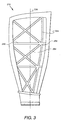
- Figure 3 is a schematic side-elevational view of the pressure side of a second preferred embodiment of the gas turbine fan blade of the invention;
- Figure 4 is a view, as in Figure 2, but of a third preferred embodiment of the gas turbine fan blade of the invention; and
- Figure 5 is a view, as in Figure 2, but of a fourth preferred embodiment of the gas turbine fan blade of the invention.
-
- Referring now to the drawings, wherein like numerals represent like elements throughout, Figures 1 and 2 schematically show a first preferred embodiment of the gas
turbine fan blade 110 of the present invention. The gasturbine fan blade 110 includes ashank portion 112, asolid section 114, a multiplicity of spaced-apart segments 116, and a plurality ofsolid spars 118. Typically, theshank portion 112 has ablade platform 120, which helps to radially contain the air flow, and adovetail 122, which attaches to a rotor disc (not shown). Thesolid section 114, thesegments 116, and thesolid spars 118 are attached together to define anairfoil portion 124. - The
airfoil portion 124 has a leadingedge 126, atrailing edge 128, a pressure (concave-shaped)side 130, a suction (convex-shaped)side 132, ablade root 134, ablade tip 136, and aradial axis 138. Thesides edges chord line 140 extending from the leadingedge 126 to thetrailing edge 128 and having athickness-wise direction 142 perpendicular to thechord line 140 and extending from thepressure side 130 to thesuction side 132. Theblade root 134 is attached to theshank portion 112. Theradial axis 138 extends outward toward theblade tip 136 and inward toward theblade root 134. - The
solid section 114 consists essentially of a metal material, and preferably consists of a metal material. The term "metal" includes an alloy. Preferably, thesolid section 114 is a monolithic metal section. In an exemplary embodiment, the metal material consists essentially of (and preferably consists of) titanium. Other choices for the metal material include, but are not limited to, aluminum, cobalt, nickel, or steel. Thesolid section 114 includes partially the pressure andsuction sides blade tip 136 from the leadingedge 126 to thetrailing edge 128 and proximate and including the leading andtrailing edges blade root 134 to theblade tip 136. It is noted that such describedsolid section 114 describes ametal blade tip 136 which provides for better tip-rub protection. - The
segments 116 consist essentially of (and preferably consist of) a material selected from the group consisting of composites, structural foams, syntactic foams, and mixtures thereof. The term "composite" is defined to be a material having any (metal or non-metal) fiber filament embedded in any (metal or non-metal) matrix binder, but the term "composite" does not include a metal fiber (i.e., fiber filament) embedded in a metal matrix. Preferably, when thesegments 116 are composite segments, such composite segments are a layup of discrete composite laminations. In an exemplary embodiment, the composite material consists essentially of (and preferably consists of) carbon fiber filaments embedded in an epoxy (i.e., epoxy resin) matrix binder. Other choices for the composite material include, but are not limited to, fiber-bismaleimide, fiber-polyimide, and other fiber-epoxy thermoset or thermoplastic resins and mixtures thereof. Fiber-filament modulus and orientation are chosen to maintain overall airfoil-portion stiffness to minimize structural binding of the blade under centrifugal and aerodynamic load, as is within the level of skill of the artisan. The term "structural foam" is defined to be a plastic having a cellular core and integral skins. The term "syntactic foam" is defined to be a cellular polymer made by dispersing rigid, microscopic particles in a fluid polymer and then curing it. An example of a syntactic foam is Rohacell Foam. Thesegments 116 together are bounded in part by thesolid section 114 proximate theblade tip 136, theleading edge 126, and the trailingedge 128. - The
solid spars 118 separate and are attached to thesegments 116. The solid spars consist essentially of (and preferably consist of) a metal material. Preferably, the metal material is the same as that of thesolid section 114. Preferably, thesolid spars 118 include afirst spar 144 extending generally radially from theblade root 134 to proximate theblade tip 136 and extending generally thickness-wise from thepressure side 130 to thesuction side 132. In an exemplary embodiment, thesolid spars 118 include asecond spar 146 extending generally chordwise from proximate theleading edge 126 to proximate the trailingedge 128 and extending generally thickness-wise from thepressure side 130 to thesuction side 132. In a preferred construction, thefirst spar 144 has anend 148 attached to thesolid section 114 proximate theblade tip 136, and thesecond spar 146 has twoends solid section 114 proximate a corresponding one of the leading and trailingedges segments 116 extend generally thickness-wise from thepressure side 130 to thesuction side 132. Preferably thesolid spars 118 together define a monolithic spar array, and thesolid spars 118 and thesolid section 114 together define a monolithic metallic array. - A second preferred embodiment of the
gas turbine blade 210 is generally identical to the previously-described first preferred embodiment of thegas turbine blade 110 with the following addition. In the second preferred embodiment, as seen in Figure 3, the first andsecond spars 244 and 246 intersect, and the solid spars include athird spar 254 extending from theintersection 256 at an angle of generally forty-five degrees from theradial axis 238 and extending generally thickness-wise (like the first and second spars 244 and 246) from the pressure side to the suction side. - A third and fourth preferred embodiment of the
gas turbine blade 310 and 410 each is generally identical to the previously-described first or second preferred embodiments of thegas turbine blade airfoil portion 324 of the gas turbine blade 310 has itssolid section 314 further include entirely thesuction side 332 such that thesegments 316 are abutted by thesolid section 314 towards thesuction side 332. Here, all thesolid spars 318 extend generally thickness-wise from thepressure side 330 to proximate thesuction side 332. In the fourth preferred embodiment, as seen in Figure 5, the solid spars of thegas turbine blade 410 include acore spar 458 extending generally chordwise from proximate theleading edge 426 to proximate the trailingedge 428, extending generally radially from the blade root to the blade tip, and thickness-wise spaced apart from the pressure andsuction sides - Referring again to the first preferred embodiment of Figures 1 and 2, the
gas turbine blade 110 rotates in a direction such that the pressure (concave)side 130 passes a reference point before the suction (convex)side 132 passes the same reference point. Thus, the bird impact footprint is primarily over the metallicsolid section 114 area of thepressure side 130 near theleading edge 126, followed by the adjoining composite, structural foam, and/orsyntactic foam segments 116 area of thepressure side 130. Such composite, structural foam, and/or syntactic foam area provides buckling resistance since it will be in tension, which is best for composites, structural foams, and/or syntactic foams. The following percentages of composite, structural foam, and/orsyntactic foam segment 116 material making up theairfoil portion 124 have been determined by engineering analysis through optimizing weight and impact resistance factors. - Preferably, the
segments 116 include between generally forty and ninety percent (and desirably between fifty and eighty percent) of the surface area of thepressure side 130 and includes between generally forty and ninety percent (and desirably between fifty and eighty percent) of the volume size of theairfoil portion 124. In an exemplary enablement, thesegments 116 include generally seventy percent of the surface area of thepressure side 130 and include generally seventy percent of the volume size of theairfoil portion 124. In a preferred embodiment, thegas turbine blade 110 includes at least foursegments 116. - It is preferred that the
segments 116 together extend in a general chordwise direction along thepressure side 130 between generally fifteen and ninety-five percent (and desirably between fifty and eighty percent) of the distance along thepressure side 130 between theleading edge 126 and the trailingedge 128. In a preferred embodiment, thesegments 116 together extend generally sixty percent of the distance along thepressure side 130 between theleading edge 126 and the trailingedge 128. It is desired that thesegments 116 together extend radially between generally sixty and ninety-five percent (and preferably between generally seventy and ninety-five percent) of the distance between theblade root 134 and theblade tip 136. In an exemplary embodiment, thesegments 116 together extend radially generally ninety percent of the distance between theblade root 134 and theblade tip 136. - In a favored enablement, the composite (or structural/syntactic foam) material is thermally removable from the
solid section 114 at a temperature below the melting point of the metal material. This allows theairfoil portion 124 to be easily repairable should it become damaged due to bird strikes or foreign object impacts. If the airfoil portion is damaged in the composite (or structural/syntactic foam)segments 116, the composite (or structural/syntactic foam) material would be thermally removed, the metalsolid section 114 and/or metalsolid spars 118 repaired, and new composite (or structural/syntactic foam) material reapplied. Since most of such blade damage is to the lead row ofgas turbine blades 110, it is preferred that theairfoil portion 124 is an airfoil portion of a gas turbine aircraft engine fan blade 110 (or the airfoil portion of a gas turbine aircraft engine compressor blade if the engine has no fan). Engineering analysis has shown that thegas turbine blade 110 of the present invention, in the form of a gas turbine aircraft engine fan blade, has a preferred diameter of between generally 45 and 98 inches and a preferred design maximum speed at theblade tip 136 of less than generally 1550 feet per second. Such preferred operating conditions ensure that the blade tip temperature will not exceed the operating temperature of composite materials, such as epoxy, bismaleimide, and polyimide resins (or structural foam or syntactic foam materials) used in thesegments 116 of theairfoil portion 124. - Preferred methods for making the
gas turbine blade 110 of the invention include, but are not limited to, autoclave, compression mold, and (in the case of composite materials) resin transfer molding. If autoclave is chosen, the metalsolid section 114 would act as one side of the tool, thus minimizing tooling. As previously mentioned, in the case of composite materials, fiber-filament modulus and orientation would be chosen to maintain overall airfoil-portion stiffness to minimize structural binding of the blade under centrifugal and aerodynamic load, as is within the level of skill of the artisan. - It is noted that the
dovetail 122 of theshank portion 112 can be partially composite on the pressure (concave) side (not shown). Alternatively, thedovetail 122 can have a metal wedge system (also not shown) to positively capture the composite (or structural/syntactic foam)segments 116 and provide a metallic dovetail wear surface. It is further noted that less containment structure for theairfoil portion 124 is required since the composite (or structural/syntactic foam) material will fragment and disband from the metallicsolid section 114 under impact.
said solid section including partially said pressure and suction sides proximate and including said blade tip from said leading edge to said trailing edge and proximate and including said leading and trailing edges from said blade root to said blade tip,
wherein said segments consist essentially of a material selected
from the group consisting of composites, structural foams, syntactic foams, and mixtures thereof, said segments together bounded in part by said solid section proximate said blade tip, said leading edge, and said trailing edge, and
wherein said solid spars separate and are attached to said segments, said solid spars consisting essentially of a metal material.
Claims (10)
- A gas turbine aircraft engine fan blade (110) comprising: a shank portion (112); a solid section (114); a multiplicity of spaced-apart segments (116); and a plurality of solid spars (118), wherein said solid section, said segments, and said solid spars are attached together to define a rotable airfoil portion (124), and wherein said rotatable airfoil portion includes:wherein said solid section (114) consists essentially of a metal material, said solid section including partially said pressure (130) and suction (132) sides proximate and including said blade tip (136) from said leading edge to said trailing edge and proximate and including said leading (126) and trailing (128) edges from said blade root (134) to said blade tip (136);a) a leading edge (126);b) a trailing edge (128);c) a pressure side (130);d) a suction side (132), said sides joined together at said edges to define an airfoil shape having a chord line (140) extending from said leading edge to said trailing edge and having a thickness-wise direction (142) perpendicular to said chord line and extending from said pressure side to said suction side;e) a blade root (134) attached to said shank portion;f) a blade tip (136); andg) a radial axis (138) extending outward toward said blade tip and inward toward said blade root,
wherein said segments (116) consist essentially of a material selected from the group consisting of composites, structural foams, syntactic foams, and mixtures thereof, said segments together bounded in part by said solid section (114) proximate said blade tip (136), said leading edge (126), and said trailing (128) edge, and
wherein said solid spars (118) separate and are attached to said segments, said solid spars consisting essentially of a metal material. - The gas turbine blade of claim 1, wherein said segments (116) extend generally thickness-wise from said pressure side to said suction side.
- The gas turbine blade of claim 2, wherein said solid spars (118) include a first spar (144) extending generally radially from said blade root (134) to proximate said blade tip (136) and extending generally thickness-wise from said pressure side (130) to said suction side (132), and wherein said solid spars include a second spar (146) extending generally chordwise from proximate said leading edge (126) to proximate said trailing edge (128) and extending generally thickness-wise from said pressure side (130) to said suction side (132).
- The gas turbine blade of claim 3, wherein said first spar (144) has an end (148) attached to said solid section proximate said blade tip (136), and wherein said second spar (146) has two ends (150,152) each attached to said solid section proximate a corresponding one of said leading (126) and trailing (128) edges.
- The gas turbine blade of claim 3, wherein said first (144) and second (146) spars intersect and wherein said solid spars include a third spar (254) extending from said intersection at an angle of forty-five degrees from said radial axis (138) and extending generally thickness-wise from said pressure side (130) to said suction side (132).
- The gas turbine blade of claim 1, wherein said solid section (314) further includes entirely said suction side (332) such that said segments are abutted by said solid section towards said suction side.
- The gas turbine blade of claim 6, wherein said solid spars (118) include a first spar (114) extending generally radially from said blade root (134) to proximate said blade tip (136) and extending generally thickness-wise from said pressure side (130) to proximate said suction side (132), and wherein said solid spars include a second spar (146) extending generally chordwise from proximate said leading edge (126) to proximate said trailing edge (128) and extending generally thickness-wise from said pressure side (130) to proximate said suction side (132).
- The gas turbine blade of claim 7, wherein said first spar has an end (148) attached to said solid section proximate said blade tip (136), and wherein said second spar (146) has two ends (150,152) each attached to said solid section proximate a corresponding one of said leading and trailing edges (126,128).
- The gas turbine blade of claim 8, wherein said first (144) and second (146) spars intersect and wherein said solid spars include a third spar (254) extending from said intersection at an angle of forty-five degrees from said radial axis (138) and extending generally thickness-wise from said pressure side (130) to proximate said suction side (132).
- The gas turbine blade of claim 1, wherein said solid spars include a core spar (458) extending generally chordwise from proximate said leading edge (426) to proximate said trailing edge (428), extending generally radially from said blade root to proximate said blade tip, and thickness-wise spaced apart from said pressure (430) and suction sides (432).
Applications Claiming Priority (2)
| Application Number | Priority Date | Filing Date | Title |
|---|---|---|---|
| US08/533,478 US5634771A (en) | 1995-09-25 | 1995-09-25 | Partially-metallic blade for a gas turbine |
| US533478 | 1995-09-25 |
Publications (2)
| Publication Number | Publication Date |
|---|---|
| EP0764764A1 EP0764764A1 (en) | 1997-03-26 |
| EP0764764B1 true EP0764764B1 (en) | 2002-02-06 |
Family
ID=24126125
Family Applications (1)
| Application Number | Title | Priority Date | Filing Date |
|---|---|---|---|
| EP96306989A Expired - Lifetime EP0764764B1 (en) | 1995-09-25 | 1996-09-25 | Partially-metallic fan-blade for a gas turbine |
Country Status (4)
| Country | Link |
|---|---|
| US (1) | US5634771A (en) |
| EP (1) | EP0764764B1 (en) |
| JP (1) | JP3989576B2 (en) |
| DE (1) | DE69619045T2 (en) |
Families Citing this family (117)
| Publication number | Priority date | Publication date | Assignee | Title |
|---|---|---|---|---|
| JPH1054204A (en) * | 1996-05-20 | 1998-02-24 | General Electric Co <Ge> | Multi-component blade for gas turbine |
| US5931641A (en) * | 1997-04-25 | 1999-08-03 | General Electric Company | Steam turbine blade having areas of different densities |
| US5839882A (en) * | 1997-04-25 | 1998-11-24 | General Electric Company | Gas turbine blade having areas of different densities |
| US6004097A (en) * | 1997-09-26 | 1999-12-21 | Sure Alloy Steel Corp. | Coal mill exhauster fan |
| US5947688A (en) * | 1997-12-22 | 1999-09-07 | General Electric Company | Frequency tuned hybrid blade |
| US5913661A (en) * | 1997-12-22 | 1999-06-22 | General Electric Company | Striated hybrid blade |
| US6039542A (en) * | 1997-12-24 | 2000-03-21 | General Electric Company | Panel damped hybrid blade |
| US6224339B1 (en) | 1998-07-08 | 2001-05-01 | Allison Advanced Development Company | High temperature airfoil |
| US6033186A (en) * | 1999-04-16 | 2000-03-07 | General Electric Company | Frequency tuned hybrid blade |
| US6282786B1 (en) | 1999-08-16 | 2001-09-04 | General Electric Company | Method of making injection formed hybrid airfoil |
| US6099257A (en) * | 1999-08-31 | 2000-08-08 | General Electric Company | Plastically formed hybrid airfoil |
| US6287080B1 (en) | 1999-11-15 | 2001-09-11 | General Electric Company | Elastomeric formulation used in the construction of lightweight aircraft engine fan blades |
| US6454536B1 (en) | 2000-02-09 | 2002-09-24 | General Electric Company | Adhesion enhancers to promote bonds of improved strength between elastomers metals in lightweight aircraft fan blades |
| EP1186748A1 (en) * | 2000-09-05 | 2002-03-13 | Siemens Aktiengesellschaft | Rotor blade for a turbomachine and turbomachine |
| US6884507B2 (en) * | 2001-10-05 | 2005-04-26 | General Electric Company | Use of high modulus, impact resistant foams for structural components |
| EP1499525A1 (en) * | 2002-04-29 | 2005-01-26 | Rolls-Royce Naval Marine, Inc. | Propeller |
| US7575417B2 (en) * | 2003-09-05 | 2009-08-18 | General Electric Company | Reinforced fan blade |
| US7211559B2 (en) * | 2003-10-31 | 2007-05-01 | University Of Maryland, Baltimore | Factor VIII compositions and methods |
| JP2005240748A (en) * | 2004-02-27 | 2005-09-08 | Mitsubishi Electric Corp | Blower |
| US7104760B2 (en) * | 2004-05-05 | 2006-09-12 | General Electric Company | Hybrid bucket and related method of pocket design |
| GB2418459B (en) * | 2004-09-22 | 2009-04-29 | Rolls Royce Plc | A method of manufacturing an aerofoil |
| US7789621B2 (en) * | 2005-06-27 | 2010-09-07 | Rolls-Royce North American Technologies, Inc. | Gas turbine engine airfoil |
| GB0516036D0 (en) | 2005-08-04 | 2005-09-14 | Rolls Royce Plc | Aerofoil |
| US7334997B2 (en) * | 2005-09-16 | 2008-02-26 | General Electric Company | Hybrid blisk |
| US7766625B2 (en) * | 2006-03-31 | 2010-08-03 | General Electric Company | Methods and apparatus for reducing stress in turbine buckets |
| US7942639B2 (en) * | 2006-03-31 | 2011-05-17 | General Electric Company | Hybrid bucket dovetail pocket design for mechanical retainment |
| US7588421B2 (en) * | 2006-03-31 | 2009-09-15 | General Electric Company | Methods and apparatus for mechanical retainment of non-metallic fillers in pockets |
| US7547194B2 (en) * | 2006-07-31 | 2009-06-16 | General Electric Company | Rotor blade and method of fabricating the same |
| KR101173327B1 (en) | 2007-03-07 | 2012-08-10 | 현대중공업 주식회사 | Ship propeller with composite material and manufacturing method thereof |
| ES2329324B1 (en) * | 2007-03-30 | 2010-09-06 | Airbus España, S.L. | REINFORCED COMPOSITE MATERIAL AIRCRAFT ATTACK EDGE. |
| US7828526B2 (en) * | 2007-04-11 | 2010-11-09 | General Electric Company | Metallic blade having a composite inlay |
| US7901189B2 (en) | 2007-05-14 | 2011-03-08 | General Electric Company | Wind-turbine blade and method for reducing noise in wind turbine |
| US20090081032A1 (en) * | 2007-09-20 | 2009-03-26 | General Electric Company | Composite airfoil |
| ITTO20080013A1 (en) * | 2008-01-09 | 2009-07-10 | Rosati Flii S R L | VARIABLE GEOMETRY FAN AND PROCEDURE FOR THE MANUFACTURE OF THE RELATED PALLETS |
| DE102008031329A1 (en) * | 2008-07-02 | 2010-01-07 | Mtu Aero Engines Gmbh | Method for producing gas turbine blades |
| US8251651B2 (en) * | 2009-01-28 | 2012-08-28 | United Technologies Corporation | Segmented ceramic matrix composite turbine airfoil component |
| DE102009036018A1 (en) * | 2009-08-04 | 2011-02-17 | Siemens Aktiengesellschaft | Thermoplastic final stage blade |
| US8585368B2 (en) | 2009-04-16 | 2013-11-19 | United Technologies Corporation | Hybrid structure airfoil |
| US8083489B2 (en) * | 2009-04-16 | 2011-12-27 | United Technologies Corporation | Hybrid structure fan blade |
| US8075274B2 (en) * | 2009-05-13 | 2011-12-13 | Hamilton Sundstrand Corporation | Reinforced composite fan blade |
| US8327911B2 (en) | 2009-08-09 | 2012-12-11 | Rolls-Royce Corporation | Method for forming a cast article |
| GB0916758D0 (en) * | 2009-09-24 | 2009-11-04 | Rolls Royce Plc | A hybrid component |
| DE102010006384A1 (en) * | 2010-01-29 | 2011-08-04 | Lufthansa Technik AG, 22335 | Repair method for a composite component for an aircraft, composite component for an aircraft and apparatus for repairing a composite component for an aircraft |
| FR2956875B1 (en) * | 2010-02-26 | 2012-09-21 | Snecma | AUBE ALLEGEE FOR TURBOMACHINE, CARTER COMPRISING A PLURALITY OF SUCH A DAWN AND TURBOMACHINE COMPRISING AT LEAST ONE SUCH CARTER |
| US9004873B2 (en) | 2010-12-27 | 2015-04-14 | Rolls-Royce Corporation | Airfoil, turbomachine and gas turbine engine |
| US9121284B2 (en) | 2012-01-27 | 2015-09-01 | United Technologies Corporation | Modal tuning for vanes |
| US9011087B2 (en) * | 2012-03-26 | 2015-04-21 | United Technologies Corporation | Hybrid airfoil for a gas turbine engine |
| EP2660143B1 (en) * | 2012-04-30 | 2021-07-07 | Ratier-Figeac | Propeller blade with lightweight insert and bulkheads |
| EP2660145A1 (en) * | 2012-04-30 | 2013-11-06 | Ratier-Figeac | Propeller blade with lightweight insert |
| DE102012023617A1 (en) * | 2012-12-04 | 2014-06-05 | Voith Patent Gmbh | Airfoil for a water turbine |
| US9797257B2 (en) * | 2012-12-10 | 2017-10-24 | General Electric Company | Attachment of composite article |
| US9777579B2 (en) * | 2012-12-10 | 2017-10-03 | General Electric Company | Attachment of composite article |
| WO2014204573A1 (en) | 2013-06-17 | 2014-12-24 | United Technologies Corporation | Composite airfoil bonded to a metallic root |
| FR3007737B1 (en) | 2013-06-26 | 2017-07-14 | Eurocopter France | BLADE WITH RIGIDITY IN REDUCED TORSION AND ROTOR PROVIDED WITH SUCH A BLADE |
| EP3063378B1 (en) | 2013-10-30 | 2020-08-19 | United Technologies Corporation | Fan blade composite ribs |
| WO2015099861A2 (en) | 2013-10-30 | 2015-07-02 | United Technologies Corporation | Fan blade composite segments |
| EP3074605B1 (en) | 2013-11-26 | 2018-12-05 | United Technologies Corporation | Fan blade with segmented fan blade cover |
| US10330112B2 (en) | 2013-12-30 | 2019-06-25 | United Technologies Corporation | Fan blade with root through holes |
| EP2896789B1 (en) * | 2014-01-16 | 2018-03-07 | United Technologies Corporation | Fan blade with variable thickness composite cover |
| WO2015147964A2 (en) * | 2014-01-30 | 2015-10-01 | United Technologies Corporation | Turbine airfoil with additive manufactured reinforcement of thermoplastic body |
| JP6645986B2 (en) | 2014-05-05 | 2020-02-14 | ホートン, インコーポレイテッド | Composite fan |
| US20160177732A1 (en) * | 2014-07-22 | 2016-06-23 | United Technologies Corporation | Hollow fan blade for a gas turbine engine |
| BE1022481B1 (en) * | 2014-10-28 | 2016-05-02 | Techspace Aero S.A. | DAWN WITH AXIAL TURBOMACHINE COMPRESSOR LATTICE |
| US10822970B2 (en) * | 2014-11-06 | 2020-11-03 | Raytheon Technologies Corporation | Gas turbine engine structural guide vanes |
| BE1022809B1 (en) * | 2015-03-05 | 2016-09-13 | Techspace Aero S.A. | AUBE COMPOSITE COMPRESSOR OF AXIAL TURBOMACHINE |
| BE1023290B1 (en) * | 2015-07-22 | 2017-01-24 | Safran Aero Boosters S.A. | AUBE COMPOSITE COMPRESSOR OF AXIAL TURBOMACHINE |
| US20180051566A1 (en) * | 2016-08-16 | 2018-02-22 | General Electric Company | Airfoil for a turbine engine with a porous tip |
| US11131314B2 (en) * | 2016-09-14 | 2021-09-28 | Raytheon Technologies Corporation | Fan blade with structural spar and integrated leading edge |
| US10731495B2 (en) | 2016-11-17 | 2020-08-04 | Raytheon Technologies Corporation | Airfoil with panel having perimeter seal |
| US10711794B2 (en) | 2016-11-17 | 2020-07-14 | Raytheon Technologies Corporation | Airfoil with geometrically segmented coating section having mechanical secondary bonding feature |
| US10309238B2 (en) | 2016-11-17 | 2019-06-04 | United Technologies Corporation | Turbine engine component with geometrically segmented coating section and cooling passage |
| US10570765B2 (en) | 2016-11-17 | 2020-02-25 | United Technologies Corporation | Endwall arc segments with cover across joint |
| US10598029B2 (en) | 2016-11-17 | 2020-03-24 | United Technologies Corporation | Airfoil with panel and side edge cooling |
| US10309226B2 (en) | 2016-11-17 | 2019-06-04 | United Technologies Corporation | Airfoil having panels |
| US10502070B2 (en) | 2016-11-17 | 2019-12-10 | United Technologies Corporation | Airfoil with laterally insertable baffle |
| US10677079B2 (en) | 2016-11-17 | 2020-06-09 | Raytheon Technologies Corporation | Airfoil with ceramic airfoil piece having internal cooling circuit |
| US10480334B2 (en) | 2016-11-17 | 2019-11-19 | United Technologies Corporation | Airfoil with geometrically segmented coating section |
| US10415407B2 (en) | 2016-11-17 | 2019-09-17 | United Technologies Corporation | Airfoil pieces secured with endwall section |
| US10428663B2 (en) | 2016-11-17 | 2019-10-01 | United Technologies Corporation | Airfoil with tie member and spring |
| US10767487B2 (en) | 2016-11-17 | 2020-09-08 | Raytheon Technologies Corporation | Airfoil with panel having flow guide |
| US10428658B2 (en) | 2016-11-17 | 2019-10-01 | United Technologies Corporation | Airfoil with panel fastened to core structure |
| US10677091B2 (en) | 2016-11-17 | 2020-06-09 | Raytheon Technologies Corporation | Airfoil with sealed baffle |
| US10808554B2 (en) | 2016-11-17 | 2020-10-20 | Raytheon Technologies Corporation | Method for making ceramic turbine engine article |
| US10746038B2 (en) | 2016-11-17 | 2020-08-18 | Raytheon Technologies Corporation | Airfoil with airfoil piece having radial seal |
| US10605088B2 (en) | 2016-11-17 | 2020-03-31 | United Technologies Corporation | Airfoil endwall with partial integral airfoil wall |
| US10711624B2 (en) | 2016-11-17 | 2020-07-14 | Raytheon Technologies Corporation | Airfoil with geometrically segmented coating section |
| US10408090B2 (en) | 2016-11-17 | 2019-09-10 | United Technologies Corporation | Gas turbine engine article with panel retained by preloaded compliant member |
| US10436062B2 (en) | 2016-11-17 | 2019-10-08 | United Technologies Corporation | Article having ceramic wall with flow turbulators |
| US10458262B2 (en) | 2016-11-17 | 2019-10-29 | United Technologies Corporation | Airfoil with seal between endwall and airfoil section |
| US10408082B2 (en) | 2016-11-17 | 2019-09-10 | United Technologies Corporation | Airfoil with retention pocket holding airfoil piece |
| US10662779B2 (en) | 2016-11-17 | 2020-05-26 | Raytheon Technologies Corporation | Gas turbine engine component with degradation cooling scheme |
| US10598025B2 (en) | 2016-11-17 | 2020-03-24 | United Technologies Corporation | Airfoil with rods adjacent a core structure |
| US10436049B2 (en) | 2016-11-17 | 2019-10-08 | United Technologies Corporation | Airfoil with dual profile leading end |
| US10711616B2 (en) | 2016-11-17 | 2020-07-14 | Raytheon Technologies Corporation | Airfoil having endwall panels |
| US10480331B2 (en) | 2016-11-17 | 2019-11-19 | United Technologies Corporation | Airfoil having panel with geometrically segmented coating |
| US10662782B2 (en) | 2016-11-17 | 2020-05-26 | Raytheon Technologies Corporation | Airfoil with airfoil piece having axial seal |
| GB201707836D0 (en) * | 2017-05-16 | 2017-06-28 | Oscar Propulsion Ltd | Outlet guide vanes |
| US11448233B2 (en) | 2017-05-23 | 2022-09-20 | Raytheon Technologies Corporation | Following blade impact load support |
| US10612387B2 (en) | 2017-05-25 | 2020-04-07 | United Technologies Corporation | Airfoil damping assembly for gas turbine engine |
| US10641098B2 (en) * | 2017-07-14 | 2020-05-05 | United Technologies Corporation | Gas turbine engine hollow fan blade rib orientation |
| US10633976B2 (en) * | 2017-07-25 | 2020-04-28 | Bell Helicopter Textron Inc. | Methods of customizing, manufacturing, and repairing a rotor blade using additive manufacturing processes |
| US10557353B2 (en) | 2017-10-18 | 2020-02-11 | United Technologies Corporation | Hollow fan blade constrained layer damper |
| US10465715B2 (en) * | 2017-10-18 | 2019-11-05 | Goodrich Corporation | Blade with damping structures |
| US10731470B2 (en) * | 2017-11-08 | 2020-08-04 | General Electric Company | Frangible airfoil for a gas turbine engine |
| US11286807B2 (en) | 2018-09-28 | 2022-03-29 | General Electric Company | Metallic compliant tip fan blade |
| US10920607B2 (en) * | 2018-09-28 | 2021-02-16 | General Electric Company | Metallic compliant tip fan blade |
| US20200141268A1 (en) * | 2018-11-01 | 2020-05-07 | General Electric Company | Frangible Gas Turbine Engine Airfoil |
| US11427350B2 (en) | 2019-01-31 | 2022-08-30 | Textron Innovations Inc. | Methods of forming and assembling a rotor blade using additive manufacturing processes |
| US10995632B2 (en) | 2019-03-11 | 2021-05-04 | Raytheon Technologies Corporation | Damped airfoil for a gas turbine engine |
| US11795831B2 (en) | 2020-04-17 | 2023-10-24 | Rtx Corporation | Multi-material vane for a gas turbine engine |
| US11572796B2 (en) | 2020-04-17 | 2023-02-07 | Raytheon Technologies Corporation | Multi-material vane for a gas turbine engine |
| US11898464B2 (en) | 2021-04-16 | 2024-02-13 | General Electric Company | Airfoil for a gas turbine engine |
| US11560801B1 (en) | 2021-12-23 | 2023-01-24 | Rolls-Royce North American Technologies Inc. | Fan blade with internal magnetorheological fluid damping |
| US11746659B2 (en) | 2021-12-23 | 2023-09-05 | Rolls-Royce North American Technologies Inc. | Fan blade with internal shear-thickening fluid damping |
| US11795827B1 (en) | 2022-04-04 | 2023-10-24 | General Electric Company | Airfoil assembly with a structurally reinforced foam core |
| US11753942B1 (en) | 2022-04-11 | 2023-09-12 | General Electric Company | Frangible airfoils |
| US20230392504A1 (en) * | 2022-06-03 | 2023-12-07 | Raytheon Technologies Corporation | Polymeric foams for hollow cavities |
Family Cites Families (18)
| Publication number | Priority date | Publication date | Assignee | Title |
|---|---|---|---|---|
| GB1040825A (en) * | 1965-04-20 | 1966-09-01 | Rolls Royce | Improvements in rotor blades and/or stator blades for gas turbine engines |
| GB1284538A (en) * | 1968-11-19 | 1972-08-09 | Rolls Royce | Blade for a fluid flow machine |
| US3695778A (en) * | 1970-09-18 | 1972-10-03 | Trw Inc | Turbine blade |
| FR2165264A5 (en) * | 1971-12-23 | 1973-08-03 | Onera (Off Nat Aerospatiale) | Turbine blades - of synthetic resin incorporate reinforcing plate which is exposed at the leading edge |
| US3779338A (en) * | 1972-01-27 | 1973-12-18 | Bolt Beranek & Newman | Method of reducing sound generation in fluid flow systems embodying foil structures and the like |
| US3903578A (en) * | 1972-02-28 | 1975-09-09 | United Aircraft Corp | Composite fan blade and method of construction |
| US4118147A (en) * | 1976-12-22 | 1978-10-03 | General Electric Company | Composite reinforcement of metallic airfoils |
| US4108572A (en) * | 1976-12-23 | 1978-08-22 | United Technologies Corporation | Composite rotor blade |
| US4594761A (en) * | 1984-02-13 | 1986-06-17 | General Electric Company | Method of fabricating hollow composite airfoils |
| GB2168111B (en) * | 1984-12-08 | 1988-05-18 | Rolls Royce | Rotor aerofoil blade containment |
| US5145320A (en) * | 1990-08-28 | 1992-09-08 | The United States Of America As Represented By The Secretary Of The Navy | Mass loaded composite rotor for vibro-acoustic application |
| US5269658A (en) * | 1990-12-24 | 1993-12-14 | United Technologies Corporation | Composite blade with partial length spar |
| JPH04272499A (en) * | 1991-02-27 | 1992-09-29 | Matsushita Electric Ind Co Ltd | Blower and manufacture of its impeller |
| GB2254892A (en) * | 1991-04-16 | 1992-10-21 | Gen Electric | Hollow airfoil. |
| FR2688264A1 (en) * | 1992-03-04 | 1993-09-10 | Snecma | BLADE TURBOMACHINE RECTIFIER HAVING A HONEYCOMB FACE LOADED WITH COMPOSITE MATERIAL. |
| FR2695163B1 (en) * | 1992-09-02 | 1994-10-28 | Snecma | Hollow blade for a turbomachine and its manufacturing process. |
| FR2698126B1 (en) * | 1992-11-18 | 1994-12-16 | Snecma | Hollow fan blade or turbomachine compressor. |
| US5429877A (en) * | 1993-10-20 | 1995-07-04 | The United States Of America As Represented By The Secretary Of The Air Force | Internally reinforced hollow titanium alloy components |
-
1995
- 1995-09-25 US US08/533,478 patent/US5634771A/en not_active Expired - Fee Related
-
1996
- 1996-09-19 JP JP24676896A patent/JP3989576B2/en not_active Expired - Fee Related
- 1996-09-25 EP EP96306989A patent/EP0764764B1/en not_active Expired - Lifetime
- 1996-09-25 DE DE69619045T patent/DE69619045T2/en not_active Expired - Fee Related
Also Published As
| Publication number | Publication date |
|---|---|
| DE69619045D1 (en) | 2002-03-21 |
| DE69619045T2 (en) | 2002-10-17 |
| EP0764764A1 (en) | 1997-03-26 |
| JP3989576B2 (en) | 2007-10-10 |
| US5634771A (en) | 1997-06-03 |
| JPH09189202A (en) | 1997-07-22 |
Similar Documents
| Publication | Publication Date | Title |
|---|---|---|
| EP0764764B1 (en) | Partially-metallic fan-blade for a gas turbine | |
| EP0764763B1 (en) | Hybrid fan-blade for a gas turbine | |
| EP0786580B1 (en) | Multi-component blade for a gas turbine | |
| US5791879A (en) | Poly-component blade for a gas turbine | |
| EP1462606B1 (en) | Multi-component hybrid turbine blade | |
| US5931641A (en) | Steam turbine blade having areas of different densities | |
| US5839882A (en) | Gas turbine blade having areas of different densities | |
| US5725354A (en) | Forward swept fan blade | |
| US5785498A (en) | Composite fan blade trailing edge reinforcement | |
| US7334997B2 (en) | Hybrid blisk | |
| US9309772B2 (en) | Hybrid turbine blade including multiple insert sections | |
| EP1908920A2 (en) | Guide vane and gas turbine comprising a plurality of these guide vanes | |
| US20130064676A1 (en) | Composite filled metal airfoil | |
| US20080159851A1 (en) | Guide Vane and Method of Fabricating the Same | |
| US20110052405A1 (en) | Composite airfoil with locally reinforced tip region | |
| CN108457900B (en) | Fan with cooling device | |
| EP2900926A1 (en) | Low radius ratio fan for a gas turbine engine | |
| EP1369554A1 (en) | Cooling of a double walled turbine blade and method of fabrication | |
| CN116348661A (en) | Fan blade with zero dihedral angle at head | |
| EP4257482A1 (en) | Airfoil assembly with a structurally reinforced foam core | |
| CN116710633A (en) | Mixing of fibers in a fiber reinforcement of a fan blade |
Legal Events
| Date | Code | Title | Description |
|---|---|---|---|
| PUAI | Public reference made under article 153(3) epc to a published international application that has entered the european phase |
Free format text: ORIGINAL CODE: 0009012 |
|
| AK | Designated contracting states |
Kind code of ref document: A1 Designated state(s): DE FR GB |
|
| 17P | Request for examination filed |
Effective date: 19970926 |
|
| 17Q | First examination report despatched |
Effective date: 19990212 |
|
| RTI1 | Title (correction) |
Free format text: PARTIALLY-METALLIC FAN-BLADE FOR A GAS TURBINE |
|
| GRAG | Despatch of communication of intention to grant |
Free format text: ORIGINAL CODE: EPIDOS AGRA |
|
| GRAG | Despatch of communication of intention to grant |
Free format text: ORIGINAL CODE: EPIDOS AGRA |
|
| GRAH | Despatch of communication of intention to grant a patent |
Free format text: ORIGINAL CODE: EPIDOS IGRA |
|
| GRAH | Despatch of communication of intention to grant a patent |
Free format text: ORIGINAL CODE: EPIDOS IGRA |
|
| GRAA | (expected) grant |
Free format text: ORIGINAL CODE: 0009210 |
|
| REG | Reference to a national code |
Ref country code: GB Ref legal event code: IF02 |
|
| AK | Designated contracting states |
Kind code of ref document: B1 Designated state(s): DE FR GB |
|
| REF | Corresponds to: |
Ref document number: 69619045 Country of ref document: DE Date of ref document: 20020321 |
|
| ET | Fr: translation filed | ||
| PLBE | No opposition filed within time limit |
Free format text: ORIGINAL CODE: 0009261 |
|
| STAA | Information on the status of an ep patent application or granted ep patent |
Free format text: STATUS: NO OPPOSITION FILED WITHIN TIME LIMIT |
|
| 26N | No opposition filed |
Effective date: 20021107 |
|
| PGFP | Annual fee paid to national office [announced via postgrant information from national office to epo] |
Ref country code: GB Payment date: 20070926 Year of fee payment: 12 |
|
| PGFP | Annual fee paid to national office [announced via postgrant information from national office to epo] |
Ref country code: DE Payment date: 20071031 Year of fee payment: 12 |
|
| PGFP | Annual fee paid to national office [announced via postgrant information from national office to epo] |
Ref country code: FR Payment date: 20070917 Year of fee payment: 12 |
|
| GBPC | Gb: european patent ceased through non-payment of renewal fee |
Effective date: 20080925 |
|
| REG | Reference to a national code |
Ref country code: FR Ref legal event code: ST Effective date: 20090529 |
|
| PG25 | Lapsed in a contracting state [announced via postgrant information from national office to epo] |
Ref country code: DE Free format text: LAPSE BECAUSE OF NON-PAYMENT OF DUE FEES Effective date: 20090401 |
|
| PG25 | Lapsed in a contracting state [announced via postgrant information from national office to epo] |
Ref country code: FR Free format text: LAPSE BECAUSE OF NON-PAYMENT OF DUE FEES Effective date: 20080930 |
|
| PG25 | Lapsed in a contracting state [announced via postgrant information from national office to epo] |
Ref country code: GB Free format text: LAPSE BECAUSE OF NON-PAYMENT OF DUE FEES Effective date: 20080925 |