US5913661A - Striated hybrid blade - Google Patents

Striated hybrid blade Download PDF

Info

Publication number
US5913661A
US5913661A US08/995,979 US99597997A US5913661A US 5913661 A US5913661 A US 5913661A US 99597997 A US99597997 A US 99597997A US 5913661 A US5913661 A US 5913661A
Authority
US
United States
Prior art keywords
airfoil
striations
blade according
root
tip
Prior art date
Legal status (The legal status is an assumption and is not a legal conclusion. Google has not performed a legal analysis and makes no representation as to the accuracy of the status listed.)
Expired - Fee Related
Application number
US08/995,979
Inventor
Josef Panovsky
Joseph T. Stevenson
Current Assignee (The listed assignees may be inaccurate. Google has not performed a legal analysis and makes no representation or warranty as to the accuracy of the list.)
General Electric Co
US Office of Naval Research ONR
Original Assignee
General Electric Co
Priority date (The priority date is an assumption and is not a legal conclusion. Google has not performed a legal analysis and makes no representation as to the accuracy of the date listed.)
Filing date
Publication date
Application filed by General Electric Co filed Critical General Electric Co
Priority to US08/995,979 priority Critical patent/US5913661A/en
Assigned to GENERAL ELECTRIC COMPANY reassignment GENERAL ELECTRIC COMPANY ASSIGNMENT OF ASSIGNORS INTEREST (SEE DOCUMENT FOR DETAILS). Assignors: STEVENSON, JOSEPH T., PANOVSKY, JOSEF
Priority to JP10298996A priority patent/JPH11201089A/en
Priority to EP98308625A priority patent/EP0924380B1/en
Priority to DE69812051T priority patent/DE69812051D1/en
Assigned to UNITED STATES OF AMERICA OFFICE OF NAVAL RESEARCH reassignment UNITED STATES OF AMERICA OFFICE OF NAVAL RESEARCH CHANGE OF NAME (SEE DOCUMENT FOR DETAILS). Assignors: GENERAL ELECTRIC COMPANY
Application granted granted Critical
Publication of US5913661A publication Critical patent/US5913661A/en
Anticipated expiration legal-status Critical
Expired - Fee Related legal-status Critical Current

Links

Images

Classifications

    • FMECHANICAL ENGINEERING; LIGHTING; HEATING; WEAPONS; BLASTING
    • F01MACHINES OR ENGINES IN GENERAL; ENGINE PLANTS IN GENERAL; STEAM ENGINES
    • F01DNON-POSITIVE DISPLACEMENT MACHINES OR ENGINES, e.g. STEAM TURBINES
    • F01D5/00Blades; Blade-carrying members; Heating, heat-insulating, cooling or antivibration means on the blades or the members
    • F01D5/12Blades
    • F01D5/14Form or construction
    • F01D5/147Construction, i.e. structural features, e.g. of weight-saving hollow blades
    • FMECHANICAL ENGINEERING; LIGHTING; HEATING; WEAPONS; BLASTING
    • F01MACHINES OR ENGINES IN GENERAL; ENGINE PLANTS IN GENERAL; STEAM ENGINES
    • F01DNON-POSITIVE DISPLACEMENT MACHINES OR ENGINES, e.g. STEAM TURBINES
    • F01D5/00Blades; Blade-carrying members; Heating, heat-insulating, cooling or antivibration means on the blades or the members
    • F01D5/12Blades
    • F01D5/14Form or construction
    • F01D5/16Form or construction for counteracting blade vibration
    • FMECHANICAL ENGINEERING; LIGHTING; HEATING; WEAPONS; BLASTING
    • F05INDEXING SCHEMES RELATING TO ENGINES OR PUMPS IN VARIOUS SUBCLASSES OF CLASSES F01-F04
    • F05DINDEXING SCHEME FOR ASPECTS RELATING TO NON-POSITIVE-DISPLACEMENT MACHINES OR ENGINES, GAS-TURBINES OR JET-PROPULSION PLANTS
    • F05D2240/00Components
    • F05D2240/80Platforms for stationary or moving blades
    • YGENERAL TAGGING OF NEW TECHNOLOGICAL DEVELOPMENTS; GENERAL TAGGING OF CROSS-SECTIONAL TECHNOLOGIES SPANNING OVER SEVERAL SECTIONS OF THE IPC; TECHNICAL SUBJECTS COVERED BY FORMER USPC CROSS-REFERENCE ART COLLECTIONS [XRACs] AND DIGESTS
    • Y02TECHNOLOGIES OR APPLICATIONS FOR MITIGATION OR ADAPTATION AGAINST CLIMATE CHANGE
    • Y02TCLIMATE CHANGE MITIGATION TECHNOLOGIES RELATED TO TRANSPORTATION
    • Y02T50/00Aeronautics or air transport
    • Y02T50/60Efficient propulsion technologies, e.g. for aircraft
    • YGENERAL TAGGING OF NEW TECHNOLOGICAL DEVELOPMENTS; GENERAL TAGGING OF CROSS-SECTIONAL TECHNOLOGIES SPANNING OVER SEVERAL SECTIONS OF THE IPC; TECHNICAL SUBJECTS COVERED BY FORMER USPC CROSS-REFERENCE ART COLLECTIONS [XRACs] AND DIGESTS
    • Y10TECHNICAL SUBJECTS COVERED BY FORMER USPC
    • Y10STECHNICAL SUBJECTS COVERED BY FORMER USPC CROSS-REFERENCE ART COLLECTIONS [XRACs] AND DIGESTS
    • Y10S416/00Fluid reaction surfaces, i.e. impellers
    • Y10S416/50Vibration damping features

Definitions

  • the present invention relates generally to gas turbine engines, and, more specifically, to wide chord fan blades therein.
  • a turbofan gas turbine engine includes a row of fan blades powered by a low pressure turbine (LPT). Air initially enters the engine through the fan and an inner portion thereof enters a compressor which pressurizes the air for mixing with fuel in a combustor and ignited for generating hot combustion gases which flow downstream through a high pressure turbine (HPT) which extracts energy for powering the compressor. The combustion gases then flow through the LPT which extracts additional energy therefrom for powering the fan. The remaining outer portion of the air flowing through the fan is discharged from the engine for producing thrust to power an aircraft in flight.
  • LPT low pressure turbine
  • the airfoil extends radially outwardly to an opposite tip, and has a forward or leading edge and an axially opposite aft or trailing edge collectively defining the perimeter of the airfoil.
  • the airfoil has a generally concave or pressure first side and a circumferentially opposite convex or suction second side.
  • the airfoil has a span or longitudinal axis extending in the radial direction from the centerline of the rotor disk to which it is attached, and various chords extending generally axially between the leading to trailing edges.
  • the airfoil typically twists from its root to its tip for maximizing aerodynamic performance.
  • a typical composite blade includes several layers of structural fibers, such as graphite, embedded in a suitable matrix, such as epoxy, for tailoring blade strength in a lightweight structure.
  • Composite blades require a complex manufacturing process and are expensive to produce.
  • a fan blade is subject to centrifugal force, aerodynamic force, and vibratory stimuli due to the rotation of the fan blades over the various operating speeds of the engine.
  • a fan blade has various modes of resonant vibration due to the various excitation forces occurring during engine operation.
  • a fan blade is basically cantilevered from its rotor disk and therefore may bend or flex generally in the circumferential direction in fundamental and higher order modes of flexure or flex.
  • the airfoil is also subject to fundamental and higher order torsional modes of vibration which occur by twisting around the airfoil span axis.
  • the flex and torsion modes of vibration may also be coupled together further increasing the difficulty of blade design.
  • Hybrid blades which include weight lightening pockets therein are also subject to local panel modes of vibration due to the remaining thin metal at the base of the pockets which may separately vibrate.
  • the full row of blades on a rotor disk may vibrate collectively in group modes.
  • the open ended pockets therein necessarily decrease both the bending and torsional stiffnesses, or moments of inertia, of the airfoil which adversely affects the various vibration modes.
  • the pockets reduce bending stiffness and may correspondingly lower the resonant frequency of the fundamental flex mode. This in turn decreases the frequency margin between the fundamental blade vibratory mode and the conventional 1/rev fundamental excitation frequency of the engine. The smaller the frequency margin, the greater is the excitation response and resulting vibratory displacement and stress, which may be reduced by suitable damping.
  • the pockets also decrease the torsional stiffness of the blade which leads to reduction in frequency margin between torsion modes and adjacent flex modes, for example. This too may lead to undesirable blade excitation during operation from aerodynamic excitation forces.
  • the filler material is preferably viscoelastic for introducing damping to reduce vibratory response of the airfoil during engine operation.
  • relatively large pockets in the airfoil do not promote significant shear strain in the filler since loads are carried therearound in the metal portions. This is especially significant for the torsional modes which effect a different response pattern than the flex modes.
  • fan blades are the first rotating structure in a gas turbine engine which receives intake air, they are also subject to foreign object damage (FOD), due to birds strike for example.
  • Typical fan blades are therefore also designed to have suitable FOD strength, with flexibility at the leading edge region of the blade for withstanding a bird strike with little or no permanent damage thereto.
  • the pockets being developed for hybrid blades necessarily decrease the stiffness of the airfoil aft of the leading edge thusly decreasing the ability of the airfoil to withstand foreign object damage.
  • a fan blade includes a metal airfoil having first and second opposite sides extending longitudinally between a root and a tip, and laterally between a leading edge and a trailing edge.
  • the airfoil further includes a plurality of fine striations spaced laterally apart between the leading and trailing edges in the airfoil first side, and extending longitudinally between the root and the tip.
  • a viscoelastic filler is bonded in the striations for damping torsional vibrations of the airfoil.
  • FIG. 1 is an elevational view of an exemplary gas turbine engine hybrid fan blade striated in accordance with an exemplary embodiment of the present invention.
  • FIG. 1 Illustrated in FIG. 1 is one of several exemplary gas turbine engine fan rotor blades 10 mounted to the perimeter of a rotor disk 12 shown in part.
  • the blade 10 is configured as a hybrid blade including a metal airfoil 14 having a first or pressure side 16 which is generally concave, and a circumferentially opposite second or suction side 18 which is generally convex.
  • the first and second sides or surfaces 16,18 extend radially along the span or longitudinal axis A of the airfoil 14 between a radially inner root 20 and an opposite radially outer tip 22.
  • the airfoil 14 further includes a plurality of fine striations 36 spaced laterally apart between the leading and trailing edges 24,26 in the airfoil first side 16, which extend radially or longitudinally between the root 20 and the tip 22.
  • a viscoelastic filler material 38 is suitably bonded in the striations 36 for damping primarily torsional vibration of the airfoil 14 during operation.
  • the striations 36 and filler 38 are illustrated in more particularity in FIGS. 2 and 3.
  • the fine striations 36 or alternatively crenulations, define longitudinally or radially extending grooves 36a, as shown in FIG. 3, which extend transversely in depth B in the airfoil first side 16 toward the airfoil second side 18.
  • the grooves 36a are separated laterally or axially by corresponding ribs 36b which extend longitudinally or radially between the root 20 and the tip 22 as illustrated in FIG. 1.
  • the striations 36 are specifically sized and configured in accordance with the present invention for placing the viscoelastic filler 38 in a location where it will be subjected to maximum shear strains generated by the torsional modes of vibration of the airfoil so that maximum damping thereof may be effected. As shown in FIG. 3, both the grooves 36a and corresponding ribs 36b are laterally thin for reducing weight and maximizing shear strain in the filler 38 and maximizing damping of torsional vibration of the airfoil 14.
  • the striations 36 must be preferentially sized and configured to maximize shear strain in the filler 38 during the torsional modes as opposed to the bending mode.
  • Torsional vibration of the airfoil 14 effects oscillatory twisting of the airfoil around the longitudinal axis A illustrated in FIG. 1.
  • the corresponding shear strains developed by torsion are maximum along the outer surface of the airfoil 14 as opposed to the inner or center regions thereof.
  • the grooves 36a illustrated in FIG. 3 therefore preferably extend only in part through the airfoil up to about mid-thickness thereof for maximizing torsion generated shear strain in the filler 38.
  • the depth B of the individual grooves 36a may vary as desired up to about half of the airfoil thickness for maximizing damping effectiveness.
  • the individual grooves 36a have a width C and extend in depth B to a suitable fillet radius at the base thereof for reducing stress concentration.
  • the width C of each groove 36a is made as small as practical, or minimized, for maximizing the shear strain developed between adjacent ribs 36b for having maximum damping effect on the filler 38 bonded in the grooves 36a.
  • the groove width C is preferably substantially less than the thickness T of the corresponding airfoil sections for suitable thinness.
  • the groove width C may be in the range of T/2 to T/10.
  • the width D of the ribs 36b is also relatively small, and generally greater than or equal to the width C of the groove 36a for maximizing the number of grooves 36a and filler 38 therein, with a suitable number of ribs 36b for effectively carrying torsion loads in shear during operation.
  • the rib width D is also preferably less than the thickness T of the corresponding airfoil sections for suitable thinness, and for example may be about T/2.
  • the pairs of thin grooves 36a and ribs 36b therefore collectively define correspondingly fine striations 36 whose pair width is also preferably less than the thickness T of the airfoil sections.
  • the striations 36 are preferably disposed solely in the mid-chord region of the airfoil 14 and spaced laterally from both leading and trailing edges 24,26 to most effectively position the ribs 36b and filler 38 in the region subject to highest shear strain during torsional vibration.
  • the striations 36 preferably terminate below the airfoil tip 22 and above the airfoil root 20 so that a continuous perimeter of metal remains around the striation group in the airfoil first side 16.
  • the striations 36 illustrated in FIG. 1 preferably cover the airfoil first side 16 laterally between the leading and trailing edges 24,26 and longitudinally between the root 20 and the tip 22 in a generally rectangular profile or array for maximizing torsional shear strain in the filler 38. Since the striations 36 are therefore placed in the region of the airfoil mid-chord, the leading and trailing edges remain solid metal for a significant axial extent for maintaining effective strength and resistance against foreign object damage due to bird strikes for example.
  • the striations 36 include relatively shallow grooves within the thicker mid-chord region of the airfoil 14 which maintains substantial structural integrity of the airfoil 14 while providing enhanced torsional damping thereof.
  • Each of the striations 36 as illustrated in FIG. 1 has a corresponding length E which may be selected as desired for the specific mode shape being damped.
  • the striations 36 are preferably parallel to each other, and are continuous between the root 20 and the tip 22 over their entire length E without interruption or discontinuity in the grooves 36a and ribs 36b thereof.
  • the striations 36 are also preferably substantially parallel to the leading and trailing edges 24,26 for being disposed in the generally radial direction relative to the centerline axis of the rotor disk 12. In this way, the grooves 36a do not introduce significant stress concentrations under the substantial centrifugal forces generated during operation which act along the radial or longitudinal axis of the airfoil.
  • the striations 36 are preferably disposed in the airfoil first side 16 which is generally concave, which therefore maximizes the resulting strength and bending moments of inertia of the airfoil sections.
  • the striations 36 may be disposed in the airfoil convex second side 18 if desired for specific applications.

Abstract

A fan blade includes a metal airfoil having first and second opposite sides extending longitudinally between a root and a tip, and laterally between a leading edge and a trailing edge. The airfoil further includes a plurality of fine striations spaced laterally apart between the leading and trailing edges in the airfoil first side, and extending longitudinally between the root and the tip. A viscoelastic filler is bonded in the striations for damping torsional vibrations of the airfoil.

Description

BACKGROUND OF THE INVENTION
The present invention relates generally to gas turbine engines, and, more specifically, to wide chord fan blades therein.
A turbofan gas turbine engine includes a row of fan blades powered by a low pressure turbine (LPT). Air initially enters the engine through the fan and an inner portion thereof enters a compressor which pressurizes the air for mixing with fuel in a combustor and ignited for generating hot combustion gases which flow downstream through a high pressure turbine (HPT) which extracts energy for powering the compressor. The combustion gases then flow through the LPT which extracts additional energy therefrom for powering the fan. The remaining outer portion of the air flowing through the fan is discharged from the engine for producing thrust to power an aircraft in flight.
A fan blade includes a dovetail at its radially inner end which is trapped in a complementary dovetail slot in the perimeter of a rotor disk. An airfoil is attached to the dovetail by a structural shank. Platforms may be joined integrally with the blade or separately attached between adjacent blades for providing a radially inner flowpath boundary for the fan air, with the platform being radially located atop the shank at a radially inner root of the airfoil.
The airfoil extends radially outwardly to an opposite tip, and has a forward or leading edge and an axially opposite aft or trailing edge collectively defining the perimeter of the airfoil. The airfoil has a generally concave or pressure first side and a circumferentially opposite convex or suction second side. The airfoil has a span or longitudinal axis extending in the radial direction from the centerline of the rotor disk to which it is attached, and various chords extending generally axially between the leading to trailing edges. The airfoil typically twists from its root to its tip for maximizing aerodynamic performance.
Wide chord fan blades have a relatively low aspect ratio which is its span to chord ratio and are relatively heavy when formed as solid metal parts. Weight reduction is typically obtained by using high strength superalloy materials such as those including Titanium. However, as engines grow larger in size the corresponding fan blades increase in size and weight, and increase the difficulty in achieving a suitable life therefor under the high centrifugal loads generated during operation.
In separate developments, all composite fan blades have been designed for reducing weight while providing acceptable performance in the gas turbine engine environment. A typical composite blade includes several layers of structural fibers, such as graphite, embedded in a suitable matrix, such as epoxy, for tailoring blade strength in a lightweight structure. Composite blades require a complex manufacturing process and are expensive to produce.
Hybrid blades are also being developed which are primarily metal, such as Titanium, having suitable pockets therein for reducing weight, with the pockets being filled with a suitable filler material for completing the required aerodynamic profile of the airfoil. However, pockets in an otherwise structural airfoil reduce the stiffness thereof, or the corresponding moments of inertia, and thus create an additional problem in vibratory performance and foreign object damage (FOD) resistance.
More specifically, during operation a fan blade is subject to centrifugal force, aerodynamic force, and vibratory stimuli due to the rotation of the fan blades over the various operating speeds of the engine. A fan blade has various modes of resonant vibration due to the various excitation forces occurring during engine operation. A fan blade is basically cantilevered from its rotor disk and therefore may bend or flex generally in the circumferential direction in fundamental and higher order modes of flexure or flex. The airfoil is also subject to fundamental and higher order torsional modes of vibration which occur by twisting around the airfoil span axis. The flex and torsion modes of vibration may also be coupled together further increasing the difficulty of blade design.
Hybrid blades which include weight lightening pockets therein are also subject to local panel modes of vibration due to the remaining thin metal at the base of the pockets which may separately vibrate. In addition to these various modes of vibration of the individual blades, the full row of blades on a rotor disk may vibrate collectively in group modes.
Although hybrid blades being developed allow a substantial reduction in blade weight, the open ended pockets therein necessarily decrease both the bending and torsional stiffnesses, or moments of inertia, of the airfoil which adversely affects the various vibration modes. For example, the pockets reduce bending stiffness and may correspondingly lower the resonant frequency of the fundamental flex mode. This in turn decreases the frequency margin between the fundamental blade vibratory mode and the conventional 1/rev fundamental excitation frequency of the engine. The smaller the frequency margin, the greater is the excitation response and resulting vibratory displacement and stress, which may be reduced by suitable damping. The pockets also decrease the torsional stiffness of the blade which leads to reduction in frequency margin between torsion modes and adjacent flex modes, for example. This too may lead to undesirable blade excitation during operation from aerodynamic excitation forces.
The filler material is preferably viscoelastic for introducing damping to reduce vibratory response of the airfoil during engine operation. However, relatively large pockets in the airfoil do not promote significant shear strain in the filler since loads are carried therearound in the metal portions. This is especially significant for the torsional modes which effect a different response pattern than the flex modes.
Furthermore, since the fan blades are the first rotating structure in a gas turbine engine which receives intake air, they are also subject to foreign object damage (FOD), due to birds strike for example. Typical fan blades are therefore also designed to have suitable FOD strength, with flexibility at the leading edge region of the blade for withstanding a bird strike with little or no permanent damage thereto. The pockets being developed for hybrid blades necessarily decrease the stiffness of the airfoil aft of the leading edge thusly decreasing the ability of the airfoil to withstand foreign object damage.
Accordingly, it is desired to provide a hybrid fan blade having improved damping and FOD resistance.
SUMMARY OF THE INVENTION
A fan blade includes a metal airfoil having first and second opposite sides extending longitudinally between a root and a tip, and laterally between a leading edge and a trailing edge. The airfoil further includes a plurality of fine striations spaced laterally apart between the leading and trailing edges in the airfoil first side, and extending longitudinally between the root and the tip. A viscoelastic filler is bonded in the striations for damping torsional vibrations of the airfoil.
BRIEF DESCRIPTION OF THE DRAWINGS
The invention, in accordance with preferred and exemplary embodiments, together with further objects and advantages thereof, is more particularly described in the following detailed description taken in conjunction with the accompanying drawings in which:
FIG. 1 is an elevational view of an exemplary gas turbine engine hybrid fan blade striated in accordance with an exemplary embodiment of the present invention.
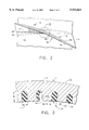
FIG. 2 is a radial sectional view through a mid-span portion of the airfoil illustrated in FIG. 1 taken along line 2--2.
FIG. 3 is an enlarged sectional view through the airfoil portion of the blade illustrated in FIG. 2 within the dasher circle labeled 3.
DESCRIPTION OF THE PREFERRED EMBODIMENT(S)
Illustrated in FIG. 1 is one of several exemplary gas turbine engine fan rotor blades 10 mounted to the perimeter of a rotor disk 12 shown in part. In accordance with the present invention, the blade 10 is configured as a hybrid blade including a metal airfoil 14 having a first or pressure side 16 which is generally concave, and a circumferentially opposite second or suction side 18 which is generally convex. The first and second sides or surfaces 16,18 extend radially along the span or longitudinal axis A of the airfoil 14 between a radially inner root 20 and an opposite radially outer tip 22.
The first and second sides also extend axially or laterally along the chord of the airfoil between a forward or leading edge 24 of the airfoil and an axially opposite aft or trailing edge 26. Ambient air 28 flows over the two airfoil sides from the leading edge to the trailing edge during operation and is pressurized by the airfoil in a conventional manner for producing propulsion thrust during operation for powering an aircraft in flight.
Although the airfoil 14 may be integrally or directly mounted to the rotor disk 12 in a one piece assembly known as a blisk, in the exemplary embodiment illustrated in FIG. 1 each of the airfoils 14 is removably attached to the disk 12 in a conventional manner. More specifically, the blade 10 further includes an integral metal shank 30 joined integrally with the airfoil root 20 for mounting the blade to the rotor disk 12. This is effected using a conventional metal dovetail 32 joined integrally with the shank 30 for mounting the blade in a complementary dovetail slot 12a in the rotor disk. The airfoil 14, shank 30, and dovetail 32 may initially be formed as a one-piece or unitary metal structure such as by forging. A suitable metal for the fan blade 10 is Titanium, for example.
The dovetail 32 is typically an axial-entry dovetail which is captured in a complementary axial dovetail slot 12a in the perimeter of the rotor disk 12. The shank 30 provides a structural transition from the dovetail 32 to the aerodynamic airfoil 14, and is typically not an aerodynamic member itself. The shank 30 is typically hidden from the airflow 28 by a suitable flow bounding platform 34 (shown in part) disposed at the airfoil root 20 either integrally therewith or as separately mounted platforms between adjacent ones of the blades 10 in a conventional manner.
In accordance with a preferred embodiment of the present invention, the airfoil 14 further includes a plurality of fine striations 36 spaced laterally apart between the leading and trailing edges 24,26 in the airfoil first side 16, which extend radially or longitudinally between the root 20 and the tip 22. A viscoelastic filler material 38 is suitably bonded in the striations 36 for damping primarily torsional vibration of the airfoil 14 during operation.
The striations 36 and filler 38 are illustrated in more particularity in FIGS. 2 and 3. The fine striations 36, or alternatively crenulations, define longitudinally or radially extending grooves 36a, as shown in FIG. 3, which extend transversely in depth B in the airfoil first side 16 toward the airfoil second side 18. The grooves 36a are separated laterally or axially by corresponding ribs 36b which extend longitudinally or radially between the root 20 and the tip 22 as illustrated in FIG. 1.
The striations 36 are specifically sized and configured in accordance with the present invention for placing the viscoelastic filler 38 in a location where it will be subjected to maximum shear strains generated by the torsional modes of vibration of the airfoil so that maximum damping thereof may be effected. As shown in FIG. 3, both the grooves 36a and corresponding ribs 36b are laterally thin for reducing weight and maximizing shear strain in the filler 38 and maximizing damping of torsional vibration of the airfoil 14.
Since shear strain due to bending or torsion are different, the striations 36 must be preferentially sized and configured to maximize shear strain in the filler 38 during the torsional modes as opposed to the bending mode. Torsional vibration of the airfoil 14 effects oscillatory twisting of the airfoil around the longitudinal axis A illustrated in FIG. 1. The corresponding shear strains developed by torsion are maximum along the outer surface of the airfoil 14 as opposed to the inner or center regions thereof. The grooves 36a illustrated in FIG. 3 therefore preferably extend only in part through the airfoil up to about mid-thickness thereof for maximizing torsion generated shear strain in the filler 38. The depth B of the individual grooves 36a may vary as desired up to about half of the airfoil thickness for maximizing damping effectiveness.
The grooves 36a and ribs 36b are relatively thin as compared to the maximum thickness T of the airfoil 14 at each radial section to ensure that torsional shear strain is effected in each of the ribs 36b for correspondingly deforming the filler 38 to effect damping. If the grooves 36a are excessively wide, the adjacent ribs will not effectively induce shear strain in the filler.
As shown in FIG. 3, the individual grooves 36a have a width C and extend in depth B to a suitable fillet radius at the base thereof for reducing stress concentration. In a preferred embodiment, the width C of each groove 36a is made as small as practical, or minimized, for maximizing the shear strain developed between adjacent ribs 36b for having maximum damping effect on the filler 38 bonded in the grooves 36a. The groove width C is preferably substantially less than the thickness T of the corresponding airfoil sections for suitable thinness. For example, the groove width C may be in the range of T/2 to T/10.
The width D of the ribs 36b is also relatively small, and generally greater than or equal to the width C of the groove 36a for maximizing the number of grooves 36a and filler 38 therein, with a suitable number of ribs 36b for effectively carrying torsion loads in shear during operation. The rib width D is also preferably less than the thickness T of the corresponding airfoil sections for suitable thinness, and for example may be about T/2. The pairs of thin grooves 36a and ribs 36b therefore collectively define correspondingly fine striations 36 whose pair width is also preferably less than the thickness T of the airfoil sections.
Any suitable viscoelastic filler material 38 may be used in the grooves 36a and may be suitably molded and heat cured therein to complete the desired aerodynamic profile of the airfoil 14 along the first side 16 thereof. The filler 38 may be a suitable rubber material bonded in the grooves using a suitable adhesive such as an epoxy adhesive designated 2216 under the Scotch Weld trade name available from the 3M Company of Minnesota.
As illustrated in FIGS. 1 and 2, the striations 36 are preferably disposed solely in the mid-chord region of the airfoil 14 and spaced laterally from both leading and trailing edges 24,26 to most effectively position the ribs 36b and filler 38 in the region subject to highest shear strain during torsional vibration. The striations 36 preferably terminate below the airfoil tip 22 and above the airfoil root 20 so that a continuous perimeter of metal remains around the striation group in the airfoil first side 16.
The striations 36 illustrated in FIG. 1 preferably cover the airfoil first side 16 laterally between the leading and trailing edges 24,26 and longitudinally between the root 20 and the tip 22 in a generally rectangular profile or array for maximizing torsional shear strain in the filler 38. Since the striations 36 are therefore placed in the region of the airfoil mid-chord, the leading and trailing edges remain solid metal for a significant axial extent for maintaining effective strength and resistance against foreign object damage due to bird strikes for example. The striations 36 include relatively shallow grooves within the thicker mid-chord region of the airfoil 14 which maintains substantial structural integrity of the airfoil 14 while providing enhanced torsional damping thereof.
The grooves 36a are filled with low density filler 38 and effectively reduce the overall weight of the higher density metal airfoil 14, which in turn reduces the centrifugal loads which must be accommodated by the airfoil 18 during operation. A significant weight saving may be obtained with the striations 36 while integrating significant amounts of damping.
Each of the striations 36 as illustrated in FIG. 1 has a corresponding length E which may be selected as desired for the specific mode shape being damped. For example, the striations 36 are preferably parallel to each other, and are continuous between the root 20 and the tip 22 over their entire length E without interruption or discontinuity in the grooves 36a and ribs 36b thereof. The striations 36 are also preferably substantially parallel to the leading and trailing edges 24,26 for being disposed in the generally radial direction relative to the centerline axis of the rotor disk 12. In this way, the grooves 36a do not introduce significant stress concentrations under the substantial centrifugal forces generated during operation which act along the radial or longitudinal axis of the airfoil.
In this preferred embodiment, the radially oriented ribs 36b experience relative radial elastic deformation or strain between the ribs during torsional vibratory response of the airfoil 14 for generating significant shear strain in the filler 38, which in turn maximizes the damping effectiveness of the filler 38 under such strain.
The striations 36 are preferably disposed in the airfoil first side 16 which is generally concave, which therefore maximizes the resulting strength and bending moments of inertia of the airfoil sections. Alternatively, the striations 36 may be disposed in the airfoil convex second side 18 if desired for specific applications.
Although the striations 36 are illustrated in the preferred embodiment in primarily only a radial orientation along the airfoil 14, the angular orientation thereof may be varied as desired for further maximizing effective damping of the airfoil in torsion modes in particular. Alternatively, the orientation of the striations 36 may be varied to maximize damping for other modes of vibration as desired. The number of grooves, width of the grooves and ribs, and radial extent of the grooves may also be varied to optimize the damping for a particular blade design. Although the specific configuration of the striations 36 illustrated in FIG. 1 enhance effective damping in torsional modes of vibration, damping may also be effected for other modes of vibration including flexural modes. For example, the airfoil 14 is also subject to stripe modes of vibration having two or more nodal lines, effectively dampened by the striations 36.
While there have been described herein what are considered to be preferred and exemplary embodiments of the present invention, other modifications of the invention shall be apparent to those skilled in the art from the teachings herein, and it is, therefore, desired to be secured in the appended claims all such modifications as fall within the true spirit and scope of the invention.
Accordingly, what is desired to be secured by Letters Patent of the United States is the invention as defined and differentiated in the following claims:

Claims (10)

We claim:
1. A gas turbine engine fan blade comprising:
a metal airfoil having first and second opposite sides extending longitudinally between a root and a tip, and laterally between a leading edge and a trailing edge for pressurizing air channeled thereover;
a plurality of fine striations spaced apart between said leading and trailing edges in said airfoil first side, and extending between said root and said tip; and
a viscoelastic filler bonded in said striations for damping vibration of said airfoil.
2. A blade according to claim 1 wherein said striations define grooves extending transversely into said airfoil first side toward said airfoil second side, and separated laterally by corresponding ribs.
3. A blade according to claim 2 wherein said grooves are laterally thin for maximizing shear strain in said filler for damping said airfoil vibration.
4. A blade according to claim 3 wherein said grooves extend only in part through said airfoil up to about mid-thickness thereof.
5. A blade according to claim 4 wherein said striations are disposed solely in a mid-chord region of said airfoil spaced laterally from both said leading and trailing edges.
6. A blade according to claim 5 wherein said striations extend longitudinally and terminate below said airfoil tip and above said airfoil root.
7. A blade according to claim 4 wherein said striations are parallel to each other and continuous between said root and said tip.
8. A blade according to claim 7 wherein said striations are substantially parallel to said leading and trailing edges.
9. A blade according to claim 8 wherein said striations cover said airfoil first side laterally between said leading and trailing edges and longitudinally between said root and tip in a rectangular array for maximizing shear strain in said filler for damping torsional vibration of said airfoil.
10. A blade according to claim 4 wherein said airfoil first side is generally concave.
US08/995,979 1997-12-22 1997-12-22 Striated hybrid blade Expired - Fee Related US5913661A (en)

Priority Applications (4)

Application Number Priority Date Filing Date Title
US08/995,979 US5913661A (en) 1997-12-22 1997-12-22 Striated hybrid blade
JP10298996A JPH11201089A (en) 1997-12-22 1998-10-21 Hybrid blade provided with groove
EP98308625A EP0924380B1 (en) 1997-12-22 1998-10-21 Striated turbomachine blade
DE69812051T DE69812051D1 (en) 1997-12-22 1998-10-21 Turbomachine blade with grooves

Applications Claiming Priority (1)

Application Number Priority Date Filing Date Title
US08/995,979 US5913661A (en) 1997-12-22 1997-12-22 Striated hybrid blade

Publications (1)

Publication Number Publication Date
US5913661A true US5913661A (en) 1999-06-22

Family

ID=25542384

Family Applications (1)

Application Number Title Priority Date Filing Date
US08/995,979 Expired - Fee Related US5913661A (en) 1997-12-22 1997-12-22 Striated hybrid blade

Country Status (4)

Country Link
US (1) US5913661A (en)
EP (1) EP0924380B1 (en)
JP (1) JPH11201089A (en)
DE (1) DE69812051D1 (en)

Cited By (18)

* Cited by examiner, † Cited by third party
Publication number Priority date Publication date Assignee Title
US20020090302A1 (en) * 2001-01-11 2002-07-11 Norris Jennifer M. Turbomachine blade
US6454536B1 (en) * 2000-02-09 2002-09-24 General Electric Company Adhesion enhancers to promote bonds of improved strength between elastomers metals in lightweight aircraft fan blades
US20040018091A1 (en) * 2002-07-26 2004-01-29 Rongong Jem A. Turbomachine blade
GB2397257A (en) * 2003-01-16 2004-07-21 Rolls Royce Plc Article provided with a vibration damping coating
US20050214505A1 (en) * 2004-03-23 2005-09-29 Rolls-Royce Plc Article having a vibration damping coating and a method of applying a vibration damping coating to an article
US20080232971A1 (en) * 2006-08-23 2008-09-25 Siemens Aktiengesellschaft Coated turbine blade
US20090074586A1 (en) * 2007-09-13 2009-03-19 Snecma Damping device for composite blade
US20100232970A1 (en) * 2006-05-26 2010-09-16 Ihi Corporation Fan rotating blade for turbofan engine
US20100232974A1 (en) * 2009-03-12 2010-09-16 Snecma Blade made of composite material comprising a damping device
US20100266415A1 (en) * 2009-04-16 2010-10-21 United Technologies Corporation Hybrid structure fan blade
US20120324901A1 (en) * 2011-06-23 2012-12-27 United Technologies Corporation Tandem fan-turbine rotor for a tip turbine engine
DE102015203868A1 (en) 2015-03-04 2016-09-08 Rolls-Royce Deutschland Ltd & Co Kg Fan blade for a propulsion system
US10677068B2 (en) * 2018-01-18 2020-06-09 Raytheon Technologies Corporation Fan blade with filled pocket
US20210123347A1 (en) * 2019-10-23 2021-04-29 Rolls-Royce Corporation Gas turbine engine blades with airfoil plugs for selected tuning
US10995631B2 (en) * 2019-04-01 2021-05-04 Pratt & Whitney Canada Corp. Method of shedding ice and fan blade
US11015462B2 (en) * 2018-05-22 2021-05-25 Safran Aircraft Engines Blade body and a blade made of composite material having fiber reinforcement made up both of three-dimensional weaving and also of short fibers, and method of fabrication
US11572796B2 (en) 2020-04-17 2023-02-07 Raytheon Technologies Corporation Multi-material vane for a gas turbine engine
US11795831B2 (en) 2020-04-17 2023-10-24 Rtx Corporation Multi-material vane for a gas turbine engine

Families Citing this family (5)

* Cited by examiner, † Cited by third party
Publication number Priority date Publication date Assignee Title
US6338609B1 (en) * 2000-02-18 2002-01-15 General Electric Company Convex compressor casing
DE10301755A1 (en) * 2003-01-18 2004-07-29 Rolls-Royce Deutschland Ltd & Co Kg Fan blade for a gas turbine engine
EP1640562A1 (en) * 2004-09-23 2006-03-29 Siemens Aktiengesellschaft Frequency tuning method of a turbine blade and turbine blade
GB2450936B (en) * 2007-07-13 2010-01-20 Rolls Royce Plc Bladed rotor balancing
US20130078103A1 (en) * 2011-09-23 2013-03-28 Christopher S. McKaveney Hollow fan blade rib geometry

Citations (10)

* Cited by examiner, † Cited by third party
Publication number Priority date Publication date Assignee Title
US2412615A (en) * 1943-04-16 1946-12-17 Gen Electric Bladed machine element
US2933286A (en) * 1954-09-15 1960-04-19 Gen Electric Damping turbine buckets
US3294366A (en) * 1965-04-20 1966-12-27 Rolls Royce Blades for gas turbine engines
US3796513A (en) * 1972-06-19 1974-03-12 Westinghouse Electric Corp High damping blades
US4118147A (en) * 1976-12-22 1978-10-03 General Electric Company Composite reinforcement of metallic airfoils
US4178667A (en) * 1978-03-06 1979-12-18 General Motors Corporation Method of controlling turbomachine blade flutter
FR2695163A1 (en) * 1992-09-02 1994-03-04 Snecma Hollow vane for gas turbine rotor - has one-piece body with apertures closed by plug sections
US5295789A (en) * 1992-03-04 1994-03-22 Societe Nationale D'etude Et De Construction De Moteurs D'aviation "Snecma" Turbomachine flow-straightener blade
US5634771A (en) * 1995-09-25 1997-06-03 General Electric Company Partially-metallic blade for a gas turbine
US5655883A (en) * 1995-09-25 1997-08-12 General Electric Company Hybrid blade for a gas turbine

Family Cites Families (2)

* Cited by examiner, † Cited by third party
Publication number Priority date Publication date Assignee Title
US3357850A (en) * 1963-05-09 1967-12-12 Gen Electric Vibration damping turbomachinery blade
US5947688A (en) * 1997-12-22 1999-09-07 General Electric Company Frequency tuned hybrid blade

Patent Citations (11)

* Cited by examiner, † Cited by third party
Publication number Priority date Publication date Assignee Title
US2412615A (en) * 1943-04-16 1946-12-17 Gen Electric Bladed machine element
US2933286A (en) * 1954-09-15 1960-04-19 Gen Electric Damping turbine buckets
US3294366A (en) * 1965-04-20 1966-12-27 Rolls Royce Blades for gas turbine engines
DE1628355A1 (en) * 1965-04-20 1970-10-15 Rolls Royce Compressor blade for gas turbine jet engines
US3796513A (en) * 1972-06-19 1974-03-12 Westinghouse Electric Corp High damping blades
US4118147A (en) * 1976-12-22 1978-10-03 General Electric Company Composite reinforcement of metallic airfoils
US4178667A (en) * 1978-03-06 1979-12-18 General Motors Corporation Method of controlling turbomachine blade flutter
US5295789A (en) * 1992-03-04 1994-03-22 Societe Nationale D'etude Et De Construction De Moteurs D'aviation "Snecma" Turbomachine flow-straightener blade
FR2695163A1 (en) * 1992-09-02 1994-03-04 Snecma Hollow vane for gas turbine rotor - has one-piece body with apertures closed by plug sections
US5634771A (en) * 1995-09-25 1997-06-03 General Electric Company Partially-metallic blade for a gas turbine
US5655883A (en) * 1995-09-25 1997-08-12 General Electric Company Hybrid blade for a gas turbine

Non-Patent Citations (6)

* Cited by examiner, † Cited by third party
Title
(Docket RD 24735) Patent application Serial No. 08/593,757, filed Jan. 29, 1996. *
(Docket RD 24978) Patent application Serial No. 08/650,278, filed May 20, 1996. *
(Docket RD 25135) Patent application Serial No. 08/837,880, filed Apr. 25, 1997. *
(Docket RD-24735) Patent application Serial No. 08/593,757, filed Jan. 29, 1996.
(Docket RD-24978) Patent application Serial No. 08/650,278, filed May 20, 1996.
(Docket RD-25135) Patent application Serial No. 08/837,880, filed Apr. 25, 1997.

Cited By (30)

* Cited by examiner, † Cited by third party
Publication number Priority date Publication date Assignee Title
US6454536B1 (en) * 2000-02-09 2002-09-24 General Electric Company Adhesion enhancers to promote bonds of improved strength between elastomers metals in lightweight aircraft fan blades
US20020090302A1 (en) * 2001-01-11 2002-07-11 Norris Jennifer M. Turbomachine blade
US6669447B2 (en) * 2001-01-11 2003-12-30 Rolls-Royce Plc Turbomachine blade
US7311500B2 (en) * 2002-07-26 2007-12-25 Rolls-Royce Plc Turbomachine blade
US20040018091A1 (en) * 2002-07-26 2004-01-29 Rongong Jem A. Turbomachine blade
GB2397257A (en) * 2003-01-16 2004-07-21 Rolls Royce Plc Article provided with a vibration damping coating
US20050214505A1 (en) * 2004-03-23 2005-09-29 Rolls-Royce Plc Article having a vibration damping coating and a method of applying a vibration damping coating to an article
US8007244B2 (en) 2004-03-23 2011-08-30 Rolls-Royce Plc Article having a vibration damping coating and a method of applying a vibration damping coating to an article
US7445685B2 (en) 2004-03-23 2008-11-04 Rolls-Royce Plc Article having a vibration damping coating and a method of applying a vibration damping coating to an article
US8186962B2 (en) * 2006-05-26 2012-05-29 Ihi Corporation Fan rotating blade for turbofan engine
US20100232970A1 (en) * 2006-05-26 2010-09-16 Ihi Corporation Fan rotating blade for turbofan engine
US20080232971A1 (en) * 2006-08-23 2008-09-25 Siemens Aktiengesellschaft Coated turbine blade
US8075279B2 (en) * 2006-08-23 2011-12-13 Siemens Aktiengesellschaft Coated turbine blade
US8061997B2 (en) * 2007-09-13 2011-11-22 Snecma Damping device for composite blade
US20090074586A1 (en) * 2007-09-13 2009-03-19 Snecma Damping device for composite blade
US20100232974A1 (en) * 2009-03-12 2010-09-16 Snecma Blade made of composite material comprising a damping device
US8500410B2 (en) * 2009-03-12 2013-08-06 Snecma Blade made of composite material comprising a damping device
US20100266415A1 (en) * 2009-04-16 2010-10-21 United Technologies Corporation Hybrid structure fan blade
US8083489B2 (en) * 2009-04-16 2011-12-27 United Technologies Corporation Hybrid structure fan blade
US20120324901A1 (en) * 2011-06-23 2012-12-27 United Technologies Corporation Tandem fan-turbine rotor for a tip turbine engine
US10125616B2 (en) 2015-03-04 2018-11-13 Rolls-Royce Deutschland Ltd & Co Kg Fan blade for an aircraft engine
EP3067519A1 (en) 2015-03-04 2016-09-14 Rolls-Royce Deutschland Ltd & Co KG Fan blade for a flight drive
DE102015203868A1 (en) 2015-03-04 2016-09-08 Rolls-Royce Deutschland Ltd & Co Kg Fan blade for a propulsion system
US10677068B2 (en) * 2018-01-18 2020-06-09 Raytheon Technologies Corporation Fan blade with filled pocket
US11015462B2 (en) * 2018-05-22 2021-05-25 Safran Aircraft Engines Blade body and a blade made of composite material having fiber reinforcement made up both of three-dimensional weaving and also of short fibers, and method of fabrication
US10995631B2 (en) * 2019-04-01 2021-05-04 Pratt & Whitney Canada Corp. Method of shedding ice and fan blade
US20210123347A1 (en) * 2019-10-23 2021-04-29 Rolls-Royce Corporation Gas turbine engine blades with airfoil plugs for selected tuning
US11220913B2 (en) * 2019-10-23 2022-01-11 Rolls-Royce Corporation Gas turbine engine blades with airfoil plugs for selected tuning
US11572796B2 (en) 2020-04-17 2023-02-07 Raytheon Technologies Corporation Multi-material vane for a gas turbine engine
US11795831B2 (en) 2020-04-17 2023-10-24 Rtx Corporation Multi-material vane for a gas turbine engine

Also Published As

Publication number Publication date
JPH11201089A (en) 1999-07-27
EP0924380A3 (en) 2000-02-23
DE69812051D1 (en) 2003-04-17
EP0924380B1 (en) 2003-03-12
EP0924380A2 (en) 1999-06-23

Similar Documents

Publication Publication Date Title
US5913661A (en) Striated hybrid blade
US5947688A (en) Frequency tuned hybrid blade
US6033186A (en) Frequency tuned hybrid blade
US6039542A (en) Panel damped hybrid blade
US5725354A (en) Forward swept fan blade
US6364616B1 (en) Submerged rib hybrid blade
EP2305954B1 (en) Internally damped blade
EP2589461B1 (en) Rotor blade with bonded cover
EP1617044B1 (en) Selectively thinned turbine blade
JP3989576B2 (en) Partially metal wings for gas turbines
JP3924333B2 (en) Composite blade
EP2372094B1 (en) Section of a gas turbine and method of damping blade vibration
US6508630B2 (en) Twisted stator vane
CA1270802A (en) Prop-fan with improved stability
CA1233126A (en) Gas turbine bladed disk assembly
US7458780B2 (en) Hollow fan blade for gas turbine engine
US7399159B2 (en) Detachable leading edge for airfoils
EP2607628A2 (en) Airfoils including compliant tip
UA57816C2 (en) Rotor with integral structure of the blade set
GB2431697A (en) Fan blade having maximum forward sweep at tip
US11725520B2 (en) Fan rotor for airfoil damping

Legal Events

Date Code Title Description
AS Assignment

Owner name: GENERAL ELECTRIC COMPANY, NEW YORK

Free format text: ASSIGNMENT OF ASSIGNORS INTEREST;ASSIGNORS:PANOVSKY, JOSEF;STEVENSON, JOSEPH T.;REEL/FRAME:008915/0540;SIGNING DATES FROM 19971204 TO 19971208

AS Assignment

Owner name: UNITED STATES OF AMERICA OFFICE OF NAVAL RESEARCH,

Free format text: CHANGE OF NAME;ASSIGNOR:GENERAL ELECTRIC COMPANY;REEL/FRAME:009695/0022

Effective date: 19970508

REMI Maintenance fee reminder mailed
LAPS Lapse for failure to pay maintenance fees
STCH Information on status: patent discontinuation

Free format text: PATENT EXPIRED DUE TO NONPAYMENT OF MAINTENANCE FEES UNDER 37 CFR 1.362

FP Expired due to failure to pay maintenance fee

Effective date: 20030622