EP3067519A1 - Fan blade for a flight drive - Google Patents
Fan blade for a flight drive Download PDFInfo
- Publication number
- EP3067519A1 EP3067519A1 EP16155260.9A EP16155260A EP3067519A1 EP 3067519 A1 EP3067519 A1 EP 3067519A1 EP 16155260 A EP16155260 A EP 16155260A EP 3067519 A1 EP3067519 A1 EP 3067519A1
- Authority
- EP
- European Patent Office
- Prior art keywords
- blade
- elastomer layer
- fan blade
- fan
- suction side
- Prior art date
- Legal status (The legal status is an assumption and is not a legal conclusion. Google has not performed a legal analysis and makes no representation as to the accuracy of the status listed.)
- Granted
Links
Images


Classifications
-
- F—MECHANICAL ENGINEERING; LIGHTING; HEATING; WEAPONS; BLASTING
- F01—MACHINES OR ENGINES IN GENERAL; ENGINE PLANTS IN GENERAL; STEAM ENGINES
- F01D—NON-POSITIVE DISPLACEMENT MACHINES OR ENGINES, e.g. STEAM TURBINES
- F01D5/00—Blades; Blade-carrying members; Heating, heat-insulating, cooling or antivibration means on the blades or the members
- F01D5/12—Blades
- F01D5/28—Selecting particular materials; Particular measures relating thereto; Measures against erosion or corrosion
-
- F—MECHANICAL ENGINEERING; LIGHTING; HEATING; WEAPONS; BLASTING
- F01—MACHINES OR ENGINES IN GENERAL; ENGINE PLANTS IN GENERAL; STEAM ENGINES
- F01D—NON-POSITIVE DISPLACEMENT MACHINES OR ENGINES, e.g. STEAM TURBINES
- F01D5/00—Blades; Blade-carrying members; Heating, heat-insulating, cooling or antivibration means on the blades or the members
- F01D5/12—Blades
- F01D5/14—Form or construction
- F01D5/16—Form or construction for counteracting blade vibration
-
- F—MECHANICAL ENGINEERING; LIGHTING; HEATING; WEAPONS; BLASTING
- F01—MACHINES OR ENGINES IN GENERAL; ENGINE PLANTS IN GENERAL; STEAM ENGINES
- F01D—NON-POSITIVE DISPLACEMENT MACHINES OR ENGINES, e.g. STEAM TURBINES
- F01D5/00—Blades; Blade-carrying members; Heating, heat-insulating, cooling or antivibration means on the blades or the members
- F01D5/12—Blades
- F01D5/28—Selecting particular materials; Particular measures relating thereto; Measures against erosion or corrosion
- F01D5/282—Selecting composite materials, e.g. blades with reinforcing filaments
-
- F—MECHANICAL ENGINEERING; LIGHTING; HEATING; WEAPONS; BLASTING
- F01—MACHINES OR ENGINES IN GENERAL; ENGINE PLANTS IN GENERAL; STEAM ENGINES
- F01D—NON-POSITIVE DISPLACEMENT MACHINES OR ENGINES, e.g. STEAM TURBINES
- F01D5/00—Blades; Blade-carrying members; Heating, heat-insulating, cooling or antivibration means on the blades or the members
- F01D5/34—Rotor-blade aggregates of unitary construction, e.g. formed of sheet laminae
-
- F—MECHANICAL ENGINEERING; LIGHTING; HEATING; WEAPONS; BLASTING
- F04—POSITIVE - DISPLACEMENT MACHINES FOR LIQUIDS; PUMPS FOR LIQUIDS OR ELASTIC FLUIDS
- F04D—NON-POSITIVE-DISPLACEMENT PUMPS
- F04D29/00—Details, component parts, or accessories
- F04D29/02—Selection of particular materials
- F04D29/023—Selection of particular materials especially adapted for elastic fluid pumps
-
- F—MECHANICAL ENGINEERING; LIGHTING; HEATING; WEAPONS; BLASTING
- F04—POSITIVE - DISPLACEMENT MACHINES FOR LIQUIDS; PUMPS FOR LIQUIDS OR ELASTIC FLUIDS
- F04D—NON-POSITIVE-DISPLACEMENT PUMPS
- F04D29/00—Details, component parts, or accessories
- F04D29/26—Rotors specially for elastic fluids
- F04D29/32—Rotors specially for elastic fluids for axial flow pumps
- F04D29/321—Rotors specially for elastic fluids for axial flow pumps for axial flow compressors
- F04D29/324—Blades
-
- F—MECHANICAL ENGINEERING; LIGHTING; HEATING; WEAPONS; BLASTING
- F04—POSITIVE - DISPLACEMENT MACHINES FOR LIQUIDS; PUMPS FOR LIQUIDS OR ELASTIC FLUIDS
- F04D—NON-POSITIVE-DISPLACEMENT PUMPS
- F04D29/00—Details, component parts, or accessories
- F04D29/26—Rotors specially for elastic fluids
- F04D29/32—Rotors specially for elastic fluids for axial flow pumps
- F04D29/325—Rotors specially for elastic fluids for axial flow pumps for axial flow fans
-
- F—MECHANICAL ENGINEERING; LIGHTING; HEATING; WEAPONS; BLASTING
- F04—POSITIVE - DISPLACEMENT MACHINES FOR LIQUIDS; PUMPS FOR LIQUIDS OR ELASTIC FLUIDS
- F04D—NON-POSITIVE-DISPLACEMENT PUMPS
- F04D29/00—Details, component parts, or accessories
- F04D29/26—Rotors specially for elastic fluids
- F04D29/32—Rotors specially for elastic fluids for axial flow pumps
- F04D29/38—Blades
- F04D29/388—Blades characterised by construction
-
- F—MECHANICAL ENGINEERING; LIGHTING; HEATING; WEAPONS; BLASTING
- F04—POSITIVE - DISPLACEMENT MACHINES FOR LIQUIDS; PUMPS FOR LIQUIDS OR ELASTIC FLUIDS
- F04D—NON-POSITIVE-DISPLACEMENT PUMPS
- F04D29/00—Details, component parts, or accessories
- F04D29/66—Combating cavitation, whirls, noise, vibration or the like; Balancing
- F04D29/661—Combating cavitation, whirls, noise, vibration or the like; Balancing especially adapted for elastic fluid pumps
- F04D29/668—Combating cavitation, whirls, noise, vibration or the like; Balancing especially adapted for elastic fluid pumps damping or preventing mechanical vibrations
-
- F—MECHANICAL ENGINEERING; LIGHTING; HEATING; WEAPONS; BLASTING
- F05—INDEXING SCHEMES RELATING TO ENGINES OR PUMPS IN VARIOUS SUBCLASSES OF CLASSES F01-F04
- F05D—INDEXING SCHEME FOR ASPECTS RELATING TO NON-POSITIVE-DISPLACEMENT MACHINES OR ENGINES, GAS-TURBINES OR JET-PROPULSION PLANTS
- F05D2220/00—Application
- F05D2220/30—Application in turbines
- F05D2220/36—Application in turbines specially adapted for the fan of turbofan engines
-
- F—MECHANICAL ENGINEERING; LIGHTING; HEATING; WEAPONS; BLASTING
- F05—INDEXING SCHEMES RELATING TO ENGINES OR PUMPS IN VARIOUS SUBCLASSES OF CLASSES F01-F04
- F05D—INDEXING SCHEME FOR ASPECTS RELATING TO NON-POSITIVE-DISPLACEMENT MACHINES OR ENGINES, GAS-TURBINES OR JET-PROPULSION PLANTS
- F05D2230/00—Manufacture
- F05D2230/20—Manufacture essentially without removing material
- F05D2230/25—Manufacture essentially without removing material by forging
-
- F—MECHANICAL ENGINEERING; LIGHTING; HEATING; WEAPONS; BLASTING
- F05—INDEXING SCHEMES RELATING TO ENGINES OR PUMPS IN VARIOUS SUBCLASSES OF CLASSES F01-F04
- F05D—INDEXING SCHEME FOR ASPECTS RELATING TO NON-POSITIVE-DISPLACEMENT MACHINES OR ENGINES, GAS-TURBINES OR JET-PROPULSION PLANTS
- F05D2230/00—Manufacture
- F05D2230/90—Coating; Surface treatment
-
- F—MECHANICAL ENGINEERING; LIGHTING; HEATING; WEAPONS; BLASTING
- F05—INDEXING SCHEMES RELATING TO ENGINES OR PUMPS IN VARIOUS SUBCLASSES OF CLASSES F01-F04
- F05D—INDEXING SCHEME FOR ASPECTS RELATING TO NON-POSITIVE-DISPLACEMENT MACHINES OR ENGINES, GAS-TURBINES OR JET-PROPULSION PLANTS
- F05D2240/00—Components
- F05D2240/20—Rotors
- F05D2240/30—Characteristics of rotor blades, i.e. of any element transforming dynamic fluid energy to or from rotational energy and being attached to a rotor
- F05D2240/306—Characteristics of rotor blades, i.e. of any element transforming dynamic fluid energy to or from rotational energy and being attached to a rotor related to the suction side of a rotor blade
-
- F—MECHANICAL ENGINEERING; LIGHTING; HEATING; WEAPONS; BLASTING
- F05—INDEXING SCHEMES RELATING TO ENGINES OR PUMPS IN VARIOUS SUBCLASSES OF CLASSES F01-F04
- F05D—INDEXING SCHEME FOR ASPECTS RELATING TO NON-POSITIVE-DISPLACEMENT MACHINES OR ENGINES, GAS-TURBINES OR JET-PROPULSION PLANTS
- F05D2300/00—Materials; Properties thereof
- F05D2300/40—Organic materials
- F05D2300/43—Synthetic polymers, e.g. plastics; Rubber
-
- F—MECHANICAL ENGINEERING; LIGHTING; HEATING; WEAPONS; BLASTING
- F05—INDEXING SCHEMES RELATING TO ENGINES OR PUMPS IN VARIOUS SUBCLASSES OF CLASSES F01-F04
- F05D—INDEXING SCHEME FOR ASPECTS RELATING TO NON-POSITIVE-DISPLACEMENT MACHINES OR ENGINES, GAS-TURBINES OR JET-PROPULSION PLANTS
- F05D2300/00—Materials; Properties thereof
- F05D2300/50—Intrinsic material properties or characteristics
- F05D2300/501—Elasticity
-
- F—MECHANICAL ENGINEERING; LIGHTING; HEATING; WEAPONS; BLASTING
- F05—INDEXING SCHEMES RELATING TO ENGINES OR PUMPS IN VARIOUS SUBCLASSES OF CLASSES F01-F04
- F05D—INDEXING SCHEME FOR ASPECTS RELATING TO NON-POSITIVE-DISPLACEMENT MACHINES OR ENGINES, GAS-TURBINES OR JET-PROPULSION PLANTS
- F05D2300/00—Materials; Properties thereof
- F05D2300/50—Intrinsic material properties or characteristics
- F05D2300/522—Density
-
- F—MECHANICAL ENGINEERING; LIGHTING; HEATING; WEAPONS; BLASTING
- F05—INDEXING SCHEMES RELATING TO ENGINES OR PUMPS IN VARIOUS SUBCLASSES OF CLASSES F01-F04
- F05D—INDEXING SCHEME FOR ASPECTS RELATING TO NON-POSITIVE-DISPLACEMENT MACHINES OR ENGINES, GAS-TURBINES OR JET-PROPULSION PLANTS
- F05D2300/00—Materials; Properties thereof
- F05D2300/60—Properties or characteristics given to material by treatment or manufacturing
- F05D2300/615—Filler
-
- Y—GENERAL TAGGING OF NEW TECHNOLOGICAL DEVELOPMENTS; GENERAL TAGGING OF CROSS-SECTIONAL TECHNOLOGIES SPANNING OVER SEVERAL SECTIONS OF THE IPC; TECHNICAL SUBJECTS COVERED BY FORMER USPC CROSS-REFERENCE ART COLLECTIONS [XRACs] AND DIGESTS
- Y02—TECHNOLOGIES OR APPLICATIONS FOR MITIGATION OR ADAPTATION AGAINST CLIMATE CHANGE
- Y02T—CLIMATE CHANGE MITIGATION TECHNOLOGIES RELATED TO TRANSPORTATION
- Y02T50/00—Aeronautics or air transport
- Y02T50/60—Efficient propulsion technologies, e.g. for aircraft
Definitions
- the invention relates to a fan blade for a flight drive according to the preamble of claim 1.
- Aero engines must be able to withstand a fan blade loss.
- a fan blade loss occurs when a fan blade breaks and blade segments separate, which can cause significant damage to the engine and the entire aircraft.
- the proportionately radially outward mass of the lost fan blade causes high impact forces in the fan case.
- a relatively heavy fan housing, a strong front bearing structure and a relatively heavy fan rotor are required. These cause high imbalance forces introduced into the aircraft-side engine mount, which in turn leads to the requirement to make the engine mount relatively heavy and massive.
- honeycomb fills according to the US 2014/0072427 A1 are introduced into suction recesses of fan blades, unsuitable for damping against blade vibrations and prone to cracking during overstretching, for example in the case of a bird strike.
- the main body of the fan blade introduced grooves corresponding to US 5,913,661 A
- the solution according to the invention is characterized in that the fan blade has a large-area elastomer layer which forms at least 20% of the surface of the suction side of the fan blade and whose thickness increases in the radial direction outwardly at least in sections.
- the elastomer layer is formed in one piece and contiguous from a full elastomer and not provided with cavities.
- the at least partial formation of the suction side of the blade by an elastomer layer has the advantage that the weight of the fan blade is reduced by the elastomer layer due to its comparatively low density, which leads to a reduction of the impact load and the balancing load in the event of fan blade loss.
- a reduction of the impact load and the Umwuchtlast in the case of a fan blade loss of up to 30% can be achieved by the inventive solution.
- a further advantage in the use of a large-area elastomer layer is that the elastomer layer applied over a large area to the fan blade serves as a vibration damper against blade vibrations, which are excited, for example, by engine vibrations and their frequency multiples.
- the vibration damping property is related to the elastomeric layer having a lower modulus of elasticity than the other blade material (typically a metal or metal alloy), so that other vibration characteristics are provided.
- a third advantage of the inventive arrangement of an elastomer on the suction side of the fan blade is that the separate application of a metal lid on the elastomer layer and thus the risk of cracking on the connection of such a metal lid with the Fanschaufel groundSystem in case of overstretching (for example Bird strike) can be avoided. It is provided that the elastomer is resistant to wear and accordingly suitable to form the suction side of the fan blade.
- the elastomer layer covers a proportion of 20% to 80%, in particular a proportion of 30% to 50% of the area of the suction side of the blade.
- the large-area elastomer layer forms a massive, homogeneous structure of an elastomer.
- the elastomer layer is not formed by separate items, but represents a single, coherent structure.
- the surface of the suction side of the blade to which the proportion of at least 20% refers becomes that area on the suction side of the blade viewed at the intended use of the blade in a fan gas or air flows past.
- the elastomer layer is spaced from the leading edge and / or spaced from the trailing edge formed on the suction side of the blade.
- there is a spacing to the leading edge as it must withstand a particular extent bombardment with particles or objects possibly located in the gas stream and is accordingly advantageously formed from a metal.
- a further embodiment of the invention provides that the elastomer layer is formed predominantly in the region of the blade on the suction side, which, relative to the total height of the blade, constitutes the radially outer half of the blade.
- the elastomer layer is thus provided predominantly in the radially outer region of the blade. This is of particular advantage since this reduces the weight of the fan blade in the radially outer region, which leads to a reduction of the impact load and the balancing load in the event of a fan blade loss.
- hybrid fan blades according to the invention in engines which hitherto use all-metal fan blades and in which the relatively high thickness of the outer portion of the fan blade is necessary to achieve a good aerodynamic profile, but does not contribute to the same extent to the strength of the all-metal fan blade ,
- Here can be saved by attaching a large-area elastomer layer on the suction side of the blade in particular weight. It has been found that the full thickness of the fan blade at the radially outer end for the blade strength is not needed and the all-metallic blade material can be substantially replaced by the elastomer layer according to the invention.
- the elastomer layer extends to the blade tip of the blade. Because the elastomer layer expands more radially under centrifugal force due to their lower modulus of elasticity, for example, about 20 to 30 N / mm 2 in comparison to titanium with a modulus of elasticity of 105,000 N / mm 2, the elastomer layer on the Fanschaufelspitze against the metal is Body radially shortened. This avoids that the elastomer layer starts radially under centrifugal expansion at the fan housing and is thereby damaged. Alternatively, the elastomer layer terminates at a distance from the blade tip, the for example, in the range between 0.5 mm and 5 cm. As a result, it can be prevented, for example, that the elastomer layer expands beyond the blade tip during operation due to the centrifugal force.
- the elastomer layer is formed on the suction side substantially U-shaped, wherein the open end of the U-shaped portion terminates at the blade tip or facing it. According to this embodiment, the elastomer layer thus begins on the suction side in a central region and widens with increasing radial height to the blade tip or to just before the blade tip.
- the elastomer layer in the region of the blade in which it is arranged has a proportion of the total thickness of the blade of up to 50%, up to 60%, up to 70% or up to 80%. having.
- the elastomer layer in the area of the blade in which the elastomer layer is provided, it can make up a substantial portion of the thickness of the blade, up to 80%.
- the thickness of the elastomer layer preferably increases continuously from radially inward to radially outward.
- the thickness of the elastomer layer increases at least in sections in the radial direction to the outside.
- the thickness of the elastomer layer thus increases either continuously with increasing radial height of the blade or, after it has reached a certain thickness, remains constant in its thickness.
- a large-area stiffness transition in the radial direction is provided which takes place continuously and steadily and does not involve any jumps in rigidity, as would occur, for example, in the case of axially extending ribs.
- the bucket becomes softer towards the outside. This improves the property of the elastomer layer to counteract blade vibration as a vibration damper.
- the thickness of the elastomeric layer which increases outward at least in sections, can be accompanied by a thickness of a metal main body of the fan blade which is outwardly at least partially or constantly decreasing, to which the elastomer layer is applied is.
- the proportion of metal on the fan blade decreases and the weight of the fan blade is increasingly reduced to a radially outer portion of the fan blade.
- the fan blade is formed according to an advantageous embodiment of the invention, apart from the elastomer layer as a one-piece, all-metal blade.
- the blade consists in this case of a blade body made of metal and the elastomer layer, which forms the surface of the suction side of the blade over a large area.
- the blade base body consists of a forged metal.
- the invention is by no means limited to the fact that the fan blade is formed in its main blade body as a forged blade.
- other manufacturing methods such as e.g. Metal powder injection molding and milling are used.
- the blade body does not necessarily have to be formed in one piece and solid.
- the blade base body is designed as a composite blade on the basis of carbon fibers.
- the weight of such Kompositfanschaufel can be reduced in the outer region by a suction side applied elastomer layer to reduce stresses in the blade root.
- a reduction of fan blade vibrations can be achieved by a blade damping means of the elastomer layer.
- a further embodiment of the invention provides that the blade material in the region which does not form the elastomer layer has a large-area recess. In the absence of the elastomer layer, this large-area recess is formed toward the suction side of the blade. The elastomer layer is applied to this large-area recess and completes in this way the fan blade.
- Such a large-area recess can be incorporated in the fan blade, for example, when forging the blade body.
- the introduction of the recess is carried out by milling or other machining methods after production of the blade body. After the elastomer layer is applied to the large-area recess, it can be provided that they is then milled to provide exactly the aerodynamically desired shape of the suction side.
- the elastomeric layer can be provided, for example, as an injection-molded part or by vulcanizing a prefabricated pad.
- the connection of the elastomer layer to the blade body follows, for example, by gluing.
- certain surface roughnesses of the blade main body are provided in the region of the recess and / or the elastomer layer.
- positive-locking connections can also be provided.
- the elastomeric layer may in principle be made of any elastomer, i. made of any dimensionally stable, elastically deformable plastic.
- the elastomer layer is formed, for example, from a fluorinated hydrocarbon, for example from fluororubber, especially copolymer, wherein the elastomer layer is applied according to an embodiment directly on the metallic body of the fan blade and crosslinked there, preferably crosslinked peroxide.
- Copolymer is characterized by its low-temperature flexibility and dimensional stability under pressure. Its low-temperature flexibility makes it well suited for cold ambient temperatures, for example in winter and at high altitudes. Furthermore, it gives the hybrid fan blade good resistance to major elastic deformations, especially bird strikes.
- the high dimensional stability under pressure load gives the hybrid fan blade a high dimensional stability of the aerodynamic profile and thus a high efficiency.
- the fan blade can be applied by injection molding or by vulcanizing prefabricated pads by means of gluing or vulcanization on the whole metal body.
- the crosslinking, vulcanization or bonding of prefabricated pads is done in one embodiment under pressure to achieve a better connection to the blade body.
- This can be achieved by one or more flexible or rigid moldings, by means of which or a prefabricated pad during crosslinking, vulcanizing or gluing with a sufficiently high pressure, for example in the range of 50 kPa to 1000 kPa, in particular in the range of 100 kPa to 200 kPa is pressed onto the blade body.
- the elastomer layer has a lower density than the blade main body. This applies both in the case that the blade body is massively formed of metal (for example made of titanium with a density of 4.50 g / cm 3 ), as well as for the case that the blade body is made in composite construction, in which case the Density typically is about 1.90 to 2.00 g / cm 3 .
- the density of the elastomer is at least a factor of 2 or at least a factor of 4 lower than the density of the blade body.
- the choice of material can be made such that the elastomer layer on its outer side (which forms the suction side of the fan blade) has a high abrasive wear resistance. This is achieved, for example, by the choice of an elastomer having a Shore A hardness of at least 50, in particular of at least 60, e.g. of at least 80.
- the invention further relates to a fan for a turbofan engine with a plurality of blades according to claim 1.
- Fan blades according to the present invention also include propeller blades.
- the FIG. 7 schematically shows a turbofan engine 1.
- the turbofan engine 1 includes a low pressure compressor 10 with a fan 11, a medium pressure compressor 20, a high pressure compressor 30, a combustion chamber 40, a high pressure turbine 50, a medium pressure turbine 60 and a low pressure turbine 70.
- the medium pressure compressor 20 and the high pressure compressor 30 have each have a plurality of compressor stages, each compressor stage comprising a rotor and a stator.
- the turbofan engine 1 comprises a low-pressure compressor, which is arranged in the core engine in front of the high-pressure compressor 30.
- the low-pressure compressor 10 comprises a fan 11 with fan blades 12, which are fastened to a fan disk 13.
- the low-pressure compressor 10 further includes a fan case 15.
- the turbofan engine forms a secondary flow channel or bypass channel 4 and a primary flow channel 3, which leads through the core engine. Air is sucked and accelerated by the fan 11, wherein two air streams are provided, a first air flow through the primary flow channel 3 and a second air flow through the secondary flow channel 4. In the secondary flow channel 4 while vanes 45 and / or struts can be arranged.
- the high-pressure turbine 50, the medium-pressure turbine 60 and the low-pressure turbine 70 respectively drive the high-pressure compressor 30, the medium-pressure compressor 20 and the fan 11 via a high-pressure shaft, a medium-pressure shaft and a low-pressure shaft.
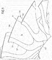
- FIG. 1 is a perspective view obliquely from the front of a plurality of fan blades 12 of a fan.
- Each fan blade 12 comprises a front edge 121, a trailing edge 122, a blade tip 123, a suction side 124 and a pressure side 125.
- a separate blade root is due to the BLISK design in the embodiment of FIG. 1 not provided. As for the FIG. 2 will be explained, however, the individual fan blades 12 may also be formed with a blade root.
- the fan blade 12 further comprises an elastomer layer 14 which is formed over a large area on the suction side 124 of the blade 12.
- a large-area arrangement of the elastomer layer 14 on the suction side of the blade 12 means that the elastomer layer occupies at least 20% of the area of the suction side 124 of the blade 12. Preferably, this percentage is greater and is for example in the range between 20% and 80%, in particular in the range between 30% and 50% of the area of the suction side of the blade 12.
- the elastomer layer 14 is, for example, a fluorinated hydrocarbon, in particular a fluororubber, which is distinguished by a high abrasive wear resistance and is therefore suitable for forming the suction side of the blade 12.
- the elastomer layer 14 is vulcanized onto the blade base material, for example, as described with reference to FIGS FIG. 3 will be explained.
- FIG. 2 shows an alternative embodiment of a fan blade 12.
- the fan blade 12 is intended for use with a plug fan.
- the fan blade 12 of the FIG. 2 a blade root 126, which can be plugged into a corresponding disc or other structure of the fan in a conventional manner.
- the connection of the fan blade 12 with the fan disk 13 does not matter in the context of the present invention.
- the Fan blade 12 also has an elastomer layer 14 which is arranged on the suction side 124 of the blade 12.
- the shape of the elastomer layer 14 will be described with reference to FIGS FIG. 2 explained in more detail. The explanations apply equally to the FIG. 1 in which the elastomeric layer 14 is partially obscured by other fan blades.
- the elastomeric layer 14 has a shape such that it is spaced from the leading edge 121 of the fan blade 12. Furthermore, the elastomer layer 14 is also spaced from the trailing edge 122 of the fan blade.
- the elastomer layer 14 forms a U-shaped region. It is accordingly bounded by a bent region 143, to which two legs 141, 142 adjoin in the radial direction, which delimit the elastomer layer 14 in the axial direction forwards and backwards.
- the elastomer layer 14 widens in the radial direction from a small axial extent in the bent region 143 to an increasing axial extent towards the blade edge 123.
- the blade 12 is formed in the regions which are not formed by the elastomer layer 14, by a blade body.
- This may be a one-piece, forged full metal, such as titanium.
- the blade base body can also be designed in composite construction, for example as a composite fan blade based on carbon fibers.
- the blade main body has a large-area recess or flattening. This is in the presentation of FIG. 3 which shows a view from the direction of the blade tip 123. Thereafter, a large-area recess 128 is introduced in the blade main body 127 to the suction side 124. This recess 128 can be incorporated, for example, in the forging of the blade body 127 in this. According to an alternative embodiment, the recess 128 is subsequently milled into the blade material, ground or introduced in any other way.
- the elastomer layer 14 is, for example, directly crosslinked as an injection molding compound on the all-metal body 127 in the injection mold or produced as a separate injection molded part and then glued into the recess 128.
- the elastomer layer 14 is provided by a prefabricated pad, which is vulcanized onto the recess 14. After attaching or securing the elastomer layer 14 in the recess 128 may be provided that the elastomer layer 14 is milled or ground to give her exactly the desired shape on the suction side of the blade 12.
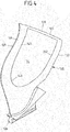
- FIG. 4 shows a modification of the blade of the FIG. 2
- the embodiment of FIG. 4 differs from the embodiment of FIG. 2 in that the elastomeric layer 14 does not extend to the blade tip 123, but an edge 129 remains between the blade tip 123 and the open end of the U-shaped elastomer layer 14.
- the width of the edge 129 may be, for example, between 5 mm and 5 cm.
- the thickness of the elastomer layer 14 varies in the radial direction and / or in the axial direction. This applies to all embodiments of the FIGS. 1 to 4 .
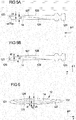
- the FIGS. 5A and 5B show the variation of the thickness d1 of the elastomer layer 14 in the longitudinal direction of the blade, ie in the radial direction r.
- the FIG. 5A shows an example of a longitudinal section through the blade of the Figures 1-3 and the FIG. 5B shows an example of a longitudinal section through the blade of FIG. 4 , Accordingly, extends in the FIG. 5A the elastomer layer 14 to the blade edge 123. In the FIG. 5B the edge 129 remains between the elastomer layer 14 and the blade edge 123.
- the thickness d1 of the elastomer layer 14 increases from a radially inward point (in the bent region 143) towards the blade tip 123, this being accompanied by a thickness d2 of the metallic base body 127 which constantly decreases toward the outside. This ensures that with increasing radius r the proportion of metal on the blade decreases and, accordingly, the weight of the blade is increasingly reduced to the radially outer portion of the blade.
- the continuous increase in the thickness d1 of the elastomer layer 14 towards the blade tip 123 causes a large-area transition of the rigidity of the blade in the radial direction r.
- the thickness d2 of the metallic blade main body 127 remaining adjacent to the blade tip 123 is sufficient to provide the necessary blade stability.
- the elastomer layer 14 tapers again in its radially outermost end region over the radial distance k, ie over the distance k it has a thickness d1 which decreases toward the blade edge 123, without the thickness d2 of the blade base body 127 increasing thereby. It is insofar an edge shortening of the elastomer layer 14 before. But this is only optional.
- FIG. 5B remains an edge 129 between the elastomer layer 14 and the blade edge 123. Also in the FIG. 5B reduces the thickness d1 of the elastomer layer 14 in its radially outermost end region, here with increasing thickness d2 of the blade body 127. Again, this is only optional.
- the thickness d1 of the elastomer layer 14 increases towards the blade tip 123 up to 80% of the total thickness of the blade 12.
- the thickness of the elastomer layer 14 at the radially outer end of the elastomer layer may be up to 4mm.
- FIG. 6 schematically shows a thickness distribution, showing a cross section through a blade 12, ie a section in the axial direction x and in the circumferential direction u and thereby perpendicular to the radial direction.
- the thickness d1 of the elastomer layer 14 decreases towards the leading edge 121 and the trailing edge 122.
- the thickness d1 of the elastomer layer is greatest and the thickness d2 of the blade main body 127 is only about 50% to 20%, preferably 20%, of the total thickness d3 of the blade 12.
- the dashed lines of the FIG. 6 indicate the thickness d1 of the elastomeric layer 14 for cuts at other radial heights. According to the FIG. 5 increases the thickness of the elastomer layer 14 with the radial blade extension. The FIG. 6 Thus, the solid line indicates the thickness of the elastomer layer 14 near the blade tip 123.
- a thickness distribution according to the FIG. 5 also in a different way than in FIG. 6 shown in the axial direction x can be realized.
- the thickness d1 of the elastomer layer 14 in the axial direction x is substantially constant or only slightly reduced at the transitions to the blade main body 127.
- the invention is not limited in its embodiment to the embodiments shown above, which are to be understood only as examples.
- the shape of the elastomer layer 14 is in the FIGS. 1 to 4 merely to be understood as an example.
- a large, continuous elastomer layer can also be provided in numerous other forms, for example circular, oval or rectangular.
- the shape of the blade is shown by way of example only, with the exact shape of the blade being immaterial to the present invention.
Abstract
Die Erfindung betrifft eine Fanschaufel (12) für einen Flugantrieb, die eine Vorderkante (121), eine Hinterkante (122), eine Saugseite (124), eine Druckseite (125) und eine Schaufelspitze (123) aufweist. Es ist vorgesehen, dass die Fanschaufel (12) eine großflächige Elastomerschicht (14) aufweist, die zumindest 20% der Oberfläche der Saugseite (124) der Fanschaufel (12) bildet und deren Dicke in radialer Richtung nach außen zumindest abschnittsweise zunimmt.The invention relates to a fan blade (12) for a propulsion system, which has a leading edge (121), a trailing edge (122), a suction side (124), a pressure side (125) and a blade tip (123). It is envisaged that the fan blade (12) has a large-area elastomer layer (14) which forms at least 20% of the surface of the suction side (124) of the fan blade (12) and whose thickness in the radial direction increases at least in sections.
Description
Die Erfindung betrifft eine Fanschaufel für einen Flugantrieb gemäß dem Oberbegriff des Anspruchs 1.The invention relates to a fan blade for a flight drive according to the preamble of
Flugtriebwerke müssen in der Lage sein, einem Fanschaufelverlust standzuhalten. Ein Fanschaufelverlust liegt vor, wenn eine Schaufel eines Fans bricht und sich Schaufelsegmente separieren, was zu erheblichem Schaden am Triebwerk und dem gesamten Flugzeug führen kann. Insbesondere verursacht im Falle eines Fanschaufelverlustes von ganzmetallenen Fanschaufeln die anteilig radial weit außen liegende Masse der verlorenen Fanschaufel hohe Einschlagkräfte in das Fangehäuse. Um dies zu kompensieren, sind ein relativ schweres Fangehäuse, eine starke Frontlagerstruktur und ein relativ schwerer Fanrotor erforderlich. Diese bewirken hohe in die flugzeugseitige Triebwerksaufhängung eingeleitete Unwuchtkräfte, was wiederum zu dem Erfordernis führt, die Triebwerksaufhängung relativ schwer und massiv auszubilden.Aero engines must be able to withstand a fan blade loss. A fan blade loss occurs when a fan blade breaks and blade segments separate, which can cause significant damage to the engine and the entire aircraft. In particular, in the case of a fan blade loss of all-metal fan blades, the proportionately radially outward mass of the lost fan blade causes high impact forces in the fan case. To compensate for this, a relatively heavy fan housing, a strong front bearing structure and a relatively heavy fan rotor are required. These cause high imbalance forces introduced into the aircraft-side engine mount, which in turn leads to the requirement to make the engine mount relatively heavy and massive.
Durch die Notwendigkeit, einen Fanschaufelverlust kompensieren zu können, werden somit Gewicht und Kosten des Triebwerks und der Triebwerksaufhängung erheblich erhöht.The need to compensate for fan blade loss significantly increases the weight and cost of the engine and engine mount.
Es besteht dementsprechend ein Bedarf, die mit der Kompensierung eines Fanschaufelverlustes verbundenen Nachteile zu reduzieren.Accordingly, there is a need to reduce the disadvantages associated with compensating for fan blade loss.
Hierzu ist es bekannt, Fanschaufeln nicht massiv aus Metall, sondern in hybrider Weise auszubilden und dadurch deren Gewicht zu reduzieren. Beispielsweise beschreibt die
Die im Stand der Technik bekannten Lösungen zur Bereitstellung hybrider Fanschaufeln sind jedoch mit Nachteilen versehen. Beispielsweise sind Wabenfüllungen, die gemäß der
Der vorliegenden Erfindung liegt die Aufgabe zugrunde, eine Fanschaufel für einen Flugantrieb bereitzustellen, die es ermöglicht, die Nachteile zu reduzieren, die durch die Notwendigkeit erzeugt werden, einen Flugantrieb gegen einen Fanschaufelverlust zu sichern.It is an object of the present invention to provide a fan blade for a propulsion engine which makes it possible to reduce the drawbacks caused by the need to secure an aircraft propulsion against fan blade loss.
Diese Aufgabe wird durch eine Fanschaufel mit den Merkmalen des Anspruchs 1 gelöst. Ausgestaltungen der Erfindung sind in den Unteransprüchen angegeben.This object is achieved by a fan blade with the features of
Danach zeichnet sich die erfindungsgemäße Lösung dadurch aus, dass die Fanschaufel eine großflächige Elastomerschicht aufweist, die zumindest 20% der Oberfläche der Saugseite der Fanschaufel bildet und deren Dicke in radialer Richtung nach außen zumindest abschnittsweise zunimmt. Die Elastomerschicht ist dabei einteilig und zusammenhängend aus einem Vollelastomer gebildet und nicht mit Hohlräumen versehen.Thereafter, the solution according to the invention is characterized in that the fan blade has a large-area elastomer layer which forms at least 20% of the surface of the suction side of the fan blade and whose thickness increases in the radial direction outwardly at least in sections. The elastomer layer is formed in one piece and contiguous from a full elastomer and not provided with cavities.
Die zumindest teilweise Ausbildung der Saugseite der Schaufel durch eine Elastomerschicht ist mit dem Vorteil verbunden, dass durch die Elastomerschicht aufgrund deren vergleichsweise geringen Dichte das Gewicht der Fanschaufel reduziert wird, was zu einer Reduzierung der Einschlaglast und der Umwuchtlast im Falle eines Fanschaufelverlustes führt. Dies gilt in besonderem Maße, wenn die Elastomerschicht im radial äußeren Bereich der Fanschaufel ausgebildet ist, was gemäß einer Ausgestaltung der vorliegenden Erfindung der Fall ist. Für diesen Fall kann durch die erfindungsgemäße Lösung eine Reduzierung der Einschlaglast und der Umwuchtlast im Fall eines Fanschaufelverlustes von bis zu 30% erreicht werden.The at least partial formation of the suction side of the blade by an elastomer layer has the advantage that the weight of the fan blade is reduced by the elastomer layer due to its comparatively low density, which leads to a reduction of the impact load and the balancing load in the event of fan blade loss. This is particularly true when the elastomer layer is formed in the radially outer region of the fan blade, which is the case according to an embodiment of the present invention. In this case, a reduction of the impact load and the Umwuchtlast in the case of a fan blade loss of up to 30% can be achieved by the inventive solution.
Ein weiterer Vorteil in der Verwendung einer großflächigen Elastomerschicht besteht darin, dass die großflächig auf die Fanschaufel aufgebrachte Elastomerschicht als Schwingungsdämpfer gegen Schaufelschwingungen dient, die beispielsweise durch Triebwerksschwingungen und deren Frequenzvielfache angeregt werden. Die Eigenschaft der Schwingungsdämpfung hängt damit zusammen, dass die Elastomerschicht ein niedrigeres Elastizitätsmodul aufweist als das sonstige Schaufel material (typischerweise ein Metall bzw. eine Metalllegierung), so dass andere Schwingungseigenschaften bereitgestellt werden.A further advantage in the use of a large-area elastomer layer is that the elastomer layer applied over a large area to the fan blade serves as a vibration damper against blade vibrations, which are excited, for example, by engine vibrations and their frequency multiples. The vibration damping property is related to the elastomeric layer having a lower modulus of elasticity than the other blade material (typically a metal or metal alloy), so that other vibration characteristics are provided.
Ein dritter Vorteil der erfindungsgemäßen Anordnung eines Elastomers auf der Saugseite der Fanschaufel besteht darin, dass die gesonderte Aufbringung eines metallenen Deckels auf die Elastomerschicht und damit die Gefahr einer Rissbildung an der Verbindung eines solchen metallenen Deckels mit dem Fanschaufelgrundkörper im Falle von Überdehnung (zum Beispiels bei Vogelschlag) vermieden werden kann. Dabei ist vorgesehen, dass das Elastomer verschleißbeständig und dementsprechend dazu geeignet ist, die Saugseite der Fanschaufel zu bilden.A third advantage of the inventive arrangement of an elastomer on the suction side of the fan blade is that the separate application of a metal lid on the elastomer layer and thus the risk of cracking on the connection of such a metal lid with the Fanschaufelgrundkörper in case of overstretching (for example Bird strike) can be avoided. It is provided that the elastomer is resistant to wear and accordingly suitable to form the suction side of the fan blade.
Gemäß einer Ausgestaltung der vorliegenden Erfindung ist vorgesehen, dass die Elastomerschicht einen Anteil von 20% bis 80%, insbesondere einen Anteil von 30% bis 50% der Fläche der Saugseite der Schaufel bedeckt. Die großflächige Elastomerschicht bildet dabei eine massive, homogene Struktur aus einem Elastomer. Die Elastomerschicht ist nicht durch voneinander getrennte Einzelteile gebildet, sondern stellt eine einzige, zusammenhängende Struktur dar.According to one embodiment of the present invention, it is provided that the elastomer layer covers a proportion of 20% to 80%, in particular a proportion of 30% to 50% of the area of the suction side of the blade. The large-area elastomer layer forms a massive, homogeneous structure of an elastomer. The elastomer layer is not formed by separate items, but represents a single, coherent structure.
Als Oberfläche der Saugseite der Schaufel, auf die sich der Anteil von mindestens 20% bezieht, wird dabei diejenige an der Saugseite der Schaufel vorhandenen Fläche angesehen, an der beim bestimmungsgemäßen Einsatz der Schaufel in einem Fan Gas bzw. Luft vorbeiströmt.In this case, the surface of the suction side of the blade to which the proportion of at least 20% refers becomes that area on the suction side of the blade viewed at the intended use of the blade in a fan gas or air flows past.
Gemäß einer Ausgestaltung der Erfindung ist die Elastomerschicht beabstandet zur Vorderkante und/oder beabstandet zur Hinterkante an der Saugseite der Schaufel ausgebildet. Insbesondere liegt eine Beabstandung zur Vorderkante vor, da diese in besonderem Maße einem Beschuss mit eventuell im Gasstrom befindlichen Partikeln oder Objekten standhalten muss und dementsprechend vorteilhafterweise aus einem Metall gebildet ist.According to one embodiment of the invention, the elastomer layer is spaced from the leading edge and / or spaced from the trailing edge formed on the suction side of the blade. In particular, there is a spacing to the leading edge, as it must withstand a particular extent bombardment with particles or objects possibly located in the gas stream and is accordingly advantageously formed from a metal.
Eine weitere Ausgestaltung der Erfindung sieht vor, dass die Elastomerschicht überwiegend in dem Bereich der Schaufel auf der Saugseite ausgebildet ist, der bezogen auf die Gesamthöhe der Schaufel die radial äußere Hälfte der Schaufel ausmacht. Die Elastomerschicht ist somit überwiegend im radial äußeren Bereich der Schaufel bereitgestellt. Dies ist von besonderem Vorteil, da sich hierdurch das Gewicht der Fanschaufel im radial äußeren Bereich reduziert, was zu einer Reduzierung der Einschlaglast und der Umwuchtlast im Falle eines Fanschaufelverlustes führt.A further embodiment of the invention provides that the elastomer layer is formed predominantly in the region of the blade on the suction side, which, relative to the total height of the blade, constitutes the radially outer half of the blade. The elastomer layer is thus provided predominantly in the radially outer region of the blade. This is of particular advantage since this reduces the weight of the fan blade in the radially outer region, which leads to a reduction of the impact load and the balancing load in the event of a fan blade loss.
Besonders vorteilhaft ist die Verwendung erfindungsgemäßer hybrider Fanschaufeln bei Triebwerken, bei denen bisher ganzmetallene Fanschaufeln verwendet werden und bei denen die relativ hohe Dicke des äußeren Bereichs der Fanschaufel zur Erzielung eines guten aerodynamischen Profils notwendig ist, aber nicht in demselben Maße zur Festigkeit der ganzmetallenen Fanschaufel beiträgt. Hier kann durch die Anbringung einer großflächigen Elastomerschicht an der Saugseite der Schaufel in besonderem Maße Gewicht eingespart werden. Dabei hat sich herausgestellt, dass die vollständige Dicke der Fanschaufel am radial äußeren Ende für die Schaufelfestigkeit nicht benötigt wird und das ganzmetallische Schaufelmaterial substanziell durch die erfindungsgemäße Elastomerschicht ersetzt werden kann.Particularly advantageous is the use of hybrid fan blades according to the invention in engines which hitherto use all-metal fan blades and in which the relatively high thickness of the outer portion of the fan blade is necessary to achieve a good aerodynamic profile, but does not contribute to the same extent to the strength of the all-metal fan blade , Here can be saved by attaching a large-area elastomer layer on the suction side of the blade in particular weight. It has been found that the full thickness of the fan blade at the radially outer end for the blade strength is not needed and the all-metallic blade material can be substantially replaced by the elastomer layer according to the invention.
Es kann vorgesehen sein, dass die Elastomerschicht sich bis zur Schaufelspitze der Schaufel erstreckt. Da sich die Elastomerschicht unter Fliehkrafteinwirkung aufgrund ihres geringeren E-Moduls von beispielsweise etwa 20 bis 30 N/mm2 im Vergleich zu Titan mit einem E-Modul von 105.000 N/mm2 stärker radial dehnt, wird die Elastomerschicht an der Fanschaufelspitze gegenüber dem metallischen Grundkörper radial gekürzt. Dadurch wird vermieden, daß die Elastomerschicht unter Fliehkraftdehnunug am Fangehäuse radial anläuft und dadurch beschädigt wird. Alternativ endet die Elastomerschicht in einem Abstand zur Schaufelspitze, der beispielsweise im Bereich zwischen 0,5 mm und 5 cm liegt. Hierdurch kann beispielsweise verhindert werden, dass die Elastomerschicht aufgrund der Fliehkraft sich im Betrieb über die Schaufelspitze hinaus ausdehnt.It can be provided that the elastomer layer extends to the blade tip of the blade. Because the elastomer layer expands more radially under centrifugal force due to their lower modulus of elasticity, for example, about 20 to 30 N / mm 2 in comparison to titanium with a modulus of elasticity of 105,000 N / mm 2, the elastomer layer on the Fanschaufelspitze against the metal is Body radially shortened. This avoids that the elastomer layer starts radially under centrifugal expansion at the fan housing and is thereby damaged. Alternatively, the elastomer layer terminates at a distance from the blade tip, the for example, in the range between 0.5 mm and 5 cm. As a result, it can be prevented, for example, that the elastomer layer expands beyond the blade tip during operation due to the centrifugal force.
Gemäß einer Ausgestaltung der Erfindung ist die Elastomerschicht an der Saugseite im Wesentlichen U-förmig ausgebildet, wobei das offene Ende des U-förmigen Bereichs an der Schaufelspitze endet oder dieser zugewandt ist. Gemäß dieser Ausgestaltung beginnt die Elastomerschicht somit auf der Saugseite in einem mittigen Bereich und verbreitert sich mit zunehmender radialer Höhe bis zur Schaufelspitze oder bis kurz vor der Schaufelspitze.According to one embodiment of the invention, the elastomer layer is formed on the suction side substantially U-shaped, wherein the open end of the U-shaped portion terminates at the blade tip or facing it. According to this embodiment, the elastomer layer thus begins on the suction side in a central region and widens with increasing radial height to the blade tip or to just before the blade tip.
Es kann vorgesehen sein, dass die Elastomerschicht in dem Bereich der Schaufel, in dem sie angeordnet ist, einen Anteil an der Gesamtdicke der Schaufel von bis zu 50%, von bis zu 60%, von bis zu 70% oder von bis zu 80% aufweist. In dem Bereich der Schaufel, in dem die Elastomerschicht vorgesehen ist, kann sie somit einen substanziellen Anteil an der Dicke der Schaufel ausmachen, von bis zu 80%. Die Dicke der Elastomerschicht steigt dabei vorzugsweise von radial innen nach radial außen kontinuierlich an.It can be provided that the elastomer layer in the region of the blade in which it is arranged has a proportion of the total thickness of the blade of up to 50%, up to 60%, up to 70% or up to 80%. having. Thus, in the area of the blade in which the elastomer layer is provided, it can make up a substantial portion of the thickness of the blade, up to 80%. The thickness of the elastomer layer preferably increases continuously from radially inward to radially outward.
Erfindungsgemäß ist vorgesehen, dass die Dicke der Elastomerschicht in radialer Richtung nach außen zumindest abschnittsweise zunimmt. Die Dicke der Elastomerschicht nimmt somit mit zunehmender radialer Höhe der Schaufel entweder kontinuierlich zu oder sie bleibt, nachdem sie eine gewisse Dicke erreicht hat, in ihrer Dicke konstant. Hierdurch wird ein großflächiger Steifigkeitsübergang in radialer Richtung bereitgestellt, der kontinuierlich und stetig erfolgt und keine Steifigkeitssprünge beinhaltet, wie sie beispielsweise bei axial verlaufenden Rippen auftreten würden. Dabei wird die Schaufel nach außen hin immer weicher. Dies verbessert die Eigenschaft der Elastomerschicht, als Schwingungsdämpfer Schaufelschwingungen entgegen zu wirken.According to the invention, it is provided that the thickness of the elastomer layer increases at least in sections in the radial direction to the outside. The thickness of the elastomer layer thus increases either continuously with increasing radial height of the blade or, after it has reached a certain thickness, remains constant in its thickness. As a result, a large-area stiffness transition in the radial direction is provided which takes place continuously and steadily and does not involve any jumps in rigidity, as would occur, for example, in the case of axially extending ribs. The bucket becomes softer towards the outside. This improves the property of the elastomer layer to counteract blade vibration as a vibration damper.
Durch die Zunahme der Dicke der Elastomerschicht in radialer Richtung nach außen wird im Übrigen in zusätzlicher Weise eine Gewichtsreduzierung am radial äußeren Ende der Schaufel erreicht, an dem die Schaufel die höchste Rotationsgeschwindigkeit aufweist, und damit die Einschlaglast und die Umwuchtlast im Falle eines Fanschaufelverlustes in besonderem Maße reduziert. Hierbei kann folglich die nach außen zumindest abschnittsweise zunehmende Dicke der Elastomerschicht mit einer nach außen zumindest abschnittsweise oder konstant abnehmenden Dicke eines metallischen Grundkörpers der Fanschaufel einhergehen, auf den die Elastomerschicht aufgebracht ist. Derart nimmt mit zunehmendem Radius der Anteil an Metall an der Fanschaufel ab und ist das Gewicht der Fanschaufel zu einem radial äußeren Bereich der Fanschaufel zunehmend reduziert.By increasing the thickness of the elastomeric layer in the radially outward direction, moreover, a weight reduction at the radially outer end of the blade is achieved in an additional way, at which the blade has the highest rotational speed, and thus the impact load and the balancing load in the event of a fan blade loss Dimensions reduced. In this case, therefore, the thickness of the elastomer layer, which increases outward at least in sections, can be accompanied by a thickness of a metal main body of the fan blade which is outwardly at least partially or constantly decreasing, to which the elastomer layer is applied is. Thus, as the radius increases, the proportion of metal on the fan blade decreases and the weight of the fan blade is increasingly reduced to a radially outer portion of the fan blade.
Die Fanschaufel ist gemäß einer vorteilhaften Ausgestaltung der Erfindung abgesehen von der Elastomerschicht als einteilige, ganzmetallische Schaufel ausgebildet. Die Schaufel besteht für diesen Fall aus einem Schaufelgrundkörper aus Metall und der Elastomerschicht, die großflächig die Oberfläche der Saugseite der Schaufel bildet. Weiter ist gemäß einer Ausgestaltung der Erfindung vorgesehen, dass der Schaufelgrundkörper aus einem geschmiedeten Metall besteht. Durch Schmieden kann eine besonders hohe Materialverdichtung erreicht werden, die bei alternativen Verfahren zur Schaufelherstellung wie Metallpulverspritzgießen oder Fräsen nicht erreichbar ist.The fan blade is formed according to an advantageous embodiment of the invention, apart from the elastomer layer as a one-piece, all-metal blade. The blade consists in this case of a blade body made of metal and the elastomer layer, which forms the surface of the suction side of the blade over a large area. Further, according to one embodiment of the invention, it is provided that the blade base body consists of a forged metal. By forging a particularly high material compaction can be achieved, which is not achievable in alternative methods for blade production such as metal powder injection molding or milling.
Gleichwohl ist die Erfindung keineswegs darauf beschränkt, dass die Fanschaufel in ihrem Schaufelgrundkörper als geschmiedete Schaufel ausgebildet ist. So können auch andere Herstellungsverfahren wie z.B. Metallpulverspritzgießen und Fräsen eingesetzt werden. Auch wird darauf hingewiesen, dass der Schaufelgrundkörper keineswegs zwingend einteilig und massiv ausgebildet sein muss. Beispielsweise kann alternativ vorgesehen sein, dass der Schaufelgrundkörper als Kompositschaufel auf der Basis von Kohlefasern ausgebildet ist. Auch das Gewicht einer solchen Kompositfanschaufel kann im äußeren Bereich durch eine saugseitig aufgebrachte Elastomerschicht reduziert werden, um Spannungen in der Schaufelwurzel zu reduzieren. Auch kann ebenso bei Kompositfanschaufeln durch eine saugseitig aufgebrachte Elastomerschicht eine Reduktion von Fanschaufelschwingungen durch eine Schaufeldämpfung mittels der Elastomerschicht erreicht werden.However, the invention is by no means limited to the fact that the fan blade is formed in its main blade body as a forged blade. Thus, other manufacturing methods such as e.g. Metal powder injection molding and milling are used. It should also be noted that the blade body does not necessarily have to be formed in one piece and solid. For example, it can alternatively be provided that the blade base body is designed as a composite blade on the basis of carbon fibers. The weight of such Kompositfanschaufel can be reduced in the outer region by a suction side applied elastomer layer to reduce stresses in the blade root. Also, in Kompositfanschaufeln by a suction side applied elastomer layer, a reduction of fan blade vibrations can be achieved by a blade damping means of the elastomer layer.
Eine weitere Ausgestaltung der Erfindung sieht vor, dass das Schaufel material in dem Bereich, der nicht die Elastomerschicht bildet, eine großflächige Ausnehmung aufweist. In Abwesenheit der Elastomerschicht ist diese großflächige Ausnehmung zur Saugseite der Schaufel hin ausgebildet. Die Elastomerschicht ist auf diese großflächige Ausnehmung aufgebracht und vervollständigt auf diese Weise die Fanschaufel.A further embodiment of the invention provides that the blade material in the region which does not form the elastomer layer has a large-area recess. In the absence of the elastomer layer, this large-area recess is formed toward the suction side of the blade. The elastomer layer is applied to this large-area recess and completes in this way the fan blade.
Eine solche großflächige Ausnehmung kann beispielsweise beim Schmieden des Schaufelgrundkörpers in die Fanschaufel eingearbeitet werden. Gemäß einer alternativen Lösung erfolgt das Einbringen der Ausnehmung durch Fräsen oder andere spanende Verfahren nach Herstellung des Schaufelgrundkörpers. Nachdem die Elastomerschicht auf die großflächige Ausnehmung aufgebracht ist, kann vorgesehen sein, dass sie anschließend überfräst wird, um exakt die aerodynamisch gewünschte Form der Saugseite bereitzustellen.Such a large-area recess can be incorporated in the fan blade, for example, when forging the blade body. According to an alternative solution, the introduction of the recess is carried out by milling or other machining methods after production of the blade body. After the elastomer layer is applied to the large-area recess, it can be provided that they is then milled to provide exactly the aerodynamically desired shape of the suction side.
Die Elastomerschicht kann beispielsweise als Spritzgussteil oder durch Vulkanisieren eines vorgefertigten Pads bereitgestellt werden. Die Verbindung der Elastomerschicht mit dem Schaufelgrundkörper folgt beispielsweise durch Kleben. Zur Verbesserung der Klebverbindung kann dabei vorgesehen sein, dass bestimmte Oberflächenrauigkeiten des Schaufelgrundkörpers im Bereich der Aussparung und/oder der Elastomerschicht bereitgestellt werden. Zusätzlich und/oder alternativ zu einer klebenden Verbindung zwischen der Elastomerschicht und dem Schaufelgrundkörper können auch formschlüssige Verbindungen bereitgestellt werden.The elastomeric layer can be provided, for example, as an injection-molded part or by vulcanizing a prefabricated pad. The connection of the elastomer layer to the blade body follows, for example, by gluing. To improve the adhesive bond, it may be provided that certain surface roughnesses of the blade main body are provided in the region of the recess and / or the elastomer layer. Additionally and / or as an alternative to an adhesive connection between the elastomer layer and the blade main body, positive-locking connections can also be provided.
Die Elastomerschicht kann grundsätzlich aus einem beliebigen Elastomer bestehen, d.h. aus einem beliebigen formfesten, elastisch verformbaren Kunststoff. Die Elastomerschicht wird beispielsweise aus einem fluorierten Kohlenwasserstoff, beispielsweise aus Fluorkautschuk, speziell Copolymer gebildet, wobei die Elastomerschicht gemäß einer Ausgestaltung direkt auf dem metallischen Grundkörper der Fanschaufel aufgebracht und dort vernetzt, bevorzugt peroxidisch vernetzt wird. Copolymer zeichnet sich besonders durch seine Tieftemperaturflexibilität und seine Formstabilität unter Druckbelastung aus. Durch seine Tieftemperaturflexibilität ist es gut für kalte Umgebungstemperaturen beispielsweise im Winter und in großen Flughöhen geeignet. Weiterhin verleiht es der hybriden Fanschaufel eine gute Beständigkeit bei größeren elastischen Deformationen, insbesondere bei Vogelschlag. Die hohe Formstabilität unter Druckbelastung verleiht der hybriden Fanschaufel eine hohe Formstabilität des aerodynamischen Profils und damit eine hohe Effizienz.The elastomeric layer may in principle be made of any elastomer, i. made of any dimensionally stable, elastically deformable plastic. The elastomer layer is formed, for example, from a fluorinated hydrocarbon, for example from fluororubber, especially copolymer, wherein the elastomer layer is applied according to an embodiment directly on the metallic body of the fan blade and crosslinked there, preferably crosslinked peroxide. Copolymer is characterized by its low-temperature flexibility and dimensional stability under pressure. Its low-temperature flexibility makes it well suited for cold ambient temperatures, for example in winter and at high altitudes. Furthermore, it gives the hybrid fan blade good resistance to major elastic deformations, especially bird strikes. The high dimensional stability under pressure load gives the hybrid fan blade a high dimensional stability of the aerodynamic profile and thus a high efficiency.
Alternativ können durch Spritzgießen oder durch Vulkanisieren vorgefertigter Pads mittels Kleben oder Vulkanisieren auf den ganzmetallenen Grundkörper der Fanschaufel aufgebracht werden. Das Vernetzen, Vulkanisieren oder Kleben vorgefertigter Pads erfolgt in einem Ausführungsbeispiel unter Druck, um eine bessere Verbindung zum Schaufelgrundkörper zu erzielen. Dies kann durch einen oder mehrere flexible oder starre Formkörper erreicht werden, mittels dem oder denen ein vorgefertigtes Pad während des Vernetzens, Vulkanisierens oder Klebens mit einem ausreichend hohen Druck von z.B. im Bereich von 50 kPa bis 1000 kPa, insbesondere im Bereich von 100 kPa bis 200 kPa auf den Schaufelgrundkörper gepresst wird.Alternatively, the fan blade can be applied by injection molding or by vulcanizing prefabricated pads by means of gluing or vulcanization on the whole metal body. The crosslinking, vulcanization or bonding of prefabricated pads is done in one embodiment under pressure to achieve a better connection to the blade body. This can be achieved by one or more flexible or rigid moldings, by means of which or a prefabricated pad during crosslinking, vulcanizing or gluing with a sufficiently high pressure, for example in the range of 50 kPa to 1000 kPa, in particular in the range of 100 kPa to 200 kPa is pressed onto the blade body.
Weiter weist die Elastomerschicht eine geringere Dichte als der Schaufelgrundkörper auf. Dies gilt sowohl für den Fall, dass der Schaufelgrundkörper massiv aus Metall gebildet ist (z.B. aus Titan mit einer Dichte von 4,50 g/cm3), als auch für den Fall, dass der Schaufelgrundkörper in Kompositbauweise angefertigt ist, für welchen Fall die Dichte typischerweise bei ca. 1,90 bis 2,00 g/cm3 liegt. In einer vorteilhaften Ausgestaltung liegt die Dichte des Elastomers um mindestens den Faktor 2 oder um mindestens den Faktor 4 niedriger als die Dichte des Schaufelgrundkörpers.Furthermore, the elastomer layer has a lower density than the blade main body. This applies both in the case that the blade body is massively formed of metal (for example made of titanium with a density of 4.50 g / cm 3 ), as well as for the case that the blade body is made in composite construction, in which case the Density typically is about 1.90 to 2.00 g / cm 3 . In an advantageous embodiment, the density of the elastomer is at least a factor of 2 or at least a factor of 4 lower than the density of the blade body.
Die Materialwahl kann derart erfolgen, dass die Elastomerschicht an ihrer Außenseite (die die Saugseite der Fanschaufel bildet) eine hohe abrasive Verschleißfestigkeit aufweist. Dies wird beispielsweise erreicht durch die Wahl eines Elastomers mit einer Shore A Härte von mindestens 50, insbesondere von mindestens 60, z.B. von mindestens 80.The choice of material can be made such that the elastomer layer on its outer side (which forms the suction side of the fan blade) has a high abrasive wear resistance. This is achieved, for example, by the choice of an elastomer having a Shore A hardness of at least 50, in particular of at least 60, e.g. of at least 80.
Die Erfindung betrifft des Weiteren einen Fan für einen Turbofantriebwerk mit einer Mehrzahl von Schaufeln nach Anspruch 1.The invention further relates to a fan for a turbofan engine with a plurality of blades according to
Die Erfindung wird nachfolgend unter Bezugnahme auf die Figuren der Zeichnung anhand mehrerer Ausführungsbeispiele näher erläutert. Es zeigen:
Figur 1- eine perspektivische Ansicht eines ersten Ausführungsbeispiels von Fanschaufeln, die mit einer Elastomerschicht auf der Saugseite der Fanschaufeln versehen sind;
- Figur 2
- ein zweites Ausführungsbeispiel einer Fanschaufel, die mit einer Elastomerschicht auf der Saugseite der Fanschaufel versehen ist;
Figur 3- in perspektivischer Ansicht die Schaufelspitze einer Fanschaufel gemäß
den Figuren 1 oder2 ; Figur 4- eine Abwandlung der Fanschaufel der
Figur 2 , bei der die Elastomerschicht sich nicht bis zur Schaufelspitze erstreckt; - Figur 5A
- einen Längsschnitt einer Fanschaufel gemäß
den Figuren 1 oder2 ; - Figur 5B
- einen Längsschnitt einer Fanschaufel gemäß der
Figur 4 - Figur 6
- einen Querschnitt einer Fanschaufel gemäß
den Figuren 1 oder2 ; und - Figur 7
- einen Längsschnitt durch eine schematische Darstellung eines Turbofantriebwerks.
- FIG. 1
- a perspective view of a first embodiment of fan blades, which are provided with an elastomer layer on the suction side of the fan blades;
- FIG. 2
- a second embodiment of a fan blade, which is provided with an elastomer layer on the suction side of the fan blade;
- FIG. 3
- in a perspective view of the blade tip of a fan blade according to the
FIGS. 1 or2 ; - FIG. 4
- a modification of the fan blade of
FIG. 2 in which the elastomer layer does not extend to the blade tip; - FIG. 5A
- a longitudinal section of a fan blade according to the
FIGS. 1 or2 ; - FIG. 5B
- a longitudinal section of a fan blade according to the
FIG. 4 ; - FIG. 6
- a cross section of a fan blade according to the
FIGS. 1 or2 ; and - FIG. 7
- a longitudinal section through a schematic representation of a turbofan engine.
Die vorliegende Erfindung wird im Folgenden im Hinblick auf Fanschaufeln eines Fans eines Turbofantriebwerkes beschrieben. Die Prinzipien der vorliegenden Erfindung gelten jedoch in gleicher Weise für die Schaufeln eines Propellers. Fanschaufeln im Sinne der vorliegenden Erfindung umfassen ebenfalls Propellerschaufeln.The present invention will be described below with regard to fan blades of a fan of a turbofan engine. However, the principles of the present invention apply equally to the blades of a propeller. Fan blades according to the present invention also include propeller blades.
Die
Der Niederdruckverdichter 10 umfasst einen Fan 11 mit Fanschaufeln 12, die an einer Fanscheibe 13 befestigt sind. Der Niederdruckverdichter 10 umfasst des Weiteren ein Fangehäuse 15.The low-
In an sich bekannter Weise bildet das Turbofantriebwerk einen Sekundärstromkanal oder Bypass-Kanal 4 und einen Primärstromkanal 3, der durch das Kerntriebwerk führt. Luft wird durch den Fan 11 angesaugt und beschleunigt, wobei zwei Luftströme bereitgestellt werden, ein erster Luftstrom durch den Primärstromkanal 3 und ein zweiter Luftstrom durch den Sekundärstromkanal 4. Im Sekundärstromkanal 4 können dabei Leitschaufeln 45 und/oder Streben angeordnet sein. Die Hochdruckturbine 50, die Mitteldruckturbine 60 und die Niederdruckturbine 70 treiben jeweils über eine Hochdruckwelle, eine Mitteldruckwelle und eine Niederdruckwelle den Hochdruckverdichter 30, den Mitteldruckverdichter 20 und den Fan 11 an.In a manner known per se, the turbofan engine forms a secondary flow channel or
Im Kontext der vorliegenden Erfindung wird eine besondere Konstruktion der Fanschaufeln 12 bereitgestellt, die im Folgenden anhand der
Die
Jede Fanschaufel 12 umfasst eine Vorderkante 121, eine Hinterkante 122, eine Schaufelspitze 123, eine Saugseite 124 und eine Druckseite 125. Ein gesonderter Schaufelfuß ist aufgrund der BLISK-Bauweise im Ausführungsbeispiel der
Gemäß der vorliegenden Erfindung umfasst die Fanschaufel 12 des Weiteren eine Elastomerschicht 14, die großflächig auf der Saugseite 124 der Schaufel 12 ausgebildet ist. Eine großflächige Anordnung der Elastomerschicht 14 auf der Saugseite der Schaufel 12 bedeutet dabei, dass die Elastomerschicht mindestens 20% der Fläche der Saugseite 124 der Schaufel 12 einnimmt. Bevorzugt ist dieser Prozentanteil größer und liegt beispielsweise im Bereich zwischen 20% und 80%, insbesondere im Bereich zwischen 30% und 50% der Fläche der Saugseite der Schaufel 12.According to the present invention, the
Bei der Elastomerschicht 14 handelt es sich beispielsweise um einen fluorierten Kohlenwasserstoff, insbesondere um einen Fluorkautschuk, der sich durch eine hohe abrasive Verschleißfestigkeit auszeichnet und insofern geeignet ist, die Saugseite der Schaufel 12 zu formen. Die Elastomerschicht 14 ist beispielsweise auf das Schaufelgrundmaterial aufvulkanisiert, wie anhand der
Die
Was den Aufbau der eigentlichen Fanschaufel 12 angeht, so liegt bei der
Danach besitzt die Elastomerschicht 14 eine Form derart, dass sie von der Vorderkante 121 der Fanschaufel 12 beabstandet ist. Des Weiteren ist die Elastomerschicht 14 auch von der Hinterkante 122 der Fanschaufel beabstandet. Die Elastomerschicht 14 bildet dabei einen U-förmig geformten Bereich. Sie wird dementsprechend durch einen gebogenen Bereich 143 begrenzt, an den sich in radialer Richtung zwei Schenkel 141, 142 anschließen, die die Elastomerschicht 14 in axialer Richtung nach vorne und hinten begrenzen. Die Elastomerschicht 14 verbreitert sich dabei in radialer Richtung von einer geringen axialen Ausdehnung im gebogenen Bereich 143 zu einer größer werdenden axialen Ausdehnung zur Schaufelkante 123 hin.Thereafter, the
Dabei ist im Ausführungsbeispiel der
Die Schaufel 12 wird in den Bereichen, die nicht durch die Elastomerschicht 14 gebildet sind, durch einen Schaufelgrundkörper gebildet. Hierbei kann es sich um ein einteiliges, geschmiedetes Vollmetall handeln, beispielsweise Titan. Durch Schmieden der Fanschaufel wird dabei eine besonders hohe Materialverdichtung erreicht. Grundsätzlich kann der Schaufelgrundkörper jedoch auch in Kompositbauweise ausgeführt sein, beispielsweise als Kompositfanschaufel auf der Basis von Kohlefasern.The
Zur Anordnung der Elastomerschicht 14 an dem Schaufelgrundkörper ist vorgesehen, dass der Schaufelgrundkörper eine großflächige Ausnehmung oder Abflachung aufweist. Dies ist in der Darstellung der
Die Elastomerschicht 14 wird beispielsweise direkt als Spritzgussmasse auf dem ganzmetallenem Grundkörper 127 in der Spritzgußform vernetzt oder als separates Spritzgussteil hergestellt und anschließend in die Ausnehmung 128 eingeklebt. Alternativ kann z.B. vorgesehen sein, dass die Elastomerschicht 14 durch ein vorgefertigtes Pad bereitgestellt wird, das auf die Aussparung 14 aufvulkanisiert wird. Nach Anbringen bzw. Befestigen der Elastomerschicht 14 in der Aussparung 128 kann vorgesehen sein, dass die Elastomerschicht 14 überfräst oder überschliffen wird, um ihr exakt die gewünschte Formgebung an der Saugseite der Schaufel 12 zu verleihen.The
Die
Es ist vorgesehen, dass die Dicke der Elastomerschicht 14 in radialer Richtung und/oder in axialer Richtung variiert. Dies gilt für sämtliche Ausführungsbeispiele der
Es ist zu erkennen, dass bei beiden
Dabei wird darauf hingewiesen, dass die benachbart der Schaufelspitze 123 verbleibende Dicke d2 des metallischen Schaufelgrundkörpers 127 ausreichend ist, um die notwendige Schaufelfestigkeit bereitzustellen.It should be noted that the thickness d2 of the metallic blade
Es ist weiter zu erkennen, dass bei der
Bei der
Es kann vorgesehen sein, dass die Dicke d1 der Elastomerschicht 14 sich zur Schaufelspitze 123 hin sich auf bis zu 80% der Gesamtdicke der Schaufel 12 vergrößert. Wenn die Schaufel beispielsweise eine Dicke von 5mm aufweist, so kann die Dicke der Elastomerschicht 14 am radial äußeren Ende der Elastomerschicht bis zu 4mm betragen.It can be provided that the thickness d1 of the
Die
Die gestrichelt dargestellten Linien der
Es wird darauf hingewiesen, dass eine Dickenverteilung entsprechend der
Die Erfindung beschränkt sich in ihrer Ausgestaltung nicht auf die vorstehend dargestellten Ausführungsbeispiele, die lediglich beispielhaft zu verstehen sind. Beispielsweise ist die Form der Elastomerschicht 14 in den
Des Weiteren wird darauf hingewiesen, dass die Merkmale der einzelnen beschriebenen Ausführungsbeispiele der Erfindung in verschiedenen Kombinationen miteinander kombiniert werden können. Sofern Bereiche definiert sind, so umfassen diese sämtliche Werte innerhalb dieser Bereiche sowie sämtliche Teilbereiche, die in einen Bereich fallen.It should also be understood that the features of each of the described embodiments of the invention may be combined in various combinations. Where ranges are defined, they include all values within those ranges as well as all subranges that fall within an area.
Claims (15)
dadurch gekennzeichnet,
dass die Fanschaufel (12) eine großflächige Elastomerschicht (14) aufweist, die zumindest 20% der Oberfläche der Saugseite (124) der Fanschaufel (12) bildet und deren Dicke in radialer Richtung nach außen zumindest abschnittsweise zunimmt.A fan blade (12) for an aircraft propulsion having a leading edge (121), a trailing edge (122), a suction side (124), a pressure side (125) and a blade tip (123),
characterized,
in that the fan blade (12) has a large-area elastomer layer (14) which forms at least 20% of the surface of the suction side (124) of the fan blade (12) and whose thickness in the radial direction increases at least in sections.
Applications Claiming Priority (1)
| Application Number | Priority Date | Filing Date | Title |
|---|---|---|---|
| DE102015203868.8A DE102015203868A1 (en) | 2015-03-04 | 2015-03-04 | Fan blade for a propulsion system |
Publications (2)
| Publication Number | Publication Date |
|---|---|
| EP3067519A1 true EP3067519A1 (en) | 2016-09-14 |
| EP3067519B1 EP3067519B1 (en) | 2019-04-10 |
Family
ID=55353079
Family Applications (1)
| Application Number | Title | Priority Date | Filing Date |
|---|---|---|---|
| EP16155260.9A Active EP3067519B1 (en) | 2015-03-04 | 2016-02-11 | Fan blade for a flight drive |
Country Status (3)
| Country | Link |
|---|---|
| US (1) | US10125616B2 (en) |
| EP (1) | EP3067519B1 (en) |
| DE (1) | DE102015203868A1 (en) |
Families Citing this family (5)
| Publication number | Priority date | Publication date | Assignee | Title |
|---|---|---|---|---|
| CN108930664A (en) * | 2017-05-24 | 2018-12-04 | 中国航发商用航空发动机有限责任公司 | Mixed structure aeroengine fan blades |
| US10677068B2 (en) * | 2018-01-18 | 2020-06-09 | Raytheon Technologies Corporation | Fan blade with filled pocket |
| FR3081370B1 (en) * | 2018-05-22 | 2020-06-05 | Safran Aircraft Engines | BLADE BODY AND BLADE OF COMPOSITE MATERIAL HAVING FIBROUS REINFORCEMENT COMPOSED OF THREE-DIMENSIONAL WEAVING AND SHORT FIBERS AND THEIR MANUFACTURING METHOD |
| FR3100471B1 (en) * | 2019-09-10 | 2022-12-09 | Safran Aircraft Engines | Preform for composite blade |
| FR3109181B1 (en) * | 2020-04-09 | 2022-07-15 | Safran Aircraft Engines | Dawn composed of several materials |
Citations (10)
| Publication number | Priority date | Publication date | Assignee | Title |
|---|---|---|---|---|
| US4895491A (en) * | 1988-06-17 | 1990-01-23 | Environmental Elements Corp. | Fan blade protection system |
| US5655883A (en) | 1995-09-25 | 1997-08-12 | General Electric Company | Hybrid blade for a gas turbine |
| US5913661A (en) | 1997-12-22 | 1999-06-22 | General Electric Company | Striated hybrid blade |
| US6364616B1 (en) | 2000-05-05 | 2002-04-02 | General Electric Company | Submerged rib hybrid blade |
| DE60008980T2 (en) * | 1999-08-16 | 2005-03-10 | General Electric Co. | Injection molded hybrid blade |
| DE102006046070A1 (en) * | 2005-10-06 | 2007-04-12 | General Electric Co. | Vibration-damping coating |
| US20100104446A1 (en) * | 2008-10-28 | 2010-04-29 | General Electric Company | Fabricated hybrid turbine blade |
| EP2458153A2 (en) * | 2010-11-29 | 2012-05-30 | United Technologies Corporation | Impact tolerant composite airfoil for a turbine engine |
| US8500410B2 (en) | 2009-03-12 | 2013-08-06 | Snecma | Blade made of composite material comprising a damping device |
| US20140072427A1 (en) | 2012-09-12 | 2014-03-13 | Michael A. Weisse | Hollow fan blade with honeycomb filler |
Family Cites Families (26)
| Publication number | Priority date | Publication date | Assignee | Title |
|---|---|---|---|---|
| US2431184A (en) * | 1943-09-23 | 1947-11-18 | United Aireraft Corp | Composite blade |
| US3132841A (en) | 1958-05-12 | 1964-05-12 | Gen Motors Corp | Compressor blade and manufacture thereof |
| US3357850A (en) * | 1963-05-09 | 1967-12-12 | Gen Electric | Vibration damping turbomachinery blade |
| US3368795A (en) * | 1967-07-12 | 1968-02-13 | Gen Motors Corp | Composite rotor blade having high modal frequencies |
| US3758233A (en) * | 1972-01-17 | 1973-09-11 | Gen Motors Corp | Vibration damping coatings |
| US3796513A (en) * | 1972-06-19 | 1974-03-12 | Westinghouse Electric Corp | High damping blades |
| DE2558709C3 (en) | 1975-12-24 | 1982-02-11 | Messerschmitt-Bölkow-Blohm GmbH, 8000 München | Elastomer damping device |
| US4118147A (en) * | 1976-12-22 | 1978-10-03 | General Electric Company | Composite reinforcement of metallic airfoils |
| US5108262A (en) * | 1990-03-23 | 1992-04-28 | The United States Of America As Represented By The Secretary Of The Navy | High damping flexible propeller/impleller |
| US6102664A (en) | 1995-12-14 | 2000-08-15 | The United States Of America As Represented By The Administrator Of The National Aeronautics And Space Administration | Blading system and method for controlling structural vibrations |
| US5720597A (en) | 1996-01-29 | 1998-02-24 | General Electric Company | Multi-component blade for a gas turbine |
| US5839882A (en) | 1997-04-25 | 1998-11-24 | General Electric Company | Gas turbine blade having areas of different densities |
| US5931641A (en) * | 1997-04-25 | 1999-08-03 | General Electric Company | Steam turbine blade having areas of different densities |
| US6059533A (en) * | 1997-07-17 | 2000-05-09 | Alliedsignal Inc. | Damped blade having a single coating of vibration-damping material |
| US5879753A (en) * | 1997-12-19 | 1999-03-09 | United Technologies Corporation | Thermal spray coating process for rotor blade tips using a rotatable holding fixture |
| US6039542A (en) | 1997-12-24 | 2000-03-21 | General Electric Company | Panel damped hybrid blade |
| US6033186A (en) | 1999-04-16 | 2000-03-07 | General Electric Company | Frequency tuned hybrid blade |
| JP2001009720A (en) | 1999-06-22 | 2001-01-16 | Hitachi Seiki Co Ltd | Coolant supply method and device for grinding machine |
| US6287080B1 (en) | 1999-11-15 | 2001-09-11 | General Electric Company | Elastomeric formulation used in the construction of lightweight aircraft engine fan blades |
| US6454536B1 (en) | 2000-02-09 | 2002-09-24 | General Electric Company | Adhesion enhancers to promote bonds of improved strength between elastomers metals in lightweight aircraft fan blades |
| US6544002B1 (en) | 2001-11-07 | 2003-04-08 | General Electric Company | Method of chemical pretreatment of a lightweight jet engine fan blade |
| GB2391270B (en) | 2002-07-26 | 2006-03-08 | Rolls Royce Plc | Turbomachine blade |
| DE10307610A1 (en) | 2003-02-22 | 2004-09-02 | Rolls-Royce Deutschland Ltd & Co Kg | Compressor blade for an aircraft engine |
| US7334997B2 (en) | 2005-09-16 | 2008-02-26 | General Electric Company | Hybrid blisk |
| GB2450934B (en) | 2007-07-13 | 2009-10-07 | Rolls Royce Plc | A Component with a damping filler |
| FR2921099B1 (en) * | 2007-09-13 | 2013-12-06 | Snecma | DAMPING DEVICE FOR DRAWINGS OF COMPOSITE MATERIAL |
-
2015
- 2015-03-04 DE DE102015203868.8A patent/DE102015203868A1/en not_active Withdrawn
-
2016
- 2016-02-11 EP EP16155260.9A patent/EP3067519B1/en active Active
- 2016-02-12 US US15/042,384 patent/US10125616B2/en active Active
Patent Citations (10)
| Publication number | Priority date | Publication date | Assignee | Title |
|---|---|---|---|---|
| US4895491A (en) * | 1988-06-17 | 1990-01-23 | Environmental Elements Corp. | Fan blade protection system |
| US5655883A (en) | 1995-09-25 | 1997-08-12 | General Electric Company | Hybrid blade for a gas turbine |
| US5913661A (en) | 1997-12-22 | 1999-06-22 | General Electric Company | Striated hybrid blade |
| DE60008980T2 (en) * | 1999-08-16 | 2005-03-10 | General Electric Co. | Injection molded hybrid blade |
| US6364616B1 (en) | 2000-05-05 | 2002-04-02 | General Electric Company | Submerged rib hybrid blade |
| DE102006046070A1 (en) * | 2005-10-06 | 2007-04-12 | General Electric Co. | Vibration-damping coating |
| US20100104446A1 (en) * | 2008-10-28 | 2010-04-29 | General Electric Company | Fabricated hybrid turbine blade |
| US8500410B2 (en) | 2009-03-12 | 2013-08-06 | Snecma | Blade made of composite material comprising a damping device |
| EP2458153A2 (en) * | 2010-11-29 | 2012-05-30 | United Technologies Corporation | Impact tolerant composite airfoil for a turbine engine |
| US20140072427A1 (en) | 2012-09-12 | 2014-03-13 | Michael A. Weisse | Hollow fan blade with honeycomb filler |
Also Published As
| Publication number | Publication date |
|---|---|
| EP3067519B1 (en) | 2019-04-10 |
| DE102015203868A1 (en) | 2016-09-08 |
| US20160258303A1 (en) | 2016-09-08 |
| US10125616B2 (en) | 2018-11-13 |
Similar Documents
| Publication | Publication Date | Title |
|---|---|---|
| EP3067519B1 (en) | Fan blade for a flight drive | |
| DE602004006323T2 (en) | Method for producing a turbine with turbine blades of different resonance frequencies including such a turbine | |
| DE69724018T2 (en) | Multicomponent gas turbine blade | |
| EP1032749B1 (en) | Rotor with integrated blading | |
| EP2853688A2 (en) | Blade for a gas turbine | |
| DE60302525T2 (en) | Drum rotor for a turbomachine | |
| EP1484475A2 (en) | Root of an aircraft engine compressor blade | |
| EP1439281A2 (en) | Gas turbine engine blade | |
| DE102007027465A1 (en) | Gas turbine blade with modular construction | |
| EP3199758B1 (en) | Rotor in blisk or bling structure of an aircraft engine | |
| EP2484870A1 (en) | Blade of a turbomachine with damping element and method of designing a turbomachine | |
| DE102017218886A1 (en) | Shovel and rotor for a turbomachine and turbomachine | |
| EP3199451A1 (en) | Nose cone for a fan of an aircraft engine | |
| EP2446118B1 (en) | Rotor blade for an axial flow turbomachine, mounting for such a rotor blade and corresponding rotor | |
| EP3034788B1 (en) | Compressor blade of a gas turbine | |
| EP2358977B1 (en) | Cooled vane for a gas turbine | |
| DE102014214271A1 (en) | A blade | |
| DE102009007664A1 (en) | Sealing device on the blade shank of a rotor stage of an axial flow machine | |
| EP3183430B1 (en) | Turbine rotor blade | |
| EP2998515B1 (en) | Filling elements of a fan of a gas turbine | |
| EP2860352A1 (en) | Rotor, corresponding manufacturing method and blade | |
| EP2993305B1 (en) | Gas turbine | |
| DE102016122696A1 (en) | Entry guide wheel for a turbomachine | |
| DE102009033756A1 (en) | Axial compressor, in particular for an aircraft gas turbine | |
| DE10256778A1 (en) | Oscillation dampers for damping vibrations produced by blades in turbines or compressors are arranged between neighboring blades or a rotor and are made from a light rigid non-metallic material |
Legal Events
| Date | Code | Title | Description |
|---|---|---|---|
| PUAI | Public reference made under article 153(3) epc to a published international application that has entered the european phase |
Free format text: ORIGINAL CODE: 0009012 |
|
| AK | Designated contracting states |
Kind code of ref document: A1 Designated state(s): AL AT BE BG CH CY CZ DE DK EE ES FI FR GB GR HR HU IE IS IT LI LT LU LV MC MK MT NL NO PL PT RO RS SE SI SK SM TR |
|
| AX | Request for extension of the european patent |
Extension state: BA ME |
|
| STAA | Information on the status of an ep patent application or granted ep patent |
Free format text: STATUS: REQUEST FOR EXAMINATION WAS MADE |
|
| 17P | Request for examination filed |
Effective date: 20170313 |
|
| RBV | Designated contracting states (corrected) |
Designated state(s): AL AT BE BG CH CY CZ DE DK EE ES FI FR GB GR HR HU IE IS IT LI LT LU LV MC MK MT NL NO PL PT RO RS SE SI SK SM TR |
|
| STAA | Information on the status of an ep patent application or granted ep patent |
Free format text: STATUS: EXAMINATION IS IN PROGRESS |
|
| 17Q | First examination report despatched |
Effective date: 20180228 |
|
| RIC1 | Information provided on ipc code assigned before grant |
Ipc: F04D 29/32 20060101ALI20180718BHEP Ipc: F01D 5/34 20060101ALI20180718BHEP Ipc: F01D 5/16 20060101AFI20180718BHEP Ipc: F04D 29/02 20060101ALI20180718BHEP Ipc: F04D 29/66 20060101ALI20180718BHEP Ipc: F01D 5/28 20060101ALI20180718BHEP |
|
| GRAP | Despatch of communication of intention to grant a patent |
Free format text: ORIGINAL CODE: EPIDOSNIGR1 |
|
| STAA | Information on the status of an ep patent application or granted ep patent |
Free format text: STATUS: GRANT OF PATENT IS INTENDED |
|
| INTG | Intention to grant announced |
Effective date: 20180919 |
|
| GRAS | Grant fee paid |
Free format text: ORIGINAL CODE: EPIDOSNIGR3 |
|
| GRAA | (expected) grant |
Free format text: ORIGINAL CODE: 0009210 |
|
| STAA | Information on the status of an ep patent application or granted ep patent |
Free format text: STATUS: THE PATENT HAS BEEN GRANTED |
|
| AK | Designated contracting states |
Kind code of ref document: B1 Designated state(s): AL AT BE BG CH CY CZ DE DK EE ES FI FR GB GR HR HU IE IS IT LI LT LU LV MC MK MT NL NO PL PT RO RS SE SI SK SM TR |
|
| REG | Reference to a national code |
Ref country code: GB Ref legal event code: FG4D Free format text: NOT ENGLISH |
|
| REG | Reference to a national code |
Ref country code: CH Ref legal event code: EP Ref country code: AT Ref legal event code: REF Ref document number: 1118906 Country of ref document: AT Kind code of ref document: T Effective date: 20190415 |
|
| REG | Reference to a national code |
Ref country code: IE Ref legal event code: FG4D Free format text: LANGUAGE OF EP DOCUMENT: GERMAN |
|
| REG | Reference to a national code |
Ref country code: DE Ref legal event code: R096 Ref document number: 502016004067 Country of ref document: DE |
|
| REG | Reference to a national code |
Ref country code: NL Ref legal event code: MP Effective date: 20190410 |
|
| REG | Reference to a national code |
Ref country code: LT Ref legal event code: MG4D |
|
| PG25 | Lapsed in a contracting state [announced via postgrant information from national office to epo] |
Ref country code: NL Free format text: LAPSE BECAUSE OF FAILURE TO SUBMIT A TRANSLATION OF THE DESCRIPTION OR TO PAY THE FEE WITHIN THE PRESCRIBED TIME-LIMIT Effective date: 20190410 |
|
| PG25 | Lapsed in a contracting state [announced via postgrant information from national office to epo] |
Ref country code: FI Free format text: LAPSE BECAUSE OF FAILURE TO SUBMIT A TRANSLATION OF THE DESCRIPTION OR TO PAY THE FEE WITHIN THE PRESCRIBED TIME-LIMIT Effective date: 20190410 Ref country code: PT Free format text: LAPSE BECAUSE OF FAILURE TO SUBMIT A TRANSLATION OF THE DESCRIPTION OR TO PAY THE FEE WITHIN THE PRESCRIBED TIME-LIMIT Effective date: 20190910 Ref country code: AL Free format text: LAPSE BECAUSE OF FAILURE TO SUBMIT A TRANSLATION OF THE DESCRIPTION OR TO PAY THE FEE WITHIN THE PRESCRIBED TIME-LIMIT Effective date: 20190410 Ref country code: NO Free format text: LAPSE BECAUSE OF FAILURE TO SUBMIT A TRANSLATION OF THE DESCRIPTION OR TO PAY THE FEE WITHIN THE PRESCRIBED TIME-LIMIT Effective date: 20190710 Ref country code: HR Free format text: LAPSE BECAUSE OF FAILURE TO SUBMIT A TRANSLATION OF THE DESCRIPTION OR TO PAY THE FEE WITHIN THE PRESCRIBED TIME-LIMIT Effective date: 20190410 Ref country code: SE Free format text: LAPSE BECAUSE OF FAILURE TO SUBMIT A TRANSLATION OF THE DESCRIPTION OR TO PAY THE FEE WITHIN THE PRESCRIBED TIME-LIMIT Effective date: 20190410 Ref country code: ES Free format text: LAPSE BECAUSE OF FAILURE TO SUBMIT A TRANSLATION OF THE DESCRIPTION OR TO PAY THE FEE WITHIN THE PRESCRIBED TIME-LIMIT Effective date: 20190410 Ref country code: LT Free format text: LAPSE BECAUSE OF FAILURE TO SUBMIT A TRANSLATION OF THE DESCRIPTION OR TO PAY THE FEE WITHIN THE PRESCRIBED TIME-LIMIT Effective date: 20190410 |
|
| PG25 | Lapsed in a contracting state [announced via postgrant information from national office to epo] |
Ref country code: LV Free format text: LAPSE BECAUSE OF FAILURE TO SUBMIT A TRANSLATION OF THE DESCRIPTION OR TO PAY THE FEE WITHIN THE PRESCRIBED TIME-LIMIT Effective date: 20190410 Ref country code: RS Free format text: LAPSE BECAUSE OF FAILURE TO SUBMIT A TRANSLATION OF THE DESCRIPTION OR TO PAY THE FEE WITHIN THE PRESCRIBED TIME-LIMIT Effective date: 20190410 Ref country code: BG Free format text: LAPSE BECAUSE OF FAILURE TO SUBMIT A TRANSLATION OF THE DESCRIPTION OR TO PAY THE FEE WITHIN THE PRESCRIBED TIME-LIMIT Effective date: 20190710 Ref country code: PL Free format text: LAPSE BECAUSE OF FAILURE TO SUBMIT A TRANSLATION OF THE DESCRIPTION OR TO PAY THE FEE WITHIN THE PRESCRIBED TIME-LIMIT Effective date: 20190410 Ref country code: GR Free format text: LAPSE BECAUSE OF FAILURE TO SUBMIT A TRANSLATION OF THE DESCRIPTION OR TO PAY THE FEE WITHIN THE PRESCRIBED TIME-LIMIT Effective date: 20190711 |
|
| PG25 | Lapsed in a contracting state [announced via postgrant information from national office to epo] |
Ref country code: IS Free format text: LAPSE BECAUSE OF FAILURE TO SUBMIT A TRANSLATION OF THE DESCRIPTION OR TO PAY THE FEE WITHIN THE PRESCRIBED TIME-LIMIT Effective date: 20190810 |
|
| REG | Reference to a national code |
Ref country code: DE Ref legal event code: R097 Ref document number: 502016004067 Country of ref document: DE |
|
| PG25 | Lapsed in a contracting state [announced via postgrant information from national office to epo] |
Ref country code: SK Free format text: LAPSE BECAUSE OF FAILURE TO SUBMIT A TRANSLATION OF THE DESCRIPTION OR TO PAY THE FEE WITHIN THE PRESCRIBED TIME-LIMIT Effective date: 20190410 Ref country code: DK Free format text: LAPSE BECAUSE OF FAILURE TO SUBMIT A TRANSLATION OF THE DESCRIPTION OR TO PAY THE FEE WITHIN THE PRESCRIBED TIME-LIMIT Effective date: 20190410 Ref country code: EE Free format text: LAPSE BECAUSE OF FAILURE TO SUBMIT A TRANSLATION OF THE DESCRIPTION OR TO PAY THE FEE WITHIN THE PRESCRIBED TIME-LIMIT Effective date: 20190410 Ref country code: RO Free format text: LAPSE BECAUSE OF FAILURE TO SUBMIT A TRANSLATION OF THE DESCRIPTION OR TO PAY THE FEE WITHIN THE PRESCRIBED TIME-LIMIT Effective date: 20190410 Ref country code: CZ Free format text: LAPSE BECAUSE OF FAILURE TO SUBMIT A TRANSLATION OF THE DESCRIPTION OR TO PAY THE FEE WITHIN THE PRESCRIBED TIME-LIMIT Effective date: 20190410 |
|
| PLBE | No opposition filed within time limit |
Free format text: ORIGINAL CODE: 0009261 |
|
| STAA | Information on the status of an ep patent application or granted ep patent |
Free format text: STATUS: NO OPPOSITION FILED WITHIN TIME LIMIT |
|
| PG25 | Lapsed in a contracting state [announced via postgrant information from national office to epo] |
Ref country code: IT Free format text: LAPSE BECAUSE OF FAILURE TO SUBMIT A TRANSLATION OF THE DESCRIPTION OR TO PAY THE FEE WITHIN THE PRESCRIBED TIME-LIMIT Effective date: 20190410 Ref country code: SM Free format text: LAPSE BECAUSE OF FAILURE TO SUBMIT A TRANSLATION OF THE DESCRIPTION OR TO PAY THE FEE WITHIN THE PRESCRIBED TIME-LIMIT Effective date: 20190410 |
|
| 26N | No opposition filed |
Effective date: 20200113 |
|
| PG25 | Lapsed in a contracting state [announced via postgrant information from national office to epo] |
Ref country code: TR Free format text: LAPSE BECAUSE OF FAILURE TO SUBMIT A TRANSLATION OF THE DESCRIPTION OR TO PAY THE FEE WITHIN THE PRESCRIBED TIME-LIMIT Effective date: 20190410 |
|
| PG25 | Lapsed in a contracting state [announced via postgrant information from national office to epo] |
Ref country code: SI Free format text: LAPSE BECAUSE OF FAILURE TO SUBMIT A TRANSLATION OF THE DESCRIPTION OR TO PAY THE FEE WITHIN THE PRESCRIBED TIME-LIMIT Effective date: 20190410 |
|
| REG | Reference to a national code |
Ref country code: CH Ref legal event code: PL |
|
| REG | Reference to a national code |
Ref country code: BE Ref legal event code: MM Effective date: 20200229 |
|
| PG25 | Lapsed in a contracting state [announced via postgrant information from national office to epo] |
Ref country code: LU Free format text: LAPSE BECAUSE OF NON-PAYMENT OF DUE FEES Effective date: 20200211 Ref country code: MC Free format text: LAPSE BECAUSE OF FAILURE TO SUBMIT A TRANSLATION OF THE DESCRIPTION OR TO PAY THE FEE WITHIN THE PRESCRIBED TIME-LIMIT Effective date: 20190410 |
|
| PG25 | Lapsed in a contracting state [announced via postgrant information from national office to epo] |
Ref country code: CH Free format text: LAPSE BECAUSE OF NON-PAYMENT OF DUE FEES Effective date: 20200229 Ref country code: LI Free format text: LAPSE BECAUSE OF NON-PAYMENT OF DUE FEES Effective date: 20200229 |
|
| PG25 | Lapsed in a contracting state [announced via postgrant information from national office to epo] |
Ref country code: IE Free format text: LAPSE BECAUSE OF NON-PAYMENT OF DUE FEES Effective date: 20200211 |
|
| PG25 | Lapsed in a contracting state [announced via postgrant information from national office to epo] |
Ref country code: BE Free format text: LAPSE BECAUSE OF NON-PAYMENT OF DUE FEES Effective date: 20200229 |
|
| REG | Reference to a national code |
Ref country code: AT Ref legal event code: MM01 Ref document number: 1118906 Country of ref document: AT Kind code of ref document: T Effective date: 20210211 |
|
| PG25 | Lapsed in a contracting state [announced via postgrant information from national office to epo] |
Ref country code: AT Free format text: LAPSE BECAUSE OF NON-PAYMENT OF DUE FEES Effective date: 20210211 |
|
| PG25 | Lapsed in a contracting state [announced via postgrant information from national office to epo] |
Ref country code: MT Free format text: LAPSE BECAUSE OF FAILURE TO SUBMIT A TRANSLATION OF THE DESCRIPTION OR TO PAY THE FEE WITHIN THE PRESCRIBED TIME-LIMIT Effective date: 20190410 Ref country code: CY Free format text: LAPSE BECAUSE OF FAILURE TO SUBMIT A TRANSLATION OF THE DESCRIPTION OR TO PAY THE FEE WITHIN THE PRESCRIBED TIME-LIMIT Effective date: 20190410 |
|
| PG25 | Lapsed in a contracting state [announced via postgrant information from national office to epo] |
Ref country code: MK Free format text: LAPSE BECAUSE OF FAILURE TO SUBMIT A TRANSLATION OF THE DESCRIPTION OR TO PAY THE FEE WITHIN THE PRESCRIBED TIME-LIMIT Effective date: 20190410 |
|
| PGFP | Annual fee paid to national office [announced via postgrant information from national office to epo] |
Ref country code: FR Payment date: 20230223 Year of fee payment: 8 |
|
| PGFP | Annual fee paid to national office [announced via postgrant information from national office to epo] |
Ref country code: GB Payment date: 20230214 Year of fee payment: 8 Ref country code: DE Payment date: 20230227 Year of fee payment: 8 |
|
| P01 | Opt-out of the competence of the unified patent court (upc) registered |
Effective date: 20230528 |