EP0764576A1 - Fastening system for ship insulation - Google Patents
Fastening system for ship insulation Download PDFInfo
- Publication number
- EP0764576A1 EP0764576A1 EP95115100A EP95115100A EP0764576A1 EP 0764576 A1 EP0764576 A1 EP 0764576A1 EP 95115100 A EP95115100 A EP 95115100A EP 95115100 A EP95115100 A EP 95115100A EP 0764576 A1 EP0764576 A1 EP 0764576A1
- Authority
- EP
- European Patent Office
- Prior art keywords
- elements
- insulation panels
- fastening system
- bend
- distance
- Prior art date
- Legal status (The legal status is an assumption and is not a legal conclusion. Google has not performed a legal analysis and makes no representation as to the accuracy of the status listed.)
- Withdrawn
Links
Images


Classifications
-
- B—PERFORMING OPERATIONS; TRANSPORTING
- B63—SHIPS OR OTHER WATERBORNE VESSELS; RELATED EQUIPMENT
- B63B—SHIPS OR OTHER WATERBORNE VESSELS; EQUIPMENT FOR SHIPPING
- B63B3/00—Hulls characterised by their structure or component parts
- B63B3/14—Hull parts
- B63B3/68—Panellings; Linings, e.g. for insulating purposes
-
- E—FIXED CONSTRUCTIONS
- E04—BUILDING
- E04F—FINISHING WORK ON BUILDINGS, e.g. STAIRS, FLOORS
- E04F13/00—Coverings or linings, e.g. for walls or ceilings
- E04F13/07—Coverings or linings, e.g. for walls or ceilings composed of covering or lining elements; Sub-structures therefor; Fastening means therefor
- E04F13/08—Coverings or linings, e.g. for walls or ceilings composed of covering or lining elements; Sub-structures therefor; Fastening means therefor composed of a plurality of similar covering or lining elements
- E04F13/0801—Separate fastening elements
- E04F13/0832—Separate fastening elements without load-supporting elongated furring elements between wall and covering elements
- E04F13/0833—Separate fastening elements without load-supporting elongated furring elements between wall and covering elements not adjustable
- E04F13/0839—Separate fastening elements without load-supporting elongated furring elements between wall and covering elements not adjustable the fastening elements situated at the corners of the covering elements, not extending through the covering
-
- E—FIXED CONSTRUCTIONS
- E04—BUILDING
- E04F—FINISHING WORK ON BUILDINGS, e.g. STAIRS, FLOORS
- E04F19/00—Other details of constructional parts for finishing work on buildings
- E04F19/02—Borders; Finishing strips, e.g. beadings; Light coves
- E04F19/06—Borders; Finishing strips, e.g. beadings; Light coves specially designed for securing panels or masking the edges of wall- or floor-covering elements
- E04F19/062—Borders; Finishing strips, e.g. beadings; Light coves specially designed for securing panels or masking the edges of wall- or floor-covering elements used between similar elements
- E04F19/064—Borders; Finishing strips, e.g. beadings; Light coves specially designed for securing panels or masking the edges of wall- or floor-covering elements used between similar elements in corners
Definitions
- the invention concerns a fastening system for ship insulation inside a load room of a ship, which is intended for a defined positioning of insulation panels, which are arranged along of carrier profiles.
- Insulation sytems for load rooms of ships are already known. For example such systems are described in the German patent applications P 43 33 745.7 and P 44 05 471.8.
- holding elements which are able to be fastened on carrier profiles and which have bearings to guide bended steel elements, which can engage in holes in sidewalls of the insulation panels.
- the bended steel elements do have characteristics of a spring and are in generally formed in a U-form with additional lateral extending ends. Because of the characteristic as a spring it is possible to press the ends of the element together and to insert the ends of the element in this pressed position in the holes of the insulation panels. After stopping the pressing forces the ends of the spring are fixed within the holes of the insulation panels.
- This problem is solved in accordance with the invention by constructing the fastening system in such a manner that the system do contain distance elements which are able to be arranged and to be fastened in the carrier profiles and which do extend from the carrier profiles within distances between insulation penals and which do define the position of the insulation penals only in two dimensions parallel to the plane defined by the carrier profiles and that additional to the distance elements there are used covering elements, which are able to be connected with the distance elements and which do define the position of the insulation panels in a third dimension, which do extend vertical to the plane defined by the carrier profiles.
- the distance elements can be placed on the carrier profiles in an easy way and the distance elements can be fastened on the carrier profiles for example with screws.
- the insulation panels can be placed on the distance elements. So the position of the insulation panels is exactly defined in the region of a wall of the load room in the direction from the left to the right and in the direction from the floor to the ceiling.
- the carrying elements will be placed in the form of rails on the insulation panels and on the distance elements. After fastening the covering elements on the distance elements the position of the insulation panels is exactly defined in all directions and the working process is finished.
- the distance elements do extend within the distances between the insulation panels in the region of a cross-point near four corners of four insulation panels with a cross-shaped plate.
- a simple form of production will be achieved by the manner that two projections of the cross-shaped plate are connected with side flanges in the form of a bend.
- a preferred embodiment is characterized by that the bend do define an angle with a value in the range of 90°.
- the side flanges are connected with base plates in the form of a bend.
- a preferred embodiment is characterized in that the bend do define an angle with a value in the range of 90°.
- the base plates are connected with fastening plates in the form of a bend.
- One preferred embodement can be realized in that the bend do define an angle with a value in the range of 90°.
- the cross-shaped plate, the side flanges, the base plates and the fastening plates are formed as a one-piece product.
- a distance element (2) which is constructed with holes (3) in the region of sidewardly fastening plates (4). It is possible to insert not showed screws to the holes (3) to fasten the distance element (2) on the U-shaped carrier profil (1). To reduce thermic effects it is possible to place insulation elements (5) within the U-shaped carrier profile (1).
- the distance element (2) is constructed with the cross-shaped plate (6), which contains a central plate (7) and four sidewardly extending projections.
- the central plate (7) is made in the form of a square.
- Two of the projections (8) of the cross-shaped plate (6) are connected with side flanges (9) in the form of a bend. Preferably this bend do define an angle with a value in the range of 90°.
- the side flanges (9) are connected with base plates (10) in the form of a bend. This bend preferably do define an angle with a value in the range of 90°.
- the base plates (10) are connected with the fastening plates (4) in the form of a bend. This bend, too, preferably do define an angle with a value in the range of 90°.
- Fig. 2 there is shown a modified construction of the distance element (2). If one will compare this construction with the construction according to Fig. 1, it will be clear, that there are two differences. First in the region the fastening plate (4) and the side flange (9) there are holes (11) to effect some weight savings. The other differece is that the side flanges (9) and the fastening plates (4) are constructed as a common element without a base plate (10) between the fastening plate (4) and the side flange (9). So the production of this distance element (2) is easier.
- Fig. 3 there ist shown the combination of a distance element (2), which is mounted on the carrier profile (1) with a covering element (12).
- the covering element (12) do fix lower insulation elements (13) and insulation penals (14) after being fastened on the distance elements (2). Possibly the covering elements (12) can be fixed on the distance elements (2) with the help of screws, which are not shown in Fig. 3.
- the covering elements (12) as well as the carrier profiles (1) are constructed in the form of rails. In an easy to manufacture construction the covering elements (12) have a hat shaped profile.
- the insulation penals (14) can be constructed in the form of cassettes, which do have a covering layer of metal and which are mainly formed of a lightweight insulation material (15).
- Fig. 4 there is shown another embodiment of the distance elements (2).
- This distance element (2) is intended to be installed along a side flange of the insulation panels (14), for example in the middle between two distance elements (2) with cross-shaped plates (6).
- the distance element according to Fig. 4 has no cross-shaped plate (6) and the dimension of the central plate (7) of this embodiment is dimensioned as the width of the projections (8) of the cross-shaped plate (6). So this distance element (2) can be inserted in the distance between two insulation panels (14).
- the cross-shaped plate (6) ist inserted in distances (18) between four insulatin panels (14).
- the position of the insulation panels (14) is defined in the direction from the left to the right as well as in the direction from the lower side to the upper side.
- the covering elements (12) include a base section (19), two side flanges (20) extending from the base section (19), two top sections (21), two end flanges (22) and two contact sections (23), which are intended for a direct contact with a surface of the insulation panels (14).
- the above referenced elements of the covering element (12) are formed from a one-piece metal sheet in a bending process.
- the angles between at least two of these parts are in the range of 90°.
- a clamp (24) which is intended for covering the ends of two covering elements (12), which are placed beneath each other. Such covering of two neighboured covering elements (12) by a clamp (24) is shown in Fig. 9.
- Fig. 10 do show the crossing area of two covering elements (12). To enable such a crossing the covering elements (12) are constructed with cut outs (25).
- FIG. 11 there is shown one covering element (12) with a cut out (25).
- Fig. 12 do show two crossing covering elements (12) in another view.
- the distance element (2) for a connection of wall plates (26) and top plates (27), which are intended for the insulation of a load room (28) of a ship.
- the same carrier profiles (1) can be used and it is only necessary to modify the bendings of the distance elements (2).
- the base plate (10) can be orientated with an angle of 45°.
Landscapes
- Engineering & Computer Science (AREA)
- Architecture (AREA)
- Civil Engineering (AREA)
- Structural Engineering (AREA)
- Chemical & Material Sciences (AREA)
- Combustion & Propulsion (AREA)
- Mechanical Engineering (AREA)
- Ocean & Marine Engineering (AREA)
- Building Environments (AREA)
Abstract
The fastening system for ship insulation inside a load room of a ship is intended for a defined positioning of insulation panels (15). The insulation panels are arranged along of carrier profiles (1). The system do contain distance elements (2), which are able to be arranged and to be fastened on the carrier profiles (1). The distance elements (2) do extend from the carrier profiles within distances between the insulation panels (15). The distance elements do define the position of the insulation panels only in two dimensions parallel to the plane defined by the carrier profiles. Additional to the distance elements there are used covering elements (12), which are able to be connected with the distance elements (2). The covering elements do define the position of the insulation panels in a third dimension, which do extend vertical to the plane defined by the carrier profiles.
Description
- The invention concerns a fastening system for ship insulation inside a load room of a ship, which is intended for a defined positioning of insulation panels, which are arranged along of carrier profiles.
- Insulation sytems for load rooms of ships are already known. For example such systems are described in the German patent applications P 43 33 745.7 and P 44 05 471.8. For the fastening of the insulation panels often there are used holding elements, which are able to be fastened on carrier profiles and which have bearings to guide bended steel elements, which can engage in holes in sidewalls of the insulation panels. The bended steel elements do have characteristics of a spring and are in generally formed in a U-form with additional lateral extending ends. Because of the characteristic as a spring it is possible to press the ends of the element together and to insert the ends of the element in this pressed position in the holes of the insulation panels. After stopping the pressing forces the ends of the spring are fixed within the holes of the insulation panels.
- The production of such fastening elements is expensive and to engage the elements in the insulation panels do take a lot of time, because within the load room of a ship there are used a great number of insulation panels.
- Therefore it is the object of the present invention to improve a fastening system of the type mentioned in the introduction to such an extend that its handling is easier and that its production is less expensive.
- This problem is solved in accordance with the invention by constructing the fastening system in such a manner that the system do contain distance elements which are able to be arranged and to be fastened in the carrier profiles and which do extend from the carrier profiles within distances between insulation penals and which do define the position of the insulation penals only in two dimensions parallel to the plane defined by the carrier profiles and that additional to the distance elements there are used covering elements, which are able to be connected with the distance elements and which do define the position of the insulation panels in a third dimension, which do extend vertical to the plane defined by the carrier profiles.
- With the help of the above referenced construction it is possible to manufacture the distance elements with extreme low prices, because it is possible to produce these parts as stamped products on the base of metal sheets and to define the final shape with the help of some bending processes.
- The distance elements can be placed on the carrier profiles in an easy way and the distance elements can be fastened on the carrier profiles for example with screws. After the fastening of the distance elements for example one or more lower insulation layers can be arranged on the distance elements and as a final working step the insulation panels can be placed on the distance elements. So the position of the insulation panels is exactly defined in the region of a wall of the load room in the direction from the left to the right and in the direction from the floor to the ceiling. After this positioning step the carrying elements will be placed in the form of rails on the insulation panels and on the distance elements. After fastening the covering elements on the distance elements the position of the insulation panels is exactly defined in all directions and the working process is finished.
- To minimize the number of used distance elements for the fastening of the insulation panels it is proposed that the distance elements do extend within the distances between the insulation panels in the region of a cross-point near four corners of four insulation panels with a cross-shaped plate.
- A simple form of production will be achieved by the manner that two projections of the cross-shaped plate are connected with side flanges in the form of a bend.
- A preferred embodiment is characterized by that the bend do define an angle with a value in the range of 90°.
- To make it possible that lower insulation layers will be supported it is proposed, that the side flanges are connected with base plates in the form of a bend.
- A preferred embodiment is characterized in that the bend do define an angle with a value in the range of 90°.
- To guarantee an easy fastening of the distance elements in the region of the carrier elements it is proposed that the base plates are connected with fastening plates in the form of a bend.
- One preferred embodement can be realized in that the bend do define an angle with a value in the range of 90°.
- An extreme cheap production of the distance elements will be achieved in that the cross-shaped plate, the side flanges, the base plates and the fastening plates are formed as a one-piece product.
- To make it possible to come to a system with a minimum weight it is proposed, that on one or more regions of the distance elements there are arranged weight saving holes.
- In the drawing the embodiments of the invention are presented schematically. The following is shown:
- Fig. 1
- a perspective presentation of a distance element which is arranged in the region of a carrier profile,
- Fig. 2
- a perspective presentation of another distance element, which has an easier shape and which is constructed with weight saving holes,
- Fig. 3
- a schematical presentation of an arrangement of the distance element and the covering element in the region of the carrier profile for fixing lower insulation layers and insulation panels,
- Fig. 4
- a perspective presentation of an additional distance element, which is intended for use along the side wall of the insulation panel between two distance elements, which are intended to be arranged in the region of the corners of the insulation panels,
- Fig. 5
- a top view of a stamped material which can be bended to a distance element,
- Fig. 6
- a partial presention of a cross shaped distance element which is arranged in the distances between four corners of four insulation panels,
- Fig. 7
- a perspective presentation of a covering element,
- Fig. 8
- a perspective presentation of a clamp for two covering elements,
- Fig. 9
- a perspective presentation of a clamp, which is arranged to connect two covering elements,
- Fig. 10
- a perspective presentation of a cross point of two rails of covering elements,
- Fig. 11
- a perspective presentation of one of the covering elements according to Fig. 10,
- Fig. 12
- another perspective presentation of covering elements in the region of a cross point
and - Fig. 13
- a side view of an arrangement of a fastening element in the region of the connection of insulation panels, which are arranged on a side wall and of insulation panels, which are arranged on a ceiling of load room.
- According to the construction shown in Fig. 1 in the region of a carrier profile (1) there is arranged a distance element (2), which is constructed with holes (3) in the region of sidewardly fastening plates (4). It is possible to insert not showed screws to the holes (3) to fasten the distance element (2) on the U-shaped carrier profil (1). To reduce thermic effects it is possible to place insulation elements (5) within the U-shaped carrier profile (1).
- The distance element (2) is constructed with the cross-shaped plate (6), which contains a central plate (7) and four sidewardly extending projections. Preferably the central plate (7) is made in the form of a square.
- Two of the projections (8) of the cross-shaped plate (6) are connected with side flanges (9) in the form of a bend. Preferably this bend do define an angle with a value in the range of 90°. The side flanges (9) are connected with base plates (10) in the form of a bend. This bend preferably do define an angle with a value in the range of 90°. The base plates (10) are connected with the fastening plates (4) in the form of a bend. This bend, too, preferably do define an angle with a value in the range of 90°.
- In Fig. 2 there is shown a modified construction of the distance element (2). If one will compare this construction with the construction according to Fig. 1, it will be clear, that there are two differences. First in the region the fastening plate (4) and the side flange (9) there are holes (11) to effect some weight savings. The other differece is that the side flanges (9) and the fastening plates (4) are constructed as a common element without a base plate (10) between the fastening plate (4) and the side flange (9). So the production of this distance element (2) is easier.
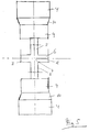
- In Fig. 3 there ist shown the combination of a distance element (2), which is mounted on the carrier profile (1) with a covering element (12). The covering element (12) do fix lower insulation elements (13) and insulation penals (14) after being fastened on the distance elements (2). Possibly the covering elements (12) can be fixed on the distance elements (2) with the help of screws, which are not shown in Fig. 3. The covering elements (12) as well as the carrier profiles (1) are constructed in the form of rails. In an easy to manufacture construction the covering elements (12) have a hat shaped profile.
- The insulation penals (14) can be constructed in the form of cassettes, which do have a covering layer of metal and which are mainly formed of a lightweight insulation material (15).
- On the side of the insulation panels (14) which is arranged opposite to the metallic covering layer (16) there can be arranged a foil (17) to guarantee a sufficient characteristic against water.
- In Fig. 4 there is shown another embodiment of the distance elements (2). This distance element (2) is intended to be installed along a side flange of the insulation panels (14), for example in the middle between two distance elements (2) with cross-shaped plates (6). The distance element according to Fig. 4 has no cross-shaped plate (6) and the dimension of the central plate (7) of this embodiment is dimensioned as the width of the projections (8) of the cross-shaped plate (6). So this distance element (2) can be inserted in the distance between two insulation panels (14).
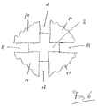
- In the embodiment according to Fi. 6 it can be seen that the cross-shaped plate (6) ist inserted in distances (18) between four insulatin panels (14). With the help of the distance element (2) the position of the insulation panels (14) is defined in the direction from the left to the right as well as in the direction from the lower side to the upper side.
- In Fig. 7 there is shown the construction of the covering element (12) in detail. The covering elements (12) include a base section (19), two side flanges (20) extending from the base section (19), two top sections (21), two end flanges (22) and two contact sections (23), which are intended for a direct contact with a surface of the insulation panels (14). Preferably the above referenced elements of the covering element (12) are formed from a one-piece metal sheet in a bending process. Preferably the angles between at least two of these parts are in the range of 90°.
- In Fig. 8 there is shown a clamp (24), which is intended for covering the ends of two covering elements (12), which are placed beneath each other. Such covering of two neighboured covering elements (12) by a clamp (24) is shown in Fig. 9.
- Fig. 10 do show the crossing area of two covering elements (12). To enable such a crossing the covering elements (12) are constructed with cut outs (25).
- In Fig. 11 there is shown one covering element (12) with a cut out (25).
- Fig. 12 do show two crossing covering elements (12) in another view.
- According to the embodiment in Fig. 13 it is possible, too, to use the distance element (2) for a connection of wall plates (26) and top plates (27), which are intended for the insulation of a load room (28) of a ship. For this embodiment the same carrier profiles (1) can be used and it is only necessary to modify the bendings of the distance elements (2). By this construction preferable the base plate (10) can be orientated with an angle of 45°.
Claims (10)
- Fastening system for ship insulation inside a load room (28) of a ship, which is intended for a defined positioning of insulation panels (14), which are arranged along of carrier profiles (1), characterized in that the system do contain distance elements (2), which are able to be arranged and to be fastened on the carrier profiles (1) and which do extend from the carrier profiles (1) within distances (18) between the insulation panels (14) and which do define the position of the insulation panels (14) only in two dimensions parallel to the plane defined by the carrier profiles (1) and that additional to the distance elements (2) there are used covering elements (12), which are able to be connected with the distance elements (2) and which do define the position of the insulation panels (14) in a third dimension, which do extend vertical to the plane defined by the carrier profiles (1).
- Fastening system according to claim 1, characterized in that the distance elements (2) do extend within the distances (18) between the insulation panels (14) in the region of a cross-point near four corners of four insulation panels (14) with a cross-shaped plate (6).
- Fastening system according to claim 1 or 2, characterized in that two projections (8) of the cross-shaped plate (6) are connected with side flanges (9) in the form of a bend.
- Fastening system according to claims 3, characterized in that the bend do define an angle with a value in the range of 90°.
- Fastening system according to one of the claims 1 to 4, characterized in that the side flanges (9) are connected with base plates (10) in the form of a bend.
- Fastening system according to claim 5, characterized in that the bend do define an angle with the value in the range of 90°.
- Fastening system according to one of the claims 1 to 6, characterized in that the base plates (10) are connected with fastening plates (4) in the form of a bend.
- Fastening system according to claim 7, characterized in that the bend do define an angle with the value in the range of 90°.
- Fastening system according to one of the claims 1 to 8, characterized in that the cross-shaped plate (6), the side flanges (9), the base plates (10) and the fastening plates (4) are formed as a one-piece product.
- Fastening system according to one of the claim 1 to 9, characterized in that in one or more regions of the distance elements (2) there are arranged weight saving holes (11).
Priority Applications (1)
| Application Number | Priority Date | Filing Date | Title |
|---|---|---|---|
| EP95115100A EP0764576A1 (en) | 1995-09-25 | 1995-09-25 | Fastening system for ship insulation |
Applications Claiming Priority (1)
| Application Number | Priority Date | Filing Date | Title |
|---|---|---|---|
| EP95115100A EP0764576A1 (en) | 1995-09-25 | 1995-09-25 | Fastening system for ship insulation |
Publications (1)
| Publication Number | Publication Date |
|---|---|
| EP0764576A1 true EP0764576A1 (en) | 1997-03-26 |
Family
ID=8219651
Family Applications (1)
| Application Number | Title | Priority Date | Filing Date |
|---|---|---|---|
| EP95115100A Withdrawn EP0764576A1 (en) | 1995-09-25 | 1995-09-25 | Fastening system for ship insulation |
Country Status (1)
| Country | Link |
|---|---|
| EP (1) | EP0764576A1 (en) |
Cited By (1)
| Publication number | Priority date | Publication date | Assignee | Title |
|---|---|---|---|---|
| FR2761392A1 (en) * | 1997-04-01 | 1998-10-02 | Quille Entreprise | DEVICE FOR PROVISIONAL REPAIR OF CLADDING |
Citations (2)
| Publication number | Priority date | Publication date | Assignee | Title |
|---|---|---|---|---|
| DE540236C (en) * | 1928-10-09 | 1931-12-09 | Erwin Carstens Dipl Ing Dr | Covering for the insulation of vehicle coolers |
| AT369476B (en) * | 1980-10-24 | 1983-01-10 | Rakenneasennus & Stahlberg | DEVICE FOR FIXING PANELS ON A PAD |
-
1995
- 1995-09-25 EP EP95115100A patent/EP0764576A1/en not_active Withdrawn
Patent Citations (2)
| Publication number | Priority date | Publication date | Assignee | Title |
|---|---|---|---|---|
| DE540236C (en) * | 1928-10-09 | 1931-12-09 | Erwin Carstens Dipl Ing Dr | Covering for the insulation of vehicle coolers |
| AT369476B (en) * | 1980-10-24 | 1983-01-10 | Rakenneasennus & Stahlberg | DEVICE FOR FIXING PANELS ON A PAD |
Cited By (2)
| Publication number | Priority date | Publication date | Assignee | Title |
|---|---|---|---|---|
| FR2761392A1 (en) * | 1997-04-01 | 1998-10-02 | Quille Entreprise | DEVICE FOR PROVISIONAL REPAIR OF CLADDING |
| EP0869234A1 (en) * | 1997-04-01 | 1998-10-07 | SNC Quille Bruyère GCH Patrizio Chrétien Lesage | Method of provisional repair of cladding |
Similar Documents
| Publication | Publication Date | Title |
|---|---|---|
| CA2412726C (en) | Structural member for use in the construction of buildings | |
| US5046294A (en) | Perimeter clip | |
| US3677589A (en) | Field installation clip for exposed grid systems | |
| US4560301A (en) | Heavy slope and skew sheet metal hanger and method of making same | |
| US4364215A (en) | Suspended ceiling assembly and stabilizer bar therefor | |
| US4513551A (en) | Structural support | |
| KR960704130A (en) | LOW PROFILE RAISED PANEL FLOORING WITH METAL SUPPORT STRUCTURE | |
| CN1989306A (en) | Curved ceiling panel | |
| US5644883A (en) | Multiple use corner clip | |
| US5732521A (en) | Longitudinal or transverse support for ceiling panelling | |
| US6672025B1 (en) | Curved building panel with stress-reducing apertures | |
| US4308706A (en) | Support beam for wall or ceiling panels | |
| US6446406B1 (en) | Direct attached grid | |
| EP0764576A1 (en) | Fastening system for ship insulation | |
| US5485706A (en) | Offset forming of structural components | |
| US5117602A (en) | Structural panel for pre-fabricated buildings | |
| GB2099475A (en) | Suspended ceiling bracket | |
| KR200362776Y1 (en) | Combined duct and cable tray | |
| KR100670604B1 (en) | Combined duct and cable tray | |
| GB1558727A (en) | Supsended ceiling | |
| US5244264A (en) | Wrap around base rail assembly for rooftop air conditioners | |
| US5383317A (en) | Shaft wall cavity extension | |
| JPS5839754B2 (en) | Suspension support device for flat cables | |
| US6390420B1 (en) | Electrician's clip and method of using | |
| US11480293B2 (en) | Adjustable overhead mountable storage system |
Legal Events
| Date | Code | Title | Description |
|---|---|---|---|
| PUAI | Public reference made under article 153(3) epc to a published international application that has entered the european phase |
Free format text: ORIGINAL CODE: 0009012 |
|
| AK | Designated contracting states |
Kind code of ref document: A1 Designated state(s): AT BE DE DK ES FR GB GR IT LU NL PT SE |
|
| STAA | Information on the status of an ep patent application or granted ep patent |
Free format text: STATUS: THE APPLICATION IS DEEMED TO BE WITHDRAWN |
|
| 18D | Application deemed to be withdrawn |
Effective date: 19970927 |