EP0764417B1 - Anlage zum Kontrollieren und Erfassen von Anschaffungen in einer Selbstbedienung - Google Patents
Anlage zum Kontrollieren und Erfassen von Anschaffungen in einer Selbstbedienung Download PDFInfo
- Publication number
- EP0764417B1 EP0764417B1 EP96400917A EP96400917A EP0764417B1 EP 0764417 B1 EP0764417 B1 EP 0764417B1 EP 96400917 A EP96400917 A EP 96400917A EP 96400917 A EP96400917 A EP 96400917A EP 0764417 B1 EP0764417 B1 EP 0764417B1
- Authority
- EP
- European Patent Office
- Prior art keywords
- station
- work station
- unloading
- trolley
- assembly according
- Prior art date
- Legal status (The legal status is an assumption and is not a legal conclusion. Google has not performed a legal analysis and makes no representation as to the accuracy of the status listed.)
- Expired - Lifetime
Links
Images


Classifications
-
- A—HUMAN NECESSITIES
- A47—FURNITURE; DOMESTIC ARTICLES OR APPLIANCES; COFFEE MILLS; SPICE MILLS; SUCTION CLEANERS IN GENERAL
- A47F—SPECIAL FURNITURE, FITTINGS, OR ACCESSORIES FOR SHOPS, STOREHOUSES, BARS, RESTAURANTS OR THE LIKE; PAYING COUNTERS
- A47F9/00—Shop, bar, bank or like counters
- A47F9/02—Paying counters
- A47F9/04—Check-out counters, e.g. for self-service stores
-
- G—PHYSICS
- G07—CHECKING-DEVICES
- G07G—REGISTERING THE RECEIPT OF CASH, VALUABLES, OR TOKENS
- G07G1/00—Cash registers
- G07G1/0036—Checkout procedures
Definitions
- the present invention relates to an assembly intended for control and recording of purchases made by a consumer in a self-service point of sale, and in particular using a container and / or trolley.
- the control and recording stations used for this day have a treadmill on which the consumer unloads the goods contained in the carriage.
- the cashier (hereinafter the operator) takes the items one by one to save them using a cash register which stores the price and the name of the article, mentioned by a code arranged on the item, called barcode.
- the operator enters barcode information either manually or automatically using a laser reading device (to scan). The operation is thus continued until registration of all selected goods by the consumer, who then makes the payment for the total sum of the goods purchased. Payment is done on the same computer as the registration, and by through the same operator. Concomitantly, and more generally after the payment transaction, the consumer must recharge his cart to dispose of it either the articles themselves, or the latter arranged in plastic bags that the operator will have him provides as you register.
- Unloading, registration, payment and the truck is loaded at the same station, and by the same operator. These operations must be done almost sequentially, and it results in an increase in the time required for each consumer to perform all of these operations; the consumer is therefore obliged to park a time relatively long at the checkout to perform these operations. Also, the unloading operations, registration and payment made by one person increase the complexity of the tasks at hand by a single operator.
- the management of self-service stores must take into account the indelicacies, not only of customers, but also of staff, and more known as the "convenience truck", which consists, for an operator of checkout, to record items and / or prices that have no relation to those actually present in the cart and carried away by the consumer, colluding with the operator.
- the current system does not effectively combat these actions.
- the present invention aims to remedy these drawbacks and proposes a method and means of implementation, allowing a consumer register purchased items, pay the price, and leave the store after a reduced wait at minimum.
- the method and the device of the invention aims also to optimize the management of personnel at the level of free shop exit controls service, both qualitatively and quantitatively, while improving safety and reducing risk of "carriage of convenience".
- the assembly for the control and recording of purchases made by a consumer in a self-service point of sale such as comprising an unloading station for said purchases, from a cart and / or container, a workstation provided with means of recording and accounting entry of said purchases, and capable of being occupied by a person, further includes a loading station, said stations respective unloading and loading being placed substantially opposite each other and on each side said workstation, the unloading station comprising a first tray of unloading within the person's grasp occupying said work station, characterized in that the work station work is rotatably mounted on a vertical axis, view of turning the operational side either upstream, either downstream, allowing said workstation to be used interchangeably either by the consumer (in the upstream position), either by a operator of the point of sale (in the turned position downstream).
- the loading station includes a location suitable for receiving a trolley.
- said first tray being of a shape and dimension suitable for allowing the support and the stable maintenance of containers.
- the first tray includes a part whose surface corresponds substantially to a container and is tilted, at least in a direction, towards said work station, a at least stop being provided for the container corresponding.
- said unloading station includes a second plate, arranged on the side opposite to said first tray with respect to said work station, and comprising conveying members, such as rollers.
- the set includes immobilization means temporary carriage in said location, such as a electro magnet.
- said work station includes a operator's seat, slidably mounted between an active position for use by a operator, and a retracted position for consumer use.
- the loading station comprises a tray, preferably retractable, for supporting the less temporary of a container, before its installation on the cart placed in the location of the loading.
- the invention also relates to a unit for monitoring and recording purchases made by a consumer in a self-service point of sale, characterized in that it includes at least two sets such that described, and preferably three or four sets arranged side by side, around a central point and angularly offset according to a general form of either Y, either V, or chevron.
- the unit also comprises at least one separate payment station located at a distance from said or of said set (s).
- the invention also relates to a point of sale of the type self-service with at least two units such as described.
- passages are planned for the consumer, and the width of about 90cm to allow passage cars for the disabled.
- passages are provided between the post of payment 7 and barriers 4 and 5, respectively 9 and 10 through which the consumers leave the store towards the outlet, this displacement being symbolized by the arrows i, j.
- passages are provided 11 and 12 respectively for customers and their cart, according to a direction of advancement symbolized by arrows k and 1, parallel to arrows i and j.
- the unit 13 comprises three unloading assemblies, recording, checking and loading, arranged contiguously, and bearing the general references A, B and C.
- Each set is made up of different elements bearing indices A, B and C, associated with references of each of the elements. So the set A includes an unloading station 14A, a work for the control and recording of goods, referenced 15A, and a loading station 16A.
- the sets B and C likewise include a unloading respectively 14B and 14C, a work 15B and 15C, and a loading station 16B and 16C.
- FIGS. 2A and 2B show views in plunging perspective, from different angles, of unit 13, composed of three sets A, B and C, of the figure 1.
- FIGS. 2A and 2B bearing the same references, and in particular the unloading 14A, 14B and 14C, work stations 15A, 15B and 15C, the loading stations 16A, 16B and 16C.
- the sets are arranged relative to each other, to form unit 13, around a central point symbolized by the orientation and marking mast 17.
- the together A, B and C are thus arranged so angularly offset to form a kind of Y whose center is represented by mast 17.
- Each workstation 15A, 15B and 15C has a operator seat. Only seats 18A and 18C are represented.
- Figures 3A and 3B show in perspective a work, for example, post 15B.
- This includes a base or platform 20, generally parallelepipedic in shape and elongated, and on which is rotatably mounted as explained later, a base 21 at the top of which a shelf 22 and a console 23 are provided. last is associated and includes means of registration and control known in themselves and including a fixed barcode reader and a reader mobile 24, of the scanner type.
- the corresponding seat which has not been shown for clarity, is fixed on the platform 20.
- a footrest 25 is provided on the base for operator comfort.
- the scanner stationary and the mobile scanner 24 translate the barcode displayed on articles, in information relating to cost of the item and its identification, this information being memorized and displayed as and as is known in the console 23.
- the means of recording and control are associated with calculation and printing means.
- the unloading station 14A has a main plate 27A, arranged near the substation work 15A, and an auxiliary plate 26A contiguous to main plate 27a, on the opposite side of the latter by report to workstation 15A.
- the auxiliary tray 26A includes routing means, such as rollers, or a treadmill, so that move, effortlessly, or with minimal effort, containers to be placed on the shelf auxiliary 26A, to the main plate 27A.
- the post of work 15A, 15B and 15C each set is arranged between the unloading station and the loading station, these three posts being appreciably of general management parallel to the general direction of advancement and movement of the consumer, as mentioned above, and corresponding to the respective arrows f, g, h.
- Each unloading station consists of a corresponding shape and dimension location substantially like a self-service type cart.
- the location corresponding to the 16C loading station said location being delimited by the edges of the platform 20C, of the work station 15C, and a credenza 28, in the form of a piece of furniture parallelepiped, arranged between the two loading 16B and 16C.
- the credenza 28 thus comprises two walls 29 and 29 'vertical, parallel to the direction progress.
- the wall 29 of the credenza 28 and the edge of the platform 20C thus conforming a sort of L in view of above, corresponding to the loading station 16C, suitable for receive a cart.
- a guide rail 30C is provided on along the edge of the platform 20C.
- the wall 29 of the credenza 28 is provided with immobilization means at its base temporary carriage, marked 31.
- These immobilization means are preferably constituted an electrical circuit comprising an electromagnet 32 able to cooperate with a corresponding fixed plate on the cart. So when the carriage comes up against against the means 31, the metal plate placed on the carriage comes into contact with the electromagnet 32, this which immobilizes the trolley.
- This immobilization temporary is not compulsory, but allows on the one hand avoid any untimely movement of the trolley when loading, and secondly to block the carriage for avoid any questionable or indelicate action of a consumer.
- the control of the electromagnet is performed automatically through a contactor located in the center of the electromagnet support 32.
- the contactor as soon as the truck plate abuts the electromagnet, causes feeding the latter, and therefore immobilizing the carriage.
- the carriage is released the unloading station (for example 16A) by cutting the electromagnet supply.
- the cut feeding of the latter is carried out automatically by transmission by means of recording and counting, at the workstation, of the total amount representing the goods placed in the cart and counted, and issuing a ticket correspondent for the customer / consumer.
- it is possible to provide for the maintenance and / or the release of the carriage manually, by intervention either by the operator at the workstation, either from the operator at the downstream payment station. Keeping the cart at the loading station presents also the advantage of limiting travel untimely of the latter during loading, for the customer convenience.
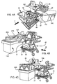
- FIGS. 4A to 4G show only part of the whole corresponding, in use, and from angles different to facilitate understanding.
- a carriage 33 is disposed near and against a station corresponding 14C discharge, consisting of a tray 34C, on which are able to be placed the goods either in bulk or placed in containers.
- Containers are preferably parallelepiped with an upper opening. So, on the tray 34C are shown two containers 35 and 36, while the carriage 33 comprises on its plate upper 37 two containers 38 and 39.
- the layout of the trolley 33, the unloading tray 34C and the 15C work, is such that these have a general orientation parallel to each other, and also parallel to the general advancement branch of the consumer (arrow f).
- the consumer unloads his cart 33 by arranging the containers 35, 36, 38, 39, on the unloading tray 34C.
- This one has a shape and dimensions such that it can support four containers, in the example represented.
- FIG. 4B the assembly A against which is arranged a carriage 40, the upper plate 41 contains two series of four stacked containers, and of which the lower plate 42 comprises goods bulky, represented by block 43.
- the carriage 40 is arranged opposite the unloading means 14A.
- the consumer then moves the containers placed on the trolley, on the unloading station.
- a cart comprising eight containers arranged in two layers of four stacked containers and stacked two by two in height. At first, the consumer unloads the four containers of the part to place them on the auxiliary station of unloading 26A. Secondly, the consumer then unload the remaining four containers arranged on the cart to place them on the main tray 27A unloading. The cart is then empty and it is moved to the loading station.
- the main tray 27A is released and it is then possible for the operator to move full containers from the tray auxiliary 26A, to the main plate 27A, and this by means of routing (rollers, conveyor belt or similar), presenting a direction of work directed to the corresponding workstation.
- FIG. 4C the assembly of FIG. 4B, at a later stage where the carriage 40 is partially unloaded, from several containers placed on the first auxiliary unloading tray 26A.
- An operator 45 is represented at workstation 15A.
- Figures 4D and 4F refer to set C
- Figures 4E and 4G refer to assembly A.
- the carriage A1 arranged at near the unloading station 14A, once completely discharged, is moved by the consumer to loading station 16A, where the trolley is represented by the reference A2.
- the curved arrow m symbolizes the passage of the carriage from its position A1 towards its position A2.
- Figures 4E and 4G show the corresponding A2 trolley, in place in the loading. In this position, the carriage is susceptible to be immobilized by means 31 and the electromagnet 32 ( Figure 2C).
- Figure 4G shows the carriage in place, being however offset compared to the means immobilizer 31, for reasons of clarity.
- a metal plate 46 capable of cooperating with the electromagnet 31.
- Figures 4D and 4F show a trolley at the loading station at station 15C.
- an arch protection 47 is provided at the corner of the workstations 15A and 15C correspondents to protect the work when moving the carriage from position A1 (unloading station) to position A2 ( loading).
- operator 45 at his workstation 15A (or 15C), is therefore facing console 23 (figure 3A), and to its right (or its left) is the tray unloading 14A or (14C), on which rest full containers, and to its left (or right) is finds the carriage A2 in the standby position.
- the first one operation performed by operator 45, with reference to the Figure 4E, is to record and account for objects bulky possibly arranged on the tray lower 42 of the carriage. The consumer does not have to unload these bulky items that he can leave on the lower shelf, which has a great advantage over the ceremoniity plan.
- the operator enters information relating to bulky goods 43, to using the mobile scanner 24, in the usual manner.
- the operator can then start recording and accounting items placed in containers waiting in the unloading station 14A. Beforehand, the client will have placed on the waiting cart, an empty container in his possession, unless, in his absence, the operator will have a container taken from the stock at its arrangement in an ad hoc piece of furniture.
- the containers are of the parallelepiped type, preferably plastic, but which can be also in cardboard or paper, and foldable so that have a substantially planar shape, and therefore a reduced size once folded.
- Containers a once folded are arranged in ad hoc furniture, to proximity to work stations.
- the folded containers are stored in the credenza 28 accessible from either of these posts.
- the containers folded are stored in the cabinet 51 ( Figure 4E). The customers can use their own containers.
- the operator 45 at the start of the recording operations, has an empty container on the left (or right) placed on the trolley (placed at the loading station), and to his right (or to his left) of a set of containers full waiting and arranged on the tray unloading 27 (27A for example).
- the operator enters the items one by one from a first container, saves them or counts using the scanner, then replaces them in the container on the cart, until empty the first container placed on the tray unloading, and fill the first container disposed at the origin on the cart.
- the operator then enters the container that has just been emptied, from the tray unloading, to place it on the cart.
- the recording and control operations continue in the same way by emptying each container arranged waiting on the unloading tray, and filling corresponding containers placed on the trolley, placed him in the loading station.
- the operator therefore places the articles in front of him (dotted arrow n in Figure 1) and preferably on the work table 22 (FIG. 3A), provided with a fixed scanner.
- the mobile scanner 24 ( Figures 3A and 3B) is used for bulky items or labels difficult to access.
- the loading station 16A includes a sliding plate 50, and the surface of which corresponds substantially on the bottom surface of a container, so that a container can rest on the tray mobile 50. It is likely to slide between an active position ( Figure 4G) supporting a container and a retracted or inactive position, where it is placed on top of the credenza 51.
- the tray mobile 50 can be slidably mounted, by one of its ends, on a vertical wall of the cabinet 51, the tray being retained by two lateral connecting rods. The plate 50 is thus movable between an active position perpendicular to the vertical wall of the cabinet 51 and a vertical folded position, against said partition.
- the movable plate 50 serves as a support temporary to the container being filled, this in the case where the upper plate of the carriage A2 is already loaded with a first series of containers, and that a second series of containers must be placed on the first series. The second series in the upper part is therefore elevated. The upper opening of containers would therefore be at a height which would make it inconvenient or even difficult, filling these containers by the operator who should then lift the articles.
- the movable plate 50 makes it possible to place temporarily the container being filled to a convenient height.
- the latter In order to facilitate and make even easier the emptying of each container, placed on the unloading tray, the latter is provided, with reference to FIGS. 5 and 6, of an inclined part and bearing the reference 53. This the latter is tilted towards the operator, so that the opening of the corresponding container bearing the reference 54 ( Figure 5) or slightly tilted towards the operator, which increases accessibility inward of the container. Edge 55 of the tray corresponding unloading, forms a stop.
- a plate or guardrail 56 is planned in order to maintain the containers and avoid any untimely tipping. Guardrail or full plate 56 also plays another role, namely that of support for heavy objects removed from the container by the operator, at the workstation, to arrange them in a container placed on the trolley at the loading.
- the operator to manipulate the heavy objects, such as bottles for example, lifts them from the container by leaning on them the bottle on the railing, then slide it on said railing, thereby relieving the operator's work when picking up items of the container being posted, and arranged on the main plate 27A of the unloading station 14A.
- Figures 3A and 3B show a workstation with a base 21 / shelf 22 / console 23, rotatably mounted on a vertical axis with respect to the platform 20.
- the console 23 is movable horizontally to adapt to the operator.
- control and accounting system articles means enabling the consumer / client perform the accounting itself and the registration of the articles he has selected for of their purchase, and arranged on his cart.
- the method of accounting and recording is much the same as described above, with reference to operations performed by a operator.
- the only difference is that the client himself stands upright in the workstation, facing the console, and account for items by doing them pass in front of the stationary scanner, and / or use the scanner mobile to store large objects arranged on the lower shelf of the cart, or objects whose the barcode is difficult to access.
- the work station and in particular the active part, i.e. the base / console assembly / tablet is movable between two positions 180 ° apart from each other.
- the entire workstation is shown facing the operator (on the seat side 18).
- the workstation 15A for three different positions from the base 21, work table 22 and console 23.
- the seat 18A associated with the console is shown also.
- the first position of the workstation shown on the Figure 7a corresponds to the use of the latter by a operator. This one sits on seat 18A and does facing the console 23. This position is referenced below “downstream position", referring to the direction general advancement of the consumer and represented by the arrow f similar to that shown in FIG. 1.
- This configuration has an important advantage since it allows the consumer to carry out himself registration of goods in case of crowds unexpected.
- the seat 18A is capable of sliding relative to the platform 20, by any known means.
- FIG. 8 a detailed view of the foot 60 of the seat 18, comprising three branches 61, 62 and 63, offset angularly on a regular basis, to ensure a base stable at headquarters.
- One of the legs 63 of legs is integral with a slide 64, itself capable of cooperate with a slide 65 fixed to the platform 20.
- the consumer then moves his cart filled to one of the payment stations, and closest preference. So, with reference to the FIG. 1, the consumer coming from set A, moves his cart from position A2 to position A3 then A4, to payment station 8. In terms of set C, the consumer moves his cart from the position C2 to position C3. For set B, the consumer moves his cart from position B2 to position B3. Finally, for one of the sets, referenced D, from neighboring unit 13 ', the consumer moves his carriage from position D2 to position D3.
- FIG. 9 shows a plan view, similar to that of FIG. 1, of a variant of realization comprising units, each comprising two sets of the invention, arranged to form a V.
- the units of the embodiment shown in Figure 1 have three sets arranged to form a Y.
- the sets arranged in V of each unit shown in figure 9, form an open V on the outlet side of the store, the point being directed towards the rays or linear.
- Figure 10 shows a perspective view schematic of a unit comprising two sets arranged in V. Elements and means similar to those Figures 1 to 8 have the same references.
- each set includes a simple unloading station, i.e. similar to sets B and C of figure 1, unlike assembly A whose unloading station 14A comprises two trays, for reasons for example congestion.
- Each payment item consists of a piece of furniture general cubic shape and closed by partitions for delimit an interior space in which a seat 66.
- the furniture constituting the payment station has a flat part, in the form of a tray 67 assigned operations relating to a given customer and a given cart, arranged on either side of the work (see Figure 1).
- One of the sides of the cabinet 8 can be closed off temporarily through a door 70.
- Panels in rigid transparent material 71, 72 and 73, are arranged on the sides and behind the interior location of the cabinet 8, in the upper part to isolate the operator.
- the operator of the payment station has various means, known in themselves and which are not described in more detail, allowing you to collect and save the payment by the consumer of the goods he has bought and placed on his cart, and who come to be saved using the sets previously described.
- These means include among others payment card recorders 68 and 69.
- the payment stations are provided with means of distribution and routing of the type pneumatic 74, to allow operators to each payment item to route, under conditions optimal security, funds, checks, or any other important and precious document, from their post of payment to the central cashier or any place determined from the store.
- the payment item is also used to control recording operations. Indeed, the operator of the payment station can fully monitor and control the execution of operations taking place each unit and each set of recording and item accounting, especially in the cases where these operations are carried out by the consumer himself.
Landscapes
- Physics & Mathematics (AREA)
- General Physics & Mathematics (AREA)
- Warehouses Or Storage Devices (AREA)
- Cash Registers Or Receiving Machines (AREA)
Claims (15)
- Aufbau zur Kontrolle und Registrierung von Einkäufen, die von einem Verbraucher in einer Selbstbedienungseinrichtung getätigt werden, des Typs, der folgendes aufweist: eine Ausladestelle (14A, 14B, 14C) für die Einkäufe aus einem Wagen (33) und/oder einem Behälter (35, 36, 38, 39), eine Abfertigungsstelle (15A, 15B, 15C), die mit Registrier- und Buchungserfassungsmitteln für die Einkäufe ausgerüstet und zur Besetzung durch eine Person geeignet ist, eine Einladestelle (16A, 16B, 16C), die zur Aufnahme eines Wagens (33) in der Lage ist. wobei die entsprechenden Auslade- (14A, 14B, 14C) und Einladestellen (16A, 16B, 16C) im wesentlichen einander gegenüber und auf jeder Seite der Abfertigungsstelle (15A, 15B, 15C) angeordnet sind, wobei die Ausladestelle (14A, 14B, 14C) eine Auslade-Hauptplattform (27A) in Reichweite der Person, die die Abfertigungsstelle (15A, 15B, 15C) besetzt, aufweist, dadurch gekennzeichnet, daß die Abfertigungsstelle (15A, 15B, 15C) um eine vertikale Achse drehbar montiert ist, wodurch sich die Abfertigungsstelle (15A, 15B, 15C) beliebig, entweder von dem Verbraucher oder von einer Betriebsperson (45) der Verkaufseinrichtung, einsetzen läßt.
- Aufbau nach dem vorhergehenden Anspruch, dadurch gekennzeichnet, daß die Abfertigungsstelle (15A, 15B, 15C) einen Sitz (18A, 18B, 18C) aufweist, der zwischen einer funktionsfähigen Position zur Verwendung durch eine Betriebsperson (45) und einer eingeklappten Position zur Verwendung durch den Verbraucher gleitend montiert ist.
- Aufbau nach einem der vorhergehenden Ansprüche, dadurch gekennzeichnet, daß die Einladestelle (16A, 16B, 16C) einen abgegrenzten Platz aufweist, der zur Aufnahme eines Wagens (33) zu seiner Führung und zu seiner temporären Immobilisierung geeignet ist.
- Aufbau nach einem der vorhergehenden Ansprüche, dadurch gekennzeichnet, daß der Platz der Einladestelle (16A, 16B, 16C) durch die Ränder einer Bühne (20) der Abfertigungsstelle (15A, 15B, 15C) und ein Seitentischchen (28). die in der Draufsicht ein L bilden, das zur Aufnahme des Wagens (33) geeignet ist, abgegrenzt ist.
- Aufbau nach einem der vorhergehenden Ansprüche, dadurch gekennzeichnet, daß die Hauptplattform (27A) einen Teil aufweist, dessen Oberfläche im wesentlichen einem Behälter entspricht und, mindestens in eine Richtung, gegen die Abfertigungsstelle (15A, 15B, 15C) geneigt ist, wobei mindestens ein Anschlag für den entsprechenden Behälter vorgesehen ist.
- Aufbau nach einem der vorhergehenden Ansprüche, dadurch gekennzeichnet, daß er an dem Platz temporäre Immobilisierungseinrichtungen für den Wagen aufweist, die in Form eines Elektromagneten (32) vorliegen, der einem Kontaktstück beigefügt ist. das zur Auslösung der Stromspeisung des Elektromagneten (32) beim Anstoßen des Wagens (33) an den Elektromagneten (32) geeignet ist.
- Aufbau nach Anspruch 6, dadurch gekennzeichnet, daß der Wagen (33) durch Unterbrechen der Speisung des Elektromagneten (32) von der Ausladestelle (14A, 14B, 14C) gelöst wird, wobei das Unterbrechen automatisch durch Ausgabe der Gesamtsumme und des entsprechenden Kassenzettels durch die Abfertigungsstelle (15A, 15B, 15C) oder per Hand durch Eingreifen einer Betriebsperson (45) durchgeführt wird.
- Aufbau nach einem der vorhergehenden Ansprüche, dadurch gekennzeichnet, daß die Ausladestelle (14A, 14B, 14C) eine Hilfsplattform (26A) aufweist, die bezüglich der Abfertigungsstelle (15A, 15B, 15C) auf der gegenüberliegenden Seite der Hauptplattform (27A) angeordnet ist und Transportorgane, wie Walzen oder ein Laufband, mit einer zu der entsprechenden Abfertigungsstelle (15A, 15B, 15C) führenden Arbeitsrichtung aufweist.
- Aufbau nach einem der vorhergehenden Ansprüche, dadurch gekennzeichnet. daß die Abfertigungsstelle (15A. 15B. 15C) eine Konsole (23) aufweist, die den Registrier- und Erfassungsmitteln beigefügt und auf einem Gestell (21) so befestigt ist, daß sie. wenn sie stromaufwärts gedreht wird, der allgemeinen Vorschubrichtung des Verbrauchers folgt und so für letzteren die direkte Verwendung der Abfertigungsstelle (15A, 15B, 15C) möglich ist.
- Aufbau nach einem der vorhergehenden Ansprüche, dadurch gekennzeichnet, daß die Einladestelle (16A, 16B, 16C) eine vorzugsweise einziehbare Plattform (50) zur mindestens zeitweisen Stütze eines Behälters während des Befüllens vor seiner Überführung auf den Wagen, der zur Aufnahme an dem Platz bestimmt ist. aufweist.
- Aufbau nach einem der vorhergehenden Ansprüche, dadurch gekennzeichnet, daß die Abfertigungsstelle (15A, 15B, 15C) ein mobiles Lesegerät (24) aufweist, durch das sich Informationen über schwere Artikel, die auf einer unteren Plattform (42) des Wagens (40) angeordnet sind, erfassen lassen.
- Einheit zur Kontrolle und Registrierung von Einkäufen, die von einem Verbraucher in einer Selbstbedienungseinrichtung getätigt werden, dadurch gekennzeichnet, daß sie mindestens zwei Aufbauten nach einem der vorhergehenden Ansprüche aufweist.
- Einheit nach Anspruch 12, dadurch gekennzeichnet, daß sie drei Aufbauten aufweist, die Seite an Seite um einen Mittelpunkt angeordnet und in der Grundform eines Y winklig zueinander verschoben sind.
- Einheit nach einem der Ansprüche 12 oder 13, dadurch gekennzeichnet, daß sie ferner mindestens eine von dem oder den Aufbau(ten) verschiedene und beabstandete Zahlstelle (7, 8) aufweist.
- Verkaufsstelle vom Selbstbedienungstyp, die mit mindestens zwei Einheiten nach einem der Ansprüche 12 bis 14, wobei jede Einheit mindestens zwei Aufbauten aufweist, und mit mindestens einer Zahlstelle (7, 8), die seitlich und bezüglich der zwei Einheiten stromabwärts verschoben ist, ausgestattet ist.
Applications Claiming Priority (2)
| Application Number | Priority Date | Filing Date | Title |
|---|---|---|---|
| FR9511021 | 1995-09-20 | ||
| FR9511021A FR2738734B1 (fr) | 1995-09-20 | 1995-09-20 | Ensemble pour le controle et l'enregistrement d'achats dans un lieu de vente a libre service |
Publications (2)
| Publication Number | Publication Date |
|---|---|
| EP0764417A1 EP0764417A1 (de) | 1997-03-26 |
| EP0764417B1 true EP0764417B1 (de) | 2002-07-17 |
Family
ID=9482742
Family Applications (1)
| Application Number | Title | Priority Date | Filing Date |
|---|---|---|---|
| EP96400917A Expired - Lifetime EP0764417B1 (de) | 1995-09-20 | 1996-04-29 | Anlage zum Kontrollieren und Erfassen von Anschaffungen in einer Selbstbedienung |
Country Status (6)
| Country | Link |
|---|---|
| US (1) | US5884728A (de) |
| EP (1) | EP0764417B1 (de) |
| ES (1) | ES2180713T3 (de) |
| FR (1) | FR2738734B1 (de) |
| PL (1) | PL315925A1 (de) |
| PT (1) | PT764417E (de) |
Families Citing this family (24)
| Publication number | Priority date | Publication date | Assignee | Title |
|---|---|---|---|---|
| US6332575B1 (en) | 1997-10-31 | 2001-12-25 | Symbol Technologies, Inc. | Audible indicators for optical code reading systems |
| US6330973B1 (en) | 1989-10-30 | 2001-12-18 | Symbol Technologies, Inc. | Integrated code reading systems including tunnel scanners |
| US5967264A (en) | 1998-05-01 | 1999-10-19 | Ncr Corporation | Method of monitoring item shuffling in a post-scan area of a self-service checkout terminal |
| CN100395768C (zh) * | 1998-10-30 | 2008-06-18 | 讯宝科技公司 | 改进的包括隧道扫描器的集成的代码阅读系统 |
| AU2003221370B2 (en) * | 1998-10-30 | 2004-08-26 | Symbol Technologies, Inc. | Improved Integrated Code Reading Systems Including Tunnel Scanners |
| US6286758B1 (en) * | 1999-02-17 | 2001-09-11 | Ncr Corporation | Reconfigurable checkout system |
| US6390363B1 (en) | 1999-11-02 | 2002-05-21 | Ncr Corporation | Apparatus and method for operating convertible checkout system which has a customer side and a personnel side |
| US6296184B1 (en) | 1999-11-02 | 2001-10-02 | Ncr Corporation | Apparatus and method for operating a checkout system having a security scale for providing security during an assisted checkout transaction |
| US6502749B1 (en) | 1999-11-02 | 2003-01-07 | Ncr Corporation | Apparatus and method for operating a checkout system having an RF transmitter for communicating to a number of wireless personal pagers |
| US6213395B1 (en) | 1999-11-02 | 2001-04-10 | Ncr Corporation | Apparatus and method for operating a checkout system having a scanner which is rotatable between an assisted scanner position and a self-service scanner position |
| US6530520B1 (en) | 1999-11-02 | 2003-03-11 | Ncr Corporation | Apparatus and method for operating a checkout system having an RF transmitter for communicating to a receiver associated with an intercom system |
| US6427915B1 (en) | 1999-11-02 | 2002-08-06 | Ncr Corporation | Method of operating checkout system having modular construction |
| US6409081B1 (en) * | 1999-11-02 | 2002-06-25 | Ncr Corporation | Apparatus and method for operating a checkout system having an item set-aside shelf which is movable between a number of shelf positions |
| US6354497B1 (en) | 1999-11-02 | 2002-03-12 | Ncr Corporation | Apparatus and method for operating a checkout system having a number of interface terminals associated therewith |
| US6343739B1 (en) | 1999-11-02 | 2002-02-05 | Ncr Corporation | Apparatus and method for operating a checkout system having a video camera for enhancing security during operation thereof |
| US6540137B1 (en) | 1999-11-02 | 2003-04-01 | Ncr Corporation | Apparatus and method for operating a checkout system which has a number of payment devices for tendering payment during an assisted checkout transaction |
| US6296185B1 (en) | 1999-11-02 | 2001-10-02 | Ncr Corporation | Apparatus and method for operating a checkout system having a display monitor which displays both transaction information and customer-specific messages during a checkout transaction |
| US6427914B1 (en) | 1999-11-02 | 2002-08-06 | Ncr Corporation | Apparatus and method for operating a checkout system having a number of port expander devices associated therewith |
| US6588549B2 (en) | 2001-07-06 | 2003-07-08 | Ncr Corporation | Checkout system convertible between assisted and non-assisted configurations |
| AUPR801801A0 (en) * | 2001-09-28 | 2001-10-25 | Douglas, Craig Raymond | Seat reservation system and method |
| US6619546B1 (en) * | 2002-03-14 | 2003-09-16 | Wal-Mart Stores, Inc. | Systems and methods for pre-scanning merchandise in customer's shopping cart while customer is waiting in checkout line |
| US7621446B2 (en) * | 2006-04-11 | 2009-11-24 | International Business Machines Corporation | Convertible self-checkout system |
| NO335097B1 (no) * | 2012-10-31 | 2014-09-15 | Peoplepos Ltd | Fremgangsmåte og anordning for betaling av varer |
| CN105049662A (zh) * | 2015-07-14 | 2015-11-11 | 王彤 | 补充照明的折叠拍摄仪 |
Family Cites Families (13)
| Publication number | Priority date | Publication date | Assignee | Title |
|---|---|---|---|---|
| NL250229A (de) * | 1959-04-06 | |||
| FR1357750A (fr) * | 1963-02-27 | 1964-04-10 | Laitiere Moderne Soc | Perfectionnements aux meubles support pour caisses enregistreuses notamment pour magasins à libre service et analogues |
| GB973444A (en) * | 1964-08-21 | 1964-10-28 | Opus Ltd | Improvements in or relating to self-service store fitting |
| US3270837A (en) * | 1964-09-09 | 1966-09-06 | American Metal Prod | Automatic grocery cart |
| US3557907A (en) * | 1969-06-09 | 1971-01-26 | United Steel & Wire Co | Checkout counter with pivoted cash register |
| US3990540A (en) * | 1975-09-04 | 1976-11-09 | Ncr Corporation | Checkout system |
| US4792018A (en) * | 1984-07-09 | 1988-12-20 | Checkrobot Inc. | System for security processing of retailed articles |
| US5149947A (en) * | 1989-03-27 | 1992-09-22 | Ncr Corporation | Portable checkout system |
| US4953664A (en) * | 1989-05-04 | 1990-09-04 | Sonoco Products Company | Ergonomically designed check-out counter system for supermarket and merchandising industries |
| DE59100967D1 (de) * | 1990-03-30 | 1994-03-17 | Wanzl Metallwarenfabrik Kg | Verfahren zum Einkaufen von Ware in Selbstbedienungsgeschäften. |
| US5211263A (en) * | 1992-01-21 | 1993-05-18 | In-Store Products Limited | Store check-out station |
| FR2711901A1 (fr) * | 1993-11-03 | 1995-05-12 | 3S Payment | Meuble de caisse pour magasins, en particulier à grande surface. |
| JP3102982B2 (ja) * | 1994-01-21 | 2000-10-23 | 東芝テック株式会社 | スキャン切替方式のチェックアウト装置 |
-
1995
- 1995-09-20 FR FR9511021A patent/FR2738734B1/fr not_active Expired - Fee Related
-
1996
- 1996-04-29 ES ES96400917T patent/ES2180713T3/es not_active Expired - Lifetime
- 1996-04-29 PT PT96400917T patent/PT764417E/pt unknown
- 1996-04-29 EP EP96400917A patent/EP0764417B1/de not_active Expired - Lifetime
- 1996-09-04 PL PL96315925A patent/PL315925A1/xx unknown
- 1996-09-19 US US08/716,035 patent/US5884728A/en not_active Expired - Fee Related
Also Published As
| Publication number | Publication date |
|---|---|
| ES2180713T3 (es) | 2003-02-16 |
| FR2738734B1 (fr) | 1997-10-17 |
| EP0764417A1 (de) | 1997-03-26 |
| US5884728A (en) | 1999-03-23 |
| PT764417E (pt) | 2002-11-29 |
| PL315925A1 (en) | 1997-04-01 |
| FR2738734A1 (fr) | 1997-03-21 |
Similar Documents
| Publication | Publication Date | Title |
|---|---|---|
| EP0764417B1 (de) | Anlage zum Kontrollieren und Erfassen von Anschaffungen in einer Selbstbedienung | |
| CA2470457A1 (fr) | Procede et installation automatisee de stockage et de distribution d'objets ou articles divers | |
| EP3947104B1 (de) | Wagen zum tragen und wiegen eines containers | |
| FR3038308A1 (fr) | Dispositif de stockage et de transfert | |
| EP1608470A1 (de) | Behältertransferanordnung für briefsortiermaschine | |
| EP2796390B1 (de) | Automatisches transport- und lagersystem für produkte zur vorbereitung ihrer bestellungen und kontrollverfahren dieses systems | |
| FR2687818A1 (fr) | Poste de controle de sortie de magasin tel que supermarche et similaire. | |
| EP0494014A1 (de) | Erzeugung einer Liste von Gegenständen für die Beladung von Behältern | |
| FR2641887A1 (fr) | Distributeur automatique de bouteilles de gaz liquefie a section circulaire | |
| FR2612884A1 (fr) | Dispositif pour la mise automatique en sacs d'articles debites a la sortie d'un poste de controle | |
| EP2213208B1 (de) | Bifunktionelles System für die Warenerfassung und -bezahlung | |
| US20050183402A1 (en) | Grocery bagging and transfer apparatus | |
| FR2880605A1 (fr) | Dispositif pour transporter confortablement, decharger, recharger automatiquement et enregistrer les articles des produits vendus en libre service | |
| EP0184527A1 (de) | Einrichtung zur automatischen Lagerung, Verteilung und Wiedereinsetzung von Kassetten, Büchern oder ähnlichen Artikeln | |
| EP0277880B1 (de) | Beförderungsvorrichtung, insbesondere für Selbstbedienungsläden | |
| EP1094973B1 (de) | Handhabungssystem für artikel im einzelhandel des kaufhauses | |
| EP0847718B1 (de) | Abrechnungskassenmöbelanordnung für Selbstbedienungsgeschäfte | |
| FR2662591A1 (fr) | Dispositif de distribution automatique d'articles de differentes categories. | |
| FR2672714A1 (fr) | Distributeur automatique d'articles conditionnes. | |
| EP0698260A1 (de) | Automatisches ausgabelager | |
| FR2732876A1 (fr) | Meuble de caisse de magasin | |
| FR2711901A1 (fr) | Meuble de caisse pour magasins, en particulier à grande surface. | |
| EP4049948A1 (de) | Förderwagen mit geneigten stützen und anschlägen | |
| EP0239447A1 (de) | Fakturierungseinrichtung für lose Waren | |
| FR3075440A1 (fr) | Borne de distribution d'echantillons de produits cosmetiques et/ou de parfum |
Legal Events
| Date | Code | Title | Description |
|---|---|---|---|
| PUAI | Public reference made under article 153(3) epc to a published international application that has entered the european phase |
Free format text: ORIGINAL CODE: 0009012 |
|
| AK | Designated contracting states |
Kind code of ref document: A1 Designated state(s): ES GB IT LU PT |
|
| 17P | Request for examination filed |
Effective date: 19970318 |
|
| 17Q | First examination report despatched |
Effective date: 20000712 |
|
| GRAG | Despatch of communication of intention to grant |
Free format text: ORIGINAL CODE: EPIDOS AGRA |
|
| GRAG | Despatch of communication of intention to grant |
Free format text: ORIGINAL CODE: EPIDOS AGRA |
|
| GRAH | Despatch of communication of intention to grant a patent |
Free format text: ORIGINAL CODE: EPIDOS IGRA |
|
| GRAH | Despatch of communication of intention to grant a patent |
Free format text: ORIGINAL CODE: EPIDOS IGRA |
|
| GRAA | (expected) grant |
Free format text: ORIGINAL CODE: 0009210 |
|
| AK | Designated contracting states |
Kind code of ref document: B1 Designated state(s): ES GB IT LU PT |
|
| PG25 | Lapsed in a contracting state [announced via postgrant information from national office to epo] |
Ref country code: GB Free format text: LAPSE BECAUSE OF FAILURE TO SUBMIT A TRANSLATION OF THE DESCRIPTION OR TO PAY THE FEE WITHIN THE PRESCRIBED TIME-LIMIT Effective date: 20020717 |
|
| REG | Reference to a national code |
Ref country code: GB Ref legal event code: FG4D Free format text: NOT ENGLISH |
|
| REG | Reference to a national code |
Ref country code: PT Ref legal event code: SC4A Free format text: AVAILABILITY OF NATIONAL TRANSLATION Effective date: 20021008 |
|
| GBV | Gb: ep patent (uk) treated as always having been void in accordance with gb section 77(7)/1977 [no translation filed] |
Effective date: 20020717 |
|
| REG | Reference to a national code |
Ref country code: ES Ref legal event code: FG2A Ref document number: 2180713 Country of ref document: ES Kind code of ref document: T3 |
|
| PLBE | No opposition filed within time limit |
Free format text: ORIGINAL CODE: 0009261 |
|
| STAA | Information on the status of an ep patent application or granted ep patent |
Free format text: STATUS: NO OPPOSITION FILED WITHIN TIME LIMIT |
|
| 26N | No opposition filed |
Effective date: 20030422 |
|
| PGFP | Annual fee paid to national office [announced via postgrant information from national office to epo] |
Ref country code: PT Payment date: 20040323 Year of fee payment: 9 |
|
| PGFP | Annual fee paid to national office [announced via postgrant information from national office to epo] |
Ref country code: ES Payment date: 20040325 Year of fee payment: 9 |
|
| PGFP | Annual fee paid to national office [announced via postgrant information from national office to epo] |
Ref country code: LU Payment date: 20040426 Year of fee payment: 9 |
|
| PG25 | Lapsed in a contracting state [announced via postgrant information from national office to epo] |
Ref country code: LU Free format text: LAPSE BECAUSE OF NON-PAYMENT OF DUE FEES Effective date: 20050429 Ref country code: IT Free format text: LAPSE BECAUSE OF NON-PAYMENT OF DUE FEES;WARNING: LAPSES OF ITALIAN PATENTS WITH EFFECTIVE DATE BEFORE 2007 MAY HAVE OCCURRED AT ANY TIME BEFORE 2007. THE CORRECT EFFECTIVE DATE MAY BE DIFFERENT FROM THE ONE RECORDED. Effective date: 20050429 |
|
| PG25 | Lapsed in a contracting state [announced via postgrant information from national office to epo] |
Ref country code: ES Free format text: LAPSE BECAUSE OF NON-PAYMENT OF DUE FEES Effective date: 20050430 |
|
| PG25 | Lapsed in a contracting state [announced via postgrant information from national office to epo] |
Ref country code: PT Free format text: LAPSE BECAUSE OF NON-PAYMENT OF DUE FEES Effective date: 20051031 |
|
| REG | Reference to a national code |
Ref country code: ES Ref legal event code: FD2A Effective date: 20050430 |