EP0764289B1 - Subtraktive farbflüssigkristallanzeige mit zirkularen sperrpolisarisation - Google Patents
Subtraktive farbflüssigkristallanzeige mit zirkularen sperrpolisarisation Download PDFInfo
- Publication number
- EP0764289B1 EP0764289B1 EP95922209A EP95922209A EP0764289B1 EP 0764289 B1 EP0764289 B1 EP 0764289B1 EP 95922209 A EP95922209 A EP 95922209A EP 95922209 A EP95922209 A EP 95922209A EP 0764289 B1 EP0764289 B1 EP 0764289B1
- Authority
- EP
- European Patent Office
- Prior art keywords
- light
- color
- notch
- polarizers
- liquid crystal
- Prior art date
- Legal status (The legal status is an assumption and is not a legal conclusion. Google has not performed a legal analysis and makes no representation as to the accuracy of the status listed.)
- Expired - Lifetime
Links
- 239000004973 liquid crystal related substance Substances 0.000 title claims description 44
- 230000010287 polarization Effects 0.000 claims description 19
- 229920001296 polysiloxane Polymers 0.000 claims description 17
- 238000005286 illumination Methods 0.000 claims description 9
- 239000004986 Cholesteric liquid crystals (ChLC) Substances 0.000 claims description 6
- 230000005540 biological transmission Effects 0.000 description 29
- 239000003086 colorant Substances 0.000 description 19
- 239000010410 layer Substances 0.000 description 19
- 230000015572 biosynthetic process Effects 0.000 description 16
- 238000010586 diagram Methods 0.000 description 15
- 238000003786 synthesis reaction Methods 0.000 description 15
- 239000000654 additive Substances 0.000 description 13
- 230000000996 additive effect Effects 0.000 description 12
- 210000002858 crystal cell Anatomy 0.000 description 10
- 239000000975 dye Substances 0.000 description 8
- 238000001228 spectrum Methods 0.000 description 8
- OAICVXFJPJFONN-UHFFFAOYSA-N Phosphorus Chemical compound [P] OAICVXFJPJFONN-UHFFFAOYSA-N 0.000 description 6
- 238000013459 approach Methods 0.000 description 6
- 238000005516 engineering process Methods 0.000 description 6
- 239000010408 film Substances 0.000 description 6
- 238000001914 filtration Methods 0.000 description 6
- 230000010354 integration Effects 0.000 description 5
- 239000000463 material Substances 0.000 description 5
- 239000011159 matrix material Substances 0.000 description 5
- 230000003287 optical effect Effects 0.000 description 5
- 230000002123 temporal effect Effects 0.000 description 5
- 238000001429 visible spectrum Methods 0.000 description 5
- 230000000052 comparative effect Effects 0.000 description 4
- 239000011521 glass Substances 0.000 description 4
- 239000000203 mixture Substances 0.000 description 4
- 239000010409 thin film Substances 0.000 description 4
- 230000003098 cholesteric effect Effects 0.000 description 3
- 238000010894 electron beam technology Methods 0.000 description 3
- 238000000034 method Methods 0.000 description 3
- 239000000758 substrate Substances 0.000 description 3
- 239000004988 Nematic liquid crystal Substances 0.000 description 2
- 238000010276 construction Methods 0.000 description 2
- 239000007788 liquid Substances 0.000 description 2
- 238000005070 sampling Methods 0.000 description 2
- -1 siloxane ring Chemical group 0.000 description 2
- 239000002356 single layer Substances 0.000 description 2
- 230000003595 spectral effect Effects 0.000 description 2
- 230000000007 visual effect Effects 0.000 description 2
- 229920004482 WACKER® Polymers 0.000 description 1
- 230000008033 biological extinction Effects 0.000 description 1
- 210000004027 cell Anatomy 0.000 description 1
- 238000006243 chemical reaction Methods 0.000 description 1
- 235000019642 color hue Nutrition 0.000 description 1
- 239000002131 composite material Substances 0.000 description 1
- 230000001627 detrimental effect Effects 0.000 description 1
- 230000000694 effects Effects 0.000 description 1
- 239000000835 fiber Substances 0.000 description 1
- 229910052736 halogen Inorganic materials 0.000 description 1
- PNDPGZBMCMUPRI-UHFFFAOYSA-N iodine Chemical compound II PNDPGZBMCMUPRI-UHFFFAOYSA-N 0.000 description 1
- 229910001507 metal halide Inorganic materials 0.000 description 1
- 150000005309 metal halides Chemical class 0.000 description 1
- 238000005457 optimization Methods 0.000 description 1
- 239000004033 plastic Substances 0.000 description 1
- 229920006254 polymer film Polymers 0.000 description 1
- 238000009877 rendering Methods 0.000 description 1
- 238000000926 separation method Methods 0.000 description 1
- 239000005266 side chain polymer Substances 0.000 description 1
- 230000001360 synchronised effect Effects 0.000 description 1
- 229910052721 tungsten Inorganic materials 0.000 description 1
- 239000010937 tungsten Substances 0.000 description 1
- 238000009281 ultraviolet germicidal irradiation Methods 0.000 description 1
- 229910052724 xenon Inorganic materials 0.000 description 1
- FHNFHKCVQCLJFQ-UHFFFAOYSA-N xenon atom Chemical compound [Xe] FHNFHKCVQCLJFQ-UHFFFAOYSA-N 0.000 description 1
Images


Classifications
-
- G—PHYSICS
- G02—OPTICS
- G02F—OPTICAL DEVICES OR ARRANGEMENTS FOR THE CONTROL OF LIGHT BY MODIFICATION OF THE OPTICAL PROPERTIES OF THE MEDIA OF THE ELEMENTS INVOLVED THEREIN; NON-LINEAR OPTICS; FREQUENCY-CHANGING OF LIGHT; OPTICAL LOGIC ELEMENTS; OPTICAL ANALOGUE/DIGITAL CONVERTERS
- G02F1/00—Devices or arrangements for the control of the intensity, colour, phase, polarisation or direction of light arriving from an independent light source, e.g. switching, gating or modulating; Non-linear optics
- G02F1/01—Devices or arrangements for the control of the intensity, colour, phase, polarisation or direction of light arriving from an independent light source, e.g. switching, gating or modulating; Non-linear optics for the control of the intensity, phase, polarisation or colour
- G02F1/13—Devices or arrangements for the control of the intensity, colour, phase, polarisation or direction of light arriving from an independent light source, e.g. switching, gating or modulating; Non-linear optics for the control of the intensity, phase, polarisation or colour based on liquid crystals, e.g. single liquid crystal display cells
- G02F1/133—Constructional arrangements; Operation of liquid crystal cells; Circuit arrangements
- G02F1/1333—Constructional arrangements; Manufacturing methods
- G02F1/1347—Arrangement of liquid crystal layers or cells in which the final condition of one light beam is achieved by the addition of the effects of two or more layers or cells
- G02F1/13471—Arrangement of liquid crystal layers or cells in which the final condition of one light beam is achieved by the addition of the effects of two or more layers or cells in which all the liquid crystal cells or layers remain transparent, e.g. FLC, ECB, DAP, HAN, TN, STN, SBE-LC cells
- G02F1/13473—Arrangement of liquid crystal layers or cells in which the final condition of one light beam is achieved by the addition of the effects of two or more layers or cells in which all the liquid crystal cells or layers remain transparent, e.g. FLC, ECB, DAP, HAN, TN, STN, SBE-LC cells for wavelength filtering or for colour display without the use of colour mosaic filters
-
- G—PHYSICS
- G02—OPTICS
- G02F—OPTICAL DEVICES OR ARRANGEMENTS FOR THE CONTROL OF LIGHT BY MODIFICATION OF THE OPTICAL PROPERTIES OF THE MEDIA OF THE ELEMENTS INVOLVED THEREIN; NON-LINEAR OPTICS; FREQUENCY-CHANGING OF LIGHT; OPTICAL LOGIC ELEMENTS; OPTICAL ANALOGUE/DIGITAL CONVERTERS
- G02F1/00—Devices or arrangements for the control of the intensity, colour, phase, polarisation or direction of light arriving from an independent light source, e.g. switching, gating or modulating; Non-linear optics
- G02F1/01—Devices or arrangements for the control of the intensity, colour, phase, polarisation or direction of light arriving from an independent light source, e.g. switching, gating or modulating; Non-linear optics for the control of the intensity, phase, polarisation or colour
- G02F1/13—Devices or arrangements for the control of the intensity, colour, phase, polarisation or direction of light arriving from an independent light source, e.g. switching, gating or modulating; Non-linear optics for the control of the intensity, phase, polarisation or colour based on liquid crystals, e.g. single liquid crystal display cells
- G02F1/133—Constructional arrangements; Operation of liquid crystal cells; Circuit arrangements
- G02F1/1333—Constructional arrangements; Manufacturing methods
- G02F1/1335—Structural association of cells with optical devices, e.g. polarisers or reflectors
- G02F1/133528—Polarisers
- G02F1/133533—Colour selective polarisers
-
- G—PHYSICS
- G02—OPTICS
- G02F—OPTICAL DEVICES OR ARRANGEMENTS FOR THE CONTROL OF LIGHT BY MODIFICATION OF THE OPTICAL PROPERTIES OF THE MEDIA OF THE ELEMENTS INVOLVED THEREIN; NON-LINEAR OPTICS; FREQUENCY-CHANGING OF LIGHT; OPTICAL LOGIC ELEMENTS; OPTICAL ANALOGUE/DIGITAL CONVERTERS
- G02F2201/00—Constructional arrangements not provided for in groups G02F1/00 - G02F7/00
- G02F2201/34—Constructional arrangements not provided for in groups G02F1/00 - G02F7/00 reflector
- G02F2201/343—Constructional arrangements not provided for in groups G02F1/00 - G02F7/00 reflector cholesteric liquid crystal reflector
-
- G—PHYSICS
- G02—OPTICS
- G02F—OPTICAL DEVICES OR ARRANGEMENTS FOR THE CONTROL OF LIGHT BY MODIFICATION OF THE OPTICAL PROPERTIES OF THE MEDIA OF THE ELEMENTS INVOLVED THEREIN; NON-LINEAR OPTICS; FREQUENCY-CHANGING OF LIGHT; OPTICAL LOGIC ELEMENTS; OPTICAL ANALOGUE/DIGITAL CONVERTERS
- G02F2203/00—Function characteristic
- G02F2203/34—Colour display without the use of colour mosaic filters
Definitions
- Color encoding has become a common feature in visual information displays. Although many types of color display systems and applications presently exist, there are many potentially useful applications of color which have not been developed due to limitations and existing color display technology. Virtually all existing color displays are additive color systems, in that full color is produced by either the spatial integration of very small primary color points (i.e. very small R, G and B pixels), or the temporal integration of sequentially presented image fields of alternating primary colors.
- Temporal color synthesis does not rely on three "populations" of spatially separated R, G and B pixels to produce a full-color image but rather achieves color synthesis by rapid sequential alternation of primary color images. This approach to color synthesis does not degrade image resolution as does spatial color synthesis. Full color control is effectively achieved at each individual image pixel.
- Temporal synthesis is generally implemented by a broad-band image forming source passing light sequentially in time through color filters (typically R, G and B). The image forming source must be synchronized with three color filters such that appropriate parts of the image within an intended color are displayed while the respective filter or filters are in front of the image forming source.
- each picture element in a display is made up of three stacked switching elements and color filters for each of the primary colors. White light is transmitted through the switching elements portions of the primary colors are filtered out until the desired color is emitted from the stack.
- Each switching element is individually actuable to control the color content and image makeup.
- three guest/host liquid crystal cells each containing a different dichroic guest dye (typically magenta (minus G), cyan (minus R) and yellow (minus B) dyes) are stacked in registration along with associated structural components and optical components (e.g. polarizers and/or fiber optic plates).
- the cells include pattern electrodes (and for some applications integral sample-and-hold features such as thin film transistors (TFT) at individual pixels) when the device is configured as either a low or high resolution full-color display or a uniform electrode layer when the device is configured as a simple electronic color filter.
- TFT thin film transistors
- the device is configured as a color display, only a broad band source of illumination is required for full-color image presentation.
- the simple electronic color filter configuration the device is used in conjunction with a broad band image forming source, such as a cathode ray tube with white-emitting phosphor or a back-lit pattern illuminator with broad-band lamp.
- the display is comprised of first, second and third subtractive LCD filters, each filter comprising means for independently subtracting one of the primary colors from a polychromatic light beam, without substantially affecting the other subtractive colors.
- Each of the subtractive LCD filters combines wavelength selective dichroic polarizers with a liquid crystal cell to provide a filter that can selectively subtract varying amounts of incident spectral radiant energy from within one of three primary energy bands.
- TN twisted nematic
- STN super twisted nematic
- the prior art subtractive color displays usually incorporate sheet type colored polarizers which are commercially available. These are usually made of thin sheets of glass or plastic which are embedded with a parallel aligned dichroic dye in order to polarize a particular band of the visible spectrum.
- a disadvantage of this type of polarizer is that it leaks appreciable amplitudes of non-selected primary colors restricting color purity and color gamut causing a chromaticity shift during grayscale dimming of a select color.
- dichroic polarizers are broadly absorbing, and when utilized in combination to improve color purity, they severely restrict transmission because of overlap of the broad polarization bands. For example, a cyan polarizer in the ideal case should only polarize red, and transmit 100% of green and blue wavelengths.
- a typical cyan dichroic polarizer polarizes red but only transmits 30% of green and 50% or blue.
- the overlapping in a subtractive color system is critical because red, green, and blue light is developed in series and the overlap of the magenta, yellow and cyan polarizers multiply their transmission losses.
- the individual cyan, magenta and yellow polarizers transmit unequal portions of their pass band wavelengths.
- red select, green select, and blue select added together do not equal the white select spectra and luminance as they would in an ideal system.
- WO-A-94 16 355 discloses an LCD panel having a plurality of reflective polarizing filters, a plurality of liquid crystal cells and two Frensel lenses. Each of the filters includes one or more quarterwave plates and at least one polarizer.
- Document IEEE Transactions on Electron Devices, Feb. 1974, USA, vol ED-21, No. 2, pages 171 - 172 discloses a liquid crystal color light valve having three electrically controlled optical wave plates consisting of liquid crystal cells, each placed between cholesteric notch filters.
- the object of the invention is achieved by a liquid crystal display device as defined by claim 1.
- a subtractive color liquid crystal display employing circular notch polarizers.
- the display is comprised of an illumination means which emits light that is incident upon a plurality of picture elements which act to filter the light.
- Each picture element is comprised of three active switching elements which selectively rotate the polarization of the incident light.
- On either side of each of the switching elements are notch polarizers tuned to the light source which polarize isolated bands of incident light.
- the notch polarizers are comprised of at least one circularly notch polarizing layer for a particular primary color and a 1/4 wave retarder plate. The circular notch polarizer and the 1/4 wave retarder plate combine to create a linear notch polarizer for an isolated band of incident light.
- the notch polarizers are tuned to polarize a particular bandwidth of incident light. This bandwidth can be expanded or contracted depending on the type of light source used. Another advantage of the notch polarizers are the steep polarization bands which significantly reduce any overlap between the filters and improve transmission and contrast. These notch polarizer filters are used in conjunction with dichroic dye type polarizers to greatly boost the contrast ratio, and also achieve transmission gain when compared with only using the dichroic dye type polarizers.
- Figures 1A and 1B show two existing approaches for producing full-color images using the spatial additive method of color synthesis: the shadow-mask color cathode ray tube (1A), and the active-matrix address liquid crystals display panel with R, G and B color filter array (1B).
- Figure 2 is a conceptual exploded view of a subtractive color liquid crystal display.
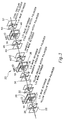
- Figure 3 is a 3-D exploded view of a picture element within the preferred subtractive color liquid crystal display with circular notch polarizers and retarder films.
- Figure 4 is a truth table for a picture element within the twisted nematic subtractive color liquid crystal display utilizing circular notch polarizers and retarder films.
- Figure 5 is a comparative transmission diagram for white light of a picture element with either notch polarizers or dichroic polarizers used to obtain approximately equivalent color gamuts.
- Figure 6 is a comparative transmission diagram for red light of a picture element with either notch polarizers or dichroic polarizers.
- Figure 7 transmission diagram for is a comparative transmission diagram for green light of a picture element with either notch polarizers or dichroic polarizers.
- Figure 8 transmission diagram for is a comparative transmission diagram for blue light of a picture element with either notch polarizers or dichroic polarizers.
- Figure 9 is a chromaticity diagram comparing the NTSC standard with dichroic polarizer and notch polarizer subtractive color systems.
- Figure 10 is a transmission diagram comparing the performance of a dichroic red filter and a notch red filter.
- Figure 11 shows the output spectrum of a broad band lamp.
- Figures 12 shows the output spectrum of a filter tuned broad band lamp.
- Figures 13a shows the output spectrum of a triband light source.
- Figures 14a-d are transmission diagrams showing the performance of a single layer circular notch polarizer as its thickness is increased.
- Figure 15 shows the construction of a multiple layer notch polarizer.
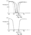
- Figures 16a and b are transmission diagrams showing the performance of multiple layer notch polarizers.
- Figures 17a and 17b are transmission diagrams showing the performance of a combination of dichroic and notch polarizers.
- Figure 18a is a graph the notch filters tuned to primary color peaks for straight on viewing and Figure 18b is a graph showing the width of the notches for angular viewing.
- FIGS 1A and 1B illustrate two commonplace embodiments of spatial additive color information displays.
- the typical shadow mask cathode ray tube 100 such as is used in commercial colored television receivers and which is the predominant device for color information display, is shown.
- Full color is achieved with the shadow-mask color cathode ray tube by the spatial integration of luminous emissions from closely-spaced R, G and B phosphor dots 106, each of which is excited by an associated electron beam 102.
- the phosphor dots are positioned on the cathode ray tube face 104.
- Electron beams 102 are generated by a plurality of electron guns.
- the R, G and B phosphor dots 106 are arranged in pixel groups 105.
- the electron beams 102 exciting each phosphor dot of a pixel group 105 pass through an aperture associated with each pixel group 105 in the shadow mask 103. Note that the spatial integration of chromatic information is performed by the observers eye and not the display device, thus requiring the display device to possess sufficient resolution such that the individual primary color elements are not individually resolvable by the eye of the observer.
- FIG. 1B another full-color display device, which relies on spatial-additive color synthesis is shown.
- This display is generally referred to as an active-matrix addressed liquid crystal color matrix display. While the basic principles of image formation and color mixture are the same as those used in the shadow mask color cathode ray tube, the liquid crystal color matrix display 120 employs a liquid crystal material which serves as an electronically controlled light valve at each picture element individually to gate incident light through a microlayer of color filters (typically R, G and B).
- Backlight 130 is transmitted through polarizing material 127. The backlight is then transmitted through the glass substrate 126 upon which our positioned thin film transistors 128.
- Liquid crystal material 125 is contained between glass substrate 126 and common (transparent) electrode 123.
- each thin film resistor 128 Associated with each thin film resistor 128 is a filter 124.
- the thin film transistor 128 controls the intensity of light transmitted through the associated filter 124.
- Three filters (R, G and B) 128 form an image pixel. The filtered light is then transmitted through glass substrate 122 and polarizing unit 121.
- FIG. 2 shows conceptually the structure for a subtractive color liquid crystal display.
- Light source 2 emits light which is incident upon the RGB subtractive stack 8.
- the stack 8 is made up of three separate color filters 10, 12 and 14. Each of the filters selectively removes a portion of the visible spectrum from the light emitted by light source 2.
- yellow filter 10 acts to remove blue light
- cyan filter 12 acts to remove red light
- magenta filter 14 acts to remove green light.
- individual picture elements 11 which can be turned on and off depending on the output desired. By manipulating the individual picture elements within the filters 10, 12 and 14 a color image is generated.
- the present invention incorporates subtractive color technology into a liquid crystal display.
- each display is made up of many individual picture elements.
- a detailed view of a picture element for one embodiment of the display is shown in Figure 3.
- the picture element 20 is comprised of three active switching elements 28, 38, and 48 with color notch polarizers located on either side. The combination of these elements forms a stacked structure.
- Each active switching element is comprised of two transparent electrodes with liquid crystal contained between.
- the liquid crystal used in the preferred embodiment of the invention is of the twisted nematic (TN) although super twisted nematic (STN) liquid crystal may also be used. The liquid crystal twists the polarity of incident light upon the element when no voltage is applied across the electrodes.
- TN twisted nematic
- STN super twisted nematic
- the incident light When a voltage is present, the incident light is allowed to pass unchanged in its polarity.
- Adjacent to switching element 28 is yellow circular polarizer 22 with 1/4 wave retarder plate 24.
- the combination of yellow circular polarizer 22 and 1/4 wave retarder plate 24 act as a linear polarizer for blue light.
- the quarter wave retarder plate 30 converts the linearly polarized blue light back to circularly polarized light, where the direction of polarization is right handed or left handed depending on the entrance direction of the linearly polarized blue light exiting the twisted nematic liquid crystal (on or off) and entering the retarder plate 30.
- the circularly polarized blue light exiting the opposite side retarder is either transmitted (passed) or reflected (extinguished) depending on whether the handedness is the same or opposite that of retarder plate 30.
- the combination of the polarizers, 1/4 wave retarder plates, and switching element act as a selective filter for blue light.
- magenta circular polarizer 34 and 1/4 wave retarder plate 36 This combination acts as a linear polarizer for green light.
- 1/4 wave retarder plate 40 On the opposite side of switching element 38 is 1/4 wave retarder plate 40 and magenta circular polarizer 42.
- the combination of 1/4 wave retarder plates 36 and 40 and magenta circular polarizers 34 and 42 act as a selective filter, depending on the state of switching element 38, to either extinguish or pass green light.
- cyan circular polarizer 44 and 1/4 wave retarder plate 46 This combination acts as a linear polarizer for red light.
- 1/4 wave retarder plate 50 and cyan circular polarizer 52 Opposite the switching element are 1/4 wave retarder plate 50 and cyan circular polarizer 52.
- the combination of 1/4 wave retarder plates 46 and 50 and polarizers 44 and 52 act as a selective filter, depending on the state of switching element 48, to either pass or extinguish red light.
- the filters can be in any sequence, and the order shown in Figure 3 is by no means a limitation.
- the truth table tracks the polarization and modulation of light through the subtractive color display assembly.
- Unpolarized white (RGB) light is the entrance light medium.
- Crossed arrows indicates non-polarized light.
- Linear polarized light is indicated by a direction arrow for X and Y polarized light.
- a black dot indicates extinction of color.
- the order of color in each group of three symbols is R,G,B.
- the cyan magenta and yellow circular polarizers circular polarize red, green and blue respectively. These polarizers pass right handed circular polarized light and block (reflect) left handed circular polarized light.
- Quarter wave retarders convert circular polarized colors to linear polarized prior to entering each twisted nematic liquid crystal cell.
- the liquid crystal cell rotates the linear polarization 90 degrees in the offstate, and does not rotate in the field on state.
- the output quarter wave retarders are aligned such that Y linear polarized colors become circular polarized right handed, and X linear polarized colors become circular polarized left handed.
- the right handed circular polarized colors R, G, and B are transmitted by the output circular notch polarizers C, M, and Y respectively, and the left handed circular polarized colors R, G and B are extinguished (reflected) by the output circular notch polarizers C, M and Y respectively.
- Each subtractive color modulation element in this subtractive color series is of the order: right handed circular polarizer, quarter wave retarder, twisted nematic light valve, quarter wave retarder, right handed circular polarizer.
- a left handed circular notch polarizer series, as well as a series combination of left and right handed circular notch polarizer can also be constructed with equal success. All of the above series can be oriented for normally colored or normally white as desired.
- the light which is incident upon the picture element is white containing elements of all three primary colors. As the light travels through the picture element, the different primary colors are either subtracted or allowed to pass depending on the desired color to be transmitted to the viewer.
- the polarizer order is such that the magenta polarizers are first, the yellow polarizers are second, and the cyan polarizers are third. As was described above, the magenta polarizers polarize green light, the yellow polarizers polarize blue light, and the cyan polarizers polarize red light. According to the truth table, when white light strikes the magenta circular polarizer, the green component of the light is circularly polarized while the other components of the light passed unchanged.
- the circularly polarized green light is linearly polarized in one direction. If a charge is across the liquid crystal cell, the polarization of the light passing through will be unchanged, while if the liquid crystal cell is off, the polarization of the light is rotated 90°.
- the 1/4 wave plate on the opposite side of the liquid crystal cell will circularly polarize in the counter clockwise direction the green light polarized in a first direction, and circularly polarize in the clockwise direction green light polarized in a second direction.
- the green light which is circularly polarized in the counter clockwise direction is blocked while the green light which is polarized in the clock wise direction is allowed to pass.
- the yellow and cyan notch polarizers perform the same function on the red and blue light, respectively. These components of the incident light are either filtered completely or allowed to pass. As is seen at the top of the truth table, all eight basic combinations of light (primary, subtractive, white, and black) are allowed to exit the picture element. However, this does not take into account various shading techniques and gray scale which can be created by partially turning on and off those liquid crystal cells.
- the truth table merely shows the basic operation of a particular picture element in the subtractive liquid crystal display to yield full color.
- cholesteric liquid crystal silicones are used in the construction of the circular notch polarizers.
- Polarizers fabricated from cholesteric liquid crystal silicones are almost ideal polarizers for TN LCD subtractive color displays. These polarizers are commonly called notch polarizers because of the very steep and isolated polarization bands, which polarize a specific wavelength region of the visible spectrum. Contrary to conventional polarizing filters employing dye or iodine, cholesteric filters do not absorb light, but instead reflect the polarized light and allows the rest to pass.
- Liquid crystal silicones are side chain polymers with a siloxane ring as a backbone and mesogenic side groups to induce a liquid crystalline phase. Pitch, helicity, and reflection color are determined by type and ratio of mesogenic side groups.
- the liquid crystal silicones are available from the Wacker Corporation of Germany.
- the cholesteric liquid crystal silicone (CLCS) mixtures are formulated to adjust the chirality (cholesteric twist) for characteristic polarization notch wavelength locations. Using suitable materials, the CLCS can be crosslinked thermally or by UV-irradiation.
- the CLCS linear polarizers are tuned to a particular wavelength and then bonded to a 1/4 wave film tailored for specific 1/4 wave retardation for each color (red, green, and blue wavelengths).
- Stretch polymer films are selected for the 1/4-wave length retardation of optimized red, green, and blue CLCS circular notched polarization reflecting films, which are optimally tuned to the particular lamp spectra output. This will maximize the linear conversation of circular polarized light, for high linear polarization efficiency and higher transmission with respect to the linear polarization conversion.
- Achromatic (wide band) retarders can also be used.
- the 1/4-wave retarders serve to convert circular polarized light to linear polarized light, and linear polarized light to circular polarized light.
- the CLCS layer thickness is calibrated for optimization of notched polarization band-width, to maximize out of band transmission, minimize minor overlap of the cyan notch with the magenta notch, and the magenta notch with the yellow notch, for the illumination used (wide or narrow band).
- notch polarizers described herein are that instead of filtering large portions of the incident light these filters sharply remove an isolated color band.
- Films made of cholesteric liquid crystal silicones efficiently reflect a isolated band of circularly polarized light (50%) as a single-handedness of chirality, while transmitting approximately 50% of light as light efficiently circularly polarized in the opposite chiral-handedness in a narrow notch band-width.
- These notched polarizers transmit 80-100 percent unpolarized light outside the isolated polarization band-width, which is almost ideal polarizer behavior and much superior to that of dichroic polarizers which are commercially available.
- Figures 5 through 8 are a comparison of light transmission through picture elements which use either the notch circular polarizers described herein or commercial dichroic polarizers.
- the illumination source is a triband lamp.
- Figure 5 shows the transmission of white light through the picture elements of both types.
- the dashed line is the notch polarizer white and the solid line is the dichroic white.
- the transmission of white light through the circular notch polarizers is many times greater than the amount of white light transmitted through the dichroic filters for equivalent color gamut.
- Figure 6 shows the situation where red light is emitted from the picture element. With the notch filters, the blue and green components of the incident light are nearly completely removed, however the transmission of the red light is over twice what it would be with the dichroic filters.
- This graph also clearly shows the narrow and steep bands of light which are filtered by the circular notched polarizers. Spectra between the blue and green, and the green and red, is allowed to pass through the picture element.
- Figures 7 and 8 show the performance of the picture element for blue and green light respectively. Once again the narrow and steep bands of filtered light are apparent.
- the estimated color gamut for the notch polarizer is compared with the color gamut for dichroic polarizers and with the NTSC standard in the chromaticity diagram shown in Figure 9.
- the chromaticity diagram displays three color gamuts. The first is a twisted nematic subtractive color display for perfected color gamut with dichroic dye color sheet polarizers and other dichroic dye type polarizers. The second is the NTSC Standard characteristic of a CRT.
- the third is a twisted nematic subtractive color display utilizing circular notch polarizers, quarter wave retarders, and a tuned light source.
- the color gamuts are shown in CIE 1976 chromaticity coordinates.
- the notch polarizer color gamut is the largest with more available color hues.
- FIG. 10 is a transmission diagram showing the filtering of the color red with a notch filter versus a conventional dichroic filter.
- the circular notch polarizer filters red light only in a narrow band with very little overlap into other regions of the visible spectrum.
- the conventional dichroic filters With the conventional dichroic filters, the red light is filtered, but there is significant filtering of green light. This has a detrimental affect on the brightness and contrast of the color display.
- the advantages of the color circular notch polarizers in a subtractive color display there must be some sort of optical tuning between the light source and the polarization bandwidth for each of the notch polarizers.
- the polarization bandwidth must be broad enough to filter any light emitted by the light source.
- the advantages of circular color notch polarizers can be used with a light source that is tuned to emit light in narrow bands of the three primary colors, is filter tuned to emit light over broader bands of the three primary colors, or emits light over a broad-band.
- Figure 11 is a graph of the output of a typical broad-band lamp. With this light source, light across the visible spectrum is emitted. In order to improve performance of the subtractive color display, it is advantageous to emit light whose components are more like those shown in Figure 12.
- This particular graph is of a 300-watt broad-band lamp tuned to red, green, and blue peaks with notch filters. These notch filters can be incorporated as part of the lamp.
- the notch filters can be made of liquid crystal silicones as described above, or commercially available multidielectric interference filters, or other dichroic materials. These notch filters are used to tune broad-band light sources such as a xenon arc lamp, a metal halide lamp, a tungsten halogen lamp, or a fluorescent lamp.
- Another is a triband light source such as individual lasers which emit primary colors in narrow wave bands.
- a triband light source such as three individual lasers, or a tuned broad band lamp can be used. With most types of light sources, the embodiment of the picture element shown in Figure 3 can be used.
- the output of a triband light source is shown in Figure 13a.
- the output consists of three narrow spikes of the primary colors whose magnitude and width are known. Since the triband light source does not emit any light between the primary color peaks, a single layer of the liquid crystal silicones is tuned to provide the necessary selective filtering.
- Figure 13a shows in particular the notch polarizer positioning and color control for a tri-band lamp with narrow isolated peaks when collimated light is used for illumination, and no direct view or viewing cone of illumination is desired.
- Figure 16a shows in particular, portions of the incident light filtered by each of the liquid crystal silicone layers.
- layer 62 may be optimized to polarize light in the band from 500 to 540 nanometers, while layer 64 may be tuned from 540 to 580 nanometers, and finally, layer 68 may be tuned to filter in the region of 560 to 600 nanometers.
- the overlap between the polarizers is not a problem and the layers are optimized to match the output of a particular light source.
- the composite for all layers is shown in Figure 16b. Many of these liquid silicone layers can be used in order to provide the desired amount of filtering.
- the circular notch polarizers are employed in conjunction with dichroic filters.
- dichroic filter In cases where broadband light sources are employed it is necessary to use dichroic filter in order to filter light over a wide spectral range.
- the solid line shows the output of a typical dichroic filter for light between 400 and 500 nanometers. With a typical dichroic filter there can be significant leakage of light in the particular portion of the spectrum which is to be filtered. In Figure 17a significant leakage is shown in the 450 nanometer range.
- circular notch polarizers are used in conjunction with the dichroic filters to correct any leakage.
- the dash line and the circular dash line are the portions of the spectrum between 400 and 500 nanometers removed by the circular notch polarizers. As seen in Figure 17b, when the circular notch polarizers are used in conjunction with the dichroic filters, any leakage from the dichroic filter can be eliminated without reducing the overall transmission quality of the dichroic filter.
- the notch position shown in Figure 18a must be shifted (expanded).
- the notch width can be expanded by any of the methods described above.
- Shown in Figure 18b is the shifted notch position for the same design as Figure 18a but for light passing through at plus or minus 40 degrees from notch polarizer layer normal.
- the notch shifts to lower wavelengths but stays aligned with lamp peak, and does not attenuate adjacent peaks due to correct separation between peaks.
- This design prevents a chromaticity shift for angular light output.
- narrower lamp peaks such as a tri-band lamp or laser, a similar design but with narrower notch polarizer bandwidths can be utilized.
Landscapes
- Physics & Mathematics (AREA)
- Nonlinear Science (AREA)
- Mathematical Physics (AREA)
- Chemical & Material Sciences (AREA)
- Crystallography & Structural Chemistry (AREA)
- General Physics & Mathematics (AREA)
- Optics & Photonics (AREA)
- Liquid Crystal (AREA)
- Plural Heterocyclic Compounds (AREA)
- Agricultural Chemicals And Associated Chemicals (AREA)
Claims (3)
- Subtraktives Flüssigkristallfarbdisplay, umfassend:
ein abgestimmtes Beleuchtungsmittel (2); und
mehrere Bildelemente (11, 20), wobei jedes der Bildelemente folgendes umfaßt:wobei der Eintritts- und der Austrittskerbpolarisator jeweils einen dichroitischen Folienfarbpolarisator, einen Zirkularkerbpolarisator (22, 32, 34, 42, 44, 52) und eine Viertelwellen-Phasenplatte (24, 30, 36, 40, 46, 50) umfaßt.ein erstes, zweites und drittes aktives Schaltelement (28, 38, 48), die relativ zu dem Beleuchtungsmittel (2) ausgerichtet sind und die die Polarisation von von dem Beleuchtungsmittel (2) einfallendem Licht gezielt drehen;einen ersten Eintrittskerbpolarisator neben dem ersten Schaltelement (28), der ein schmales Lichtband der ersten Primärfarbe (Rot, Grün und Blau) polarisiert;einen ersten Austrittskerbpolarisator neben dem ersten Schaltelement (28), der Licht der ersten Primärfarbe je nach der dem Licht durch das erste Schaltelement (28) erteilten Drehung blockiert oder durchläßt;einen zweiten Eintrittskerbpolarisator neben dem zweiten Schaltelement (38), der ein schmales Lichtband einer zweiten Primärfarbe polarisiert;einen zweiten Austrittskerbpolarisator neben dem zweiten Schaltelement (38), der Licht der zweiten Primärfarbe je nach der dem Licht durch das zweite Schaltelement (38) erteilten Drehung blockiert oder durchläßt;einen dritten Eintrittskerbpolarisator neben dem dritten Schaltelement (48), der ein schmales Lichtband der dritten Primärfarbe polarisiert;einen dritten Austrittskerbpolarisator neben dem dritten Schaltelement (48), der Licht der ersten Primärfarbe je nach der dem Licht durch das dritte Schaltelement (48) erteilten Drehung blockiert oder durchläßt; - Subtraktives Flüssigkristalldisplay nach Anspruch 1, bei dem der Zirkularkerbpolarisator (22, 32, 34, 42, 44, 52) aus abgestimmten vernetzten cholesterischen Flüssigkristallsilikonen aufgebaut ist.
- Subtraktives Flüssigkristalldisplay nach Anspruch 1 oder 2, bei dem die Zirkularkerbpolarisatoren (22, 32, 34, 42, 44, 52) abgestimmt sind, von den dichroitischen Folienfarbpolarisatoren ineffizient polarisiertes oder nicht polarisiertes Licht effizient zu polarisieren.
Applications Claiming Priority (3)
| Application Number | Priority Date | Filing Date | Title |
|---|---|---|---|
| US255031 | 1994-06-07 | ||
| US08/255,031 US5751385A (en) | 1994-06-07 | 1994-06-07 | Subtractive color LCD utilizing circular notch polarizers and including a triband or broadband filter tuned light source or dichroic sheet color polarizers |
| PCT/US1995/007098 WO1995034022A1 (en) | 1994-06-07 | 1995-06-05 | A subtractive color liquid crystal display utilizing circular notch polarizers |
Publications (2)
| Publication Number | Publication Date |
|---|---|
| EP0764289A1 EP0764289A1 (de) | 1997-03-26 |
| EP0764289B1 true EP0764289B1 (de) | 2000-08-16 |
Family
ID=22966550
Family Applications (1)
| Application Number | Title | Priority Date | Filing Date |
|---|---|---|---|
| EP95922209A Expired - Lifetime EP0764289B1 (de) | 1994-06-07 | 1995-06-05 | Subtraktive farbflüssigkristallanzeige mit zirkularen sperrpolisarisation |
Country Status (6)
| Country | Link |
|---|---|
| US (1) | US5751385A (de) |
| EP (1) | EP0764289B1 (de) |
| JP (1) | JPH10501349A (de) |
| CA (1) | CA2189780A1 (de) |
| DE (1) | DE69518420T2 (de) |
| WO (1) | WO1995034022A1 (de) |
Families Citing this family (53)
| Publication number | Priority date | Publication date | Assignee | Title |
|---|---|---|---|---|
| SG47360A1 (en) * | 1994-11-14 | 1998-04-17 | Hoffmann La Roche | Colour display with serially-connected lc filters |
| KR0176426B1 (ko) * | 1995-12-15 | 1999-05-01 | 윤종용 | 라이트 밸브와 이를 이용한 투사장치 |
| JP3032424U (ja) * | 1996-06-14 | 1996-12-24 | セイコー電子工業株式会社 | 液晶表示装置およびその液晶表示装置を備えた携帯機器 |
| JPH10115826A (ja) * | 1996-08-23 | 1998-05-06 | Seiko Epson Corp | 表示素子およびそれを用いた電子機器 |
| US6111700A (en) * | 1996-09-05 | 2000-08-29 | Fujitsu Limited | Optical display device having a reflection-type polarizer |
| US5949469A (en) * | 1997-06-10 | 1999-09-07 | Eastman Kodak Co | Fluorescent light source for liquid crystal display printing |
| US6891584B1 (en) * | 1998-10-28 | 2005-05-10 | Dai Nippon Printing Co., Ltd. | Liquid-crystal display |
| JP3424598B2 (ja) * | 1999-04-30 | 2003-07-07 | ノーリツ鋼機株式会社 | 焼付装置ならびにこれを備えた写真処理装置 |
| US6344887B1 (en) * | 1999-09-10 | 2002-02-05 | Yao-Dong Ma | Full spectrum reflective choleterics display employing circular polarizers with the same polarity but different disposition |
| JP2001100029A (ja) | 1999-09-29 | 2001-04-13 | Fujitsu General Ltd | 偏光カラーフィルタ及びこのフィルタを用いた映像投影装置 |
| AU2661501A (en) * | 2000-02-03 | 2001-08-14 | Rolic Ag | Colour switch |
| TWM272104U (en) * | 2000-05-19 | 2005-08-01 | United Radiant Technology Corp | Liquid crystal shutter display |
| US8487850B1 (en) * | 2000-06-05 | 2013-07-16 | Hewlett-Packard Development Company, L.P. | Multi-source LCD backlight for white balance adjustment |
| US6870523B1 (en) | 2000-06-07 | 2005-03-22 | Genoa Color Technologies | Device, system and method for electronic true color display |
| EP1203980A1 (de) * | 2000-11-03 | 2002-05-08 | Rolic AG | Schaltbarer Farbfilter |
| JP2004514165A (ja) * | 2000-11-17 | 2004-05-13 | ディープ ヴィデオ イメージング リミテッド | 表示装置スクリーンのマットから光学的に滑らかな表面への変更方法 |
| US7352488B2 (en) * | 2000-12-18 | 2008-04-01 | Genoa Color Technologies Ltd | Spectrally matched print proofer |
| NZ511255A (en) * | 2001-04-20 | 2003-12-19 | Deep Video Imaging Ltd | Multi-focal plane display having an optical retarder and a diffuser interposed between its screens |
| AU2002309213A1 (en) * | 2001-06-07 | 2002-12-16 | Genoa Technologies Ltd. | System and method of data conversion for wide gamut displays |
| US8289266B2 (en) * | 2001-06-11 | 2012-10-16 | Genoa Color Technologies Ltd. | Method, device and system for multi-color sequential LCD panel |
| CN100407276C (zh) * | 2001-06-11 | 2008-07-30 | 格诺色彩技术有限公司 | 用于彩色显示的设备、系统和方法 |
| US7714824B2 (en) * | 2001-06-11 | 2010-05-11 | Genoa Color Technologies Ltd. | Multi-primary display with spectrally adapted back-illumination |
| NZ514500A (en) | 2001-10-11 | 2004-06-25 | Deep Video Imaging Ltd | A multiplane visual display unit with a transparent emissive layer disposed between two display planes |
| EP1306717A1 (de) * | 2001-10-24 | 2003-05-02 | Rolic AG | Schaltbarer Farbfilter |
| US7015991B2 (en) * | 2001-12-21 | 2006-03-21 | 3M Innovative Properties Company | Color pre-filter for single-panel projection display system |
| AU2003208563A1 (en) * | 2002-01-07 | 2003-07-24 | Moshe Ben-Chorin | Electronic color display for soft proofing |
| US7742239B2 (en) * | 2002-03-17 | 2010-06-22 | Puredepth Limited | Method to control point spread function of an image |
| JP4799823B2 (ja) * | 2002-04-11 | 2011-10-26 | ジェノア・カラー・テクノロジーズ・リミテッド | 属性を向上させるカラー表示装置および方法 |
| US9137525B2 (en) * | 2002-07-15 | 2015-09-15 | Pure Depth Limited | Multilayer video screen |
| WO2004010407A2 (en) * | 2002-07-24 | 2004-01-29 | Genoa Color Technologies Ltd. | High brightness wide gamut display |
| NZ521505A (en) | 2002-09-20 | 2005-05-27 | Deep Video Imaging Ltd | Multi-view display |
| TW562988B (en) * | 2002-12-10 | 2003-11-21 | Coretronic Corp | Multi-function projection system |
| DE602004014250D1 (de) | 2003-01-28 | 2008-07-17 | Genoa Color Technologies Ltd | Subpixel-anordnung für displays mit mehr als drei primärfarben |
| US20040164101A1 (en) * | 2003-02-20 | 2004-08-26 | Valois Sas | Fluid dispenser |
| JP3823972B2 (ja) * | 2003-05-09 | 2006-09-20 | セイコーエプソン株式会社 | 視角制御素子、表示装置、及び電子機器 |
| EP1660937A2 (de) * | 2003-08-04 | 2006-05-31 | Genoa Color Technologies Ltd. | Mehrfach-primärfarben-display |
| US7483095B2 (en) * | 2003-12-15 | 2009-01-27 | Genoa Color Technologies Ltd | Multi-primary liquid crystal display |
| US7495722B2 (en) | 2003-12-15 | 2009-02-24 | Genoa Color Technologies Ltd. | Multi-color liquid crystal display |
| EP2434488A3 (de) * | 2004-12-16 | 2012-05-30 | RealD Inc. | Verbund-Viertelwellenretarder für einen Lesekopf für optische Platten |
| US20060158668A1 (en) * | 2005-01-20 | 2006-07-20 | Eastman Kodak Company | Method and apparatus for increasing color gamut of a three color primary additive display device |
| US20080150882A1 (en) * | 2005-04-15 | 2008-06-26 | Koninklijke Philips Electronics, N.V. | Color Display Device and Method of Operating the Same |
| WO2007060672A2 (en) * | 2005-11-28 | 2007-05-31 | Genoa Color Technologies Ltd. | Sub-pixel rendering of a multiprimary image |
| DE102006050580A1 (de) * | 2006-10-26 | 2008-04-30 | Forschungszentrum Karlsruhe Gmbh | Optischer Isolator, Anordnung mit einem optischen Isolator, Verfahren zu dessen Herstellung und dessen Verwendung |
| JP2010537251A (ja) * | 2007-08-22 | 2010-12-02 | ピュアデプス リミテッド | マルチコンポーネントディスプレイのための中間ディフューザの位置の決定 |
| EP2491442A1 (de) * | 2009-10-24 | 2012-08-29 | 3M Innovative Properties Company | Reflektierender tauchpolarisator mit winkelverfeinerung in ausgewählten ebenen von interesse |
| KR101832509B1 (ko) * | 2009-10-24 | 2018-02-26 | 쓰리엠 이노베이티브 프로퍼티즈 컴파니 | 고 비축 반사율을 갖는 침지형 반사 편광기 |
| US8384851B2 (en) * | 2010-01-11 | 2013-02-26 | 3M Innovative Properties Company | Reflective display system with enhanced color gamut |
| US9116390B2 (en) | 2012-08-27 | 2015-08-25 | Microsoft Technology Licensing, Llc | Touch sensing liquid crystal display compatible with linearly polarized sunglasses |
| US10535292B2 (en) | 2014-06-17 | 2020-01-14 | Nato Pirtskhlava | One way display |
| US20160267851A1 (en) * | 2014-06-17 | 2016-09-15 | Nato Pirtskhlava | One Way Display |
| CN108051947B (zh) * | 2018-01-09 | 2024-04-12 | 河北工业大学 | 一种色域拓宽装置 |
| US11394934B2 (en) * | 2020-09-24 | 2022-07-19 | Qualcomm Incorporated | Binned anti-color pixel value generation |
| TWI828255B (zh) * | 2022-07-29 | 2024-01-01 | 張庭嘉 | 光學變色裝置 |
Family Cites Families (10)
| Publication number | Priority date | Publication date | Assignee | Title |
|---|---|---|---|---|
| US4073571A (en) * | 1976-05-05 | 1978-02-14 | Hughes Aircraft Company | Circularly polarized light source |
| US4726663A (en) * | 1986-11-14 | 1988-02-23 | Tektronix, Inc. | Switchable color filter with enhanced transmissivity |
| US5032007A (en) * | 1988-04-07 | 1991-07-16 | Honeywell, Inc. | Apparatus and method for an electronically controlled color filter for use in information display applications |
| JPH02272431A (ja) * | 1989-04-13 | 1990-11-07 | Seiko Instr Inc | 液晶装置 |
| US5122887A (en) * | 1991-03-05 | 1992-06-16 | Sayett Group, Inc. | Color display utilizing twisted nematic LCDs and selective polarizers |
| US5221982A (en) * | 1991-07-05 | 1993-06-22 | Faris Sadeg M | Polarizing wavelength separator |
| JP2704581B2 (ja) * | 1991-11-20 | 1998-01-26 | 株式会社半導体エネルギー研究所 | 画像表示装置 |
| US5295777A (en) * | 1992-12-23 | 1994-03-22 | Materials Research Corporation | Wafer transport module with rotatable and horizontally extendable wafer holder |
| US5325218A (en) * | 1992-12-31 | 1994-06-28 | Minnesota Mining And Manufacturing Company | Cholesteric polarizer for liquid crystal display and overhead projector |
| US5548422A (en) * | 1993-06-28 | 1996-08-20 | In Focus Systems, Inc. | Notch filters with cholesteric polarizers with birefringent film and linear polarizer |
-
1994
- 1994-06-07 US US08/255,031 patent/US5751385A/en not_active Expired - Fee Related
-
1995
- 1995-06-05 WO PCT/US1995/007098 patent/WO1995034022A1/en not_active Ceased
- 1995-06-05 EP EP95922209A patent/EP0764289B1/de not_active Expired - Lifetime
- 1995-06-05 CA CA002189780A patent/CA2189780A1/en not_active Abandoned
- 1995-06-05 JP JP8501253A patent/JPH10501349A/ja active Pending
- 1995-06-05 DE DE69518420T patent/DE69518420T2/de not_active Expired - Fee Related
Also Published As
| Publication number | Publication date |
|---|---|
| JPH10501349A (ja) | 1998-02-03 |
| WO1995034022A1 (en) | 1995-12-14 |
| DE69518420D1 (de) | 2000-09-21 |
| CA2189780A1 (en) | 1995-12-14 |
| US5751385A (en) | 1998-05-12 |
| DE69518420T2 (de) | 2000-12-14 |
| EP0764289A1 (de) | 1997-03-26 |
Similar Documents
| Publication | Publication Date | Title |
|---|---|---|
| EP0764289B1 (de) | Subtraktive farbflüssigkristallanzeige mit zirkularen sperrpolisarisation | |
| WO1995034022A9 (en) | A subtractive color liquid crystal display utilizing circular notch polarizers | |
| US6273571B1 (en) | Display architectures using an electronically controlled optical retarder stack | |
| EP0898841B1 (de) | Farbselektive lichtmodulatoren | |
| US6452646B1 (en) | Optical retarder stack formed of multiple retarder sheets | |
| US5929946A (en) | Retarder stack for preconditioning light for a modulator having modulation and isotropic states of polarization | |
| JP3300642B2 (ja) | 画像表示装置 | |
| US6049367A (en) | Polarization manipulating device modulator with retarder stack which preconditions light for modulation and isotropic states | |
| US5032007A (en) | Apparatus and method for an electronically controlled color filter for use in information display applications | |
| US7511787B2 (en) | Color filters and sequencers using color-selective light modulators | |
| US6667784B2 (en) | Color filters, sequencers and displays using color selective light modulators | |
| US5841494A (en) | Transflective LCD utilizing chiral liquid crystal filter/mirrors | |
| KR100536924B1 (ko) | 광학표시시스템 및 광학시프트소자 | |
| KR100258048B1 (ko) | 직렬 연결된 엘씨 필터를 구비한 칼라 표시 장치 | |
| US6327093B1 (en) | Image display apparatus | |
| US5347378A (en) | Fast switching color filters for frame-sequential video using ferroelectric liquid crystal color-selective filters | |
| EP0708568B1 (de) | Projektionsfarbanzeigevorrichtung | |
| JP2008020921A (ja) | 光モジュレータおよびシーケンサー | |
| JP3923689B2 (ja) | カラーシャッタ及びカラー画像表示方法 | |
| WO1997001792A1 (en) | Full color display of subtractive color type | |
| JPH05264945A (ja) | 液晶波長分波装置 | |
| HK1011089A (en) | Coloured display with electrically controllable liquid crystal filters disposed in series |
Legal Events
| Date | Code | Title | Description |
|---|---|---|---|
| PUAI | Public reference made under article 153(3) epc to a published international application that has entered the european phase |
Free format text: ORIGINAL CODE: 0009012 |
|
| 17P | Request for examination filed |
Effective date: 19961126 |
|
| AK | Designated contracting states |
Kind code of ref document: A1 Designated state(s): DE FR GB |
|
| 17Q | First examination report despatched |
Effective date: 19971015 |
|
| GRAG | Despatch of communication of intention to grant |
Free format text: ORIGINAL CODE: EPIDOS AGRA |
|
| GRAG | Despatch of communication of intention to grant |
Free format text: ORIGINAL CODE: EPIDOS AGRA |
|
| GRAH | Despatch of communication of intention to grant a patent |
Free format text: ORIGINAL CODE: EPIDOS IGRA |
|
| GRAH | Despatch of communication of intention to grant a patent |
Free format text: ORIGINAL CODE: EPIDOS IGRA |
|
| GRAA | (expected) grant |
Free format text: ORIGINAL CODE: 0009210 |
|
| AK | Designated contracting states |
Kind code of ref document: B1 Designated state(s): DE FR GB |
|
| REF | Corresponds to: |
Ref document number: 69518420 Country of ref document: DE Date of ref document: 20000921 |
|
| ET | Fr: translation filed | ||
| PLBE | No opposition filed within time limit |
Free format text: ORIGINAL CODE: 0009261 |
|
| STAA | Information on the status of an ep patent application or granted ep patent |
Free format text: STATUS: NO OPPOSITION FILED WITHIN TIME LIMIT |
|
| 26N | No opposition filed | ||
| REG | Reference to a national code |
Ref country code: GB Ref legal event code: IF02 |
|
| PGFP | Annual fee paid to national office [announced via postgrant information from national office to epo] |
Ref country code: GB Payment date: 20040505 Year of fee payment: 10 |
|
| PGFP | Annual fee paid to national office [announced via postgrant information from national office to epo] |
Ref country code: DE Payment date: 20040630 Year of fee payment: 10 |
|
| PGFP | Annual fee paid to national office [announced via postgrant information from national office to epo] |
Ref country code: FR Payment date: 20050602 Year of fee payment: 11 |
|
| PG25 | Lapsed in a contracting state [announced via postgrant information from national office to epo] |
Ref country code: GB Free format text: LAPSE BECAUSE OF NON-PAYMENT OF DUE FEES Effective date: 20050605 |
|
| PG25 | Lapsed in a contracting state [announced via postgrant information from national office to epo] |
Ref country code: DE Free format text: LAPSE BECAUSE OF NON-PAYMENT OF DUE FEES Effective date: 20060103 |
|
| GBPC | Gb: european patent ceased through non-payment of renewal fee |
Effective date: 20050605 |
|
| REG | Reference to a national code |
Ref country code: FR Ref legal event code: ST Effective date: 20070228 |
|
| PG25 | Lapsed in a contracting state [announced via postgrant information from national office to epo] |
Ref country code: FR Free format text: LAPSE BECAUSE OF NON-PAYMENT OF DUE FEES Effective date: 20060630 |
|
| P01 | Opt-out of the competence of the unified patent court (upc) registered |
Effective date: 20230525 |