EP0764038B1 - Vorrichtung zur messung der kontraktionskraft des herzens - Google Patents
Vorrichtung zur messung der kontraktionskraft des herzens Download PDFInfo
- Publication number
- EP0764038B1 EP0764038B1 EP95921070A EP95921070A EP0764038B1 EP 0764038 B1 EP0764038 B1 EP 0764038B1 EP 95921070 A EP95921070 A EP 95921070A EP 95921070 A EP95921070 A EP 95921070A EP 0764038 B1 EP0764038 B1 EP 0764038B1
- Authority
- EP
- European Patent Office
- Prior art keywords
- acceleration
- transducer
- catheter
- transducers
- approximately
- Prior art date
- Legal status (The legal status is an assumption and is not a legal conclusion. Google has not performed a legal analysis and makes no representation as to the accuracy of the status listed.)
- Expired - Lifetime
Links
- 230000000747 cardiac effect Effects 0.000 title claims abstract description 30
- 238000012544 monitoring process Methods 0.000 title claims abstract description 8
- 230000001133 acceleration Effects 0.000 claims abstract description 119
- 210000004165 myocardium Anatomy 0.000 claims abstract description 7
- 238000003780 insertion Methods 0.000 claims abstract description 3
- 230000037431 insertion Effects 0.000 claims abstract description 3
- 230000004913 activation Effects 0.000 claims description 28
- 239000002184 metal Substances 0.000 claims description 24
- 238000012545 processing Methods 0.000 claims description 21
- 239000000872 buffer Substances 0.000 claims description 19
- 238000005070 sampling Methods 0.000 claims description 14
- 239000003990 capacitor Substances 0.000 claims description 11
- 238000000576 coating method Methods 0.000 claims description 10
- 239000000463 material Substances 0.000 claims description 9
- 239000011248 coating agent Substances 0.000 claims description 8
- 239000004020 conductor Substances 0.000 claims description 6
- 230000001419 dependent effect Effects 0.000 claims description 5
- 230000004044 response Effects 0.000 claims description 5
- 125000004122 cyclic group Chemical group 0.000 claims description 4
- 230000002861 ventricular Effects 0.000 claims description 3
- 239000000853 adhesive Substances 0.000 claims description 2
- 230000001070 adhesive effect Effects 0.000 claims description 2
- 230000008878 coupling Effects 0.000 claims description 2
- 238000010168 coupling process Methods 0.000 claims description 2
- 238000005859 coupling reaction Methods 0.000 claims description 2
- 238000001914 filtration Methods 0.000 claims description 2
- 239000012530 fluid Substances 0.000 claims description 2
- 230000000717 retained effect Effects 0.000 claims description 2
- 230000035939 shock Effects 0.000 claims description 2
- 238000013016 damping Methods 0.000 claims 4
- 239000013013 elastic material Substances 0.000 claims 1
- 238000011065 in-situ storage Methods 0.000 claims 1
- 230000002045 lasting effect Effects 0.000 claims 1
- 238000013017 mechanical damping Methods 0.000 claims 1
- 229920006395 saturated elastomer Polymers 0.000 claims 1
- 239000007779 soft material Substances 0.000 claims 1
- 238000001994 activation Methods 0.000 description 26
- 238000005259 measurement Methods 0.000 description 14
- 238000000034 method Methods 0.000 description 11
- 230000006870 function Effects 0.000 description 8
- 230000008602 contraction Effects 0.000 description 6
- 230000000694 effects Effects 0.000 description 5
- 238000002474 experimental method Methods 0.000 description 4
- 230000000638 stimulation Effects 0.000 description 4
- 238000007920 subcutaneous administration Methods 0.000 description 4
- 238000010586 diagram Methods 0.000 description 3
- 238000006073 displacement reaction Methods 0.000 description 3
- 238000005516 engineering process Methods 0.000 description 3
- 238000001802 infusion Methods 0.000 description 3
- 230000029058 respiratory gaseous exchange Effects 0.000 description 3
- 230000000284 resting effect Effects 0.000 description 3
- 230000000630 rising effect Effects 0.000 description 3
- 230000003068 static effect Effects 0.000 description 3
- 238000012360 testing method Methods 0.000 description 3
- 230000002457 bidirectional effect Effects 0.000 description 2
- 230000005540 biological transmission Effects 0.000 description 2
- 239000000919 ceramic Substances 0.000 description 2
- 238000007796 conventional method Methods 0.000 description 2
- 239000003814 drug Substances 0.000 description 2
- 229940079593 drug Drugs 0.000 description 2
- 238000000605 extraction Methods 0.000 description 2
- 230000000670 limiting effect Effects 0.000 description 2
- 230000002107 myocardial effect Effects 0.000 description 2
- 230000037081 physical activity Effects 0.000 description 2
- 230000009467 reduction Effects 0.000 description 2
- 230000001052 transient effect Effects 0.000 description 2
- XUIMIQQOPSSXEZ-UHFFFAOYSA-N Silicon Chemical compound [Si] XUIMIQQOPSSXEZ-UHFFFAOYSA-N 0.000 description 1
- 239000004809 Teflon Substances 0.000 description 1
- 229920006362 Teflon® Polymers 0.000 description 1
- 238000010521 absorption reaction Methods 0.000 description 1
- 230000001154 acute effect Effects 0.000 description 1
- 230000002411 adverse Effects 0.000 description 1
- 230000003321 amplification Effects 0.000 description 1
- 238000004458 analytical method Methods 0.000 description 1
- 238000004422 calculation algorithm Methods 0.000 description 1
- 239000002775 capsule Substances 0.000 description 1
- 210000000748 cardiovascular system Anatomy 0.000 description 1
- 229910010293 ceramic material Inorganic materials 0.000 description 1
- 230000008859 change Effects 0.000 description 1
- 238000012512 characterization method Methods 0.000 description 1
- 238000006243 chemical reaction Methods 0.000 description 1
- 230000002301 combined effect Effects 0.000 description 1
- 239000002131 composite material Substances 0.000 description 1
- 238000010276 construction Methods 0.000 description 1
- 238000013480 data collection Methods 0.000 description 1
- 230000007423 decrease Effects 0.000 description 1
- 230000003247 decreasing effect Effects 0.000 description 1
- 230000001862 defibrillatory effect Effects 0.000 description 1
- 238000013461 design Methods 0.000 description 1
- 230000005284 excitation Effects 0.000 description 1
- 230000036541 health Effects 0.000 description 1
- 230000010247 heart contraction Effects 0.000 description 1
- 210000005003 heart tissue Anatomy 0.000 description 1
- 210000003709 heart valve Anatomy 0.000 description 1
- 239000011810 insulating material Substances 0.000 description 1
- 230000010354 integration Effects 0.000 description 1
- 230000003993 interaction Effects 0.000 description 1
- 210000005240 left ventricle Anatomy 0.000 description 1
- 230000007774 longterm Effects 0.000 description 1
- 238000005459 micromachining Methods 0.000 description 1
- 210000003205 muscle Anatomy 0.000 description 1
- 238000003199 nucleic acid amplification method Methods 0.000 description 1
- 230000003071 parasitic effect Effects 0.000 description 1
- 238000011458 pharmacological treatment Methods 0.000 description 1
- 230000008569 process Effects 0.000 description 1
- 230000002829 reductive effect Effects 0.000 description 1
- 238000011160 research Methods 0.000 description 1
- 239000012858 resilient material Substances 0.000 description 1
- 230000001020 rhythmical effect Effects 0.000 description 1
- 230000035945 sensitivity Effects 0.000 description 1
- 229910052710 silicon Inorganic materials 0.000 description 1
- 239000010703 silicon Substances 0.000 description 1
- 230000004936 stimulating effect Effects 0.000 description 1
- 230000007704 transition Effects 0.000 description 1
- 210000001835 viscera Anatomy 0.000 description 1
Images


Classifications
-
- A—HUMAN NECESSITIES
- A61—MEDICAL OR VETERINARY SCIENCE; HYGIENE
- A61N—ELECTROTHERAPY; MAGNETOTHERAPY; RADIATION THERAPY; ULTRASOUND THERAPY
- A61N1/00—Electrotherapy; Circuits therefor
- A61N1/18—Applying electric currents by contact electrodes
- A61N1/32—Applying electric currents by contact electrodes alternating or intermittent currents
- A61N1/36—Applying electric currents by contact electrodes alternating or intermittent currents for stimulation
- A61N1/372—Arrangements in connection with the implantation of stimulators
- A61N1/37211—Means for communicating with stimulators
-
- A—HUMAN NECESSITIES
- A61—MEDICAL OR VETERINARY SCIENCE; HYGIENE
- A61B—DIAGNOSIS; SURGERY; IDENTIFICATION
- A61B5/00—Measuring for diagnostic purposes; Identification of persons
- A61B5/0002—Remote monitoring of patients using telemetry, e.g. transmission of vital signals via a communication network
- A61B5/0031—Implanted circuitry
-
- A—HUMAN NECESSITIES
- A61—MEDICAL OR VETERINARY SCIENCE; HYGIENE
- A61B—DIAGNOSIS; SURGERY; IDENTIFICATION
- A61B5/00—Measuring for diagnostic purposes; Identification of persons
- A61B5/48—Other medical applications
- A61B5/4836—Diagnosis combined with treatment in closed-loop systems or methods
- A61B5/4839—Diagnosis combined with treatment in closed-loop systems or methods combined with drug delivery
-
- A—HUMAN NECESSITIES
- A61—MEDICAL OR VETERINARY SCIENCE; HYGIENE
- A61B—DIAGNOSIS; SURGERY; IDENTIFICATION
- A61B5/00—Measuring for diagnostic purposes; Identification of persons
- A61B5/68—Arrangements of detecting, measuring or recording means, e.g. sensors, in relation to patient
- A61B5/6846—Arrangements of detecting, measuring or recording means, e.g. sensors, in relation to patient specially adapted to be brought in contact with an internal body part, i.e. invasive
- A61B5/6879—Means for maintaining contact with the body
- A61B5/6882—Anchoring means
-
- A—HUMAN NECESSITIES
- A61—MEDICAL OR VETERINARY SCIENCE; HYGIENE
- A61N—ELECTROTHERAPY; MAGNETOTHERAPY; RADIATION THERAPY; ULTRASOUND THERAPY
- A61N1/00—Electrotherapy; Circuits therefor
- A61N1/18—Applying electric currents by contact electrodes
- A61N1/32—Applying electric currents by contact electrodes alternating or intermittent currents
- A61N1/36—Applying electric currents by contact electrodes alternating or intermittent currents for stimulation
- A61N1/362—Heart stimulators
- A61N1/365—Heart stimulators controlled by a physiological parameter, e.g. heart potential
- A61N1/36514—Heart stimulators controlled by a physiological parameter, e.g. heart potential controlled by a physiological quantity other than heart potential, e.g. blood pressure
- A61N1/36542—Heart stimulators controlled by a physiological parameter, e.g. heart potential controlled by a physiological quantity other than heart potential, e.g. blood pressure controlled by body motion, e.g. acceleration
Definitions
- This invention relates to apparatus for monitoring cardiac contractility.
- a particular embodiment of the invention is suitable for application in pacemakers and in defibrillators, to permit the collection via telemetry of data relating to myocardial contractility and to monitor and control pharmacological treatment, provided either by infusion or by conventional methods.
- Acceleration sensors have also already been used as sensors in an implantable system, and there are rate-responsive electronic stimulators whose control is based on the measurement of vibrations in the 3-70 Hz band, in Medtronic's Activitrax, or of vibrations below 8 Hz in CPI's Excel.
- these sensors are disposed in the subcutaneous control unit, and are therefore sensitive only to vibrations and inertial forces transmitted through and to the whole body, and do not pick up the acceleration generated autonomously by the myocardium during the heart's operating cycle.
- the low-frequency component of the said signal lying approximately between zero and 15 Hz, is significantly affected by the movement of the part of the heart on which the measurement is being made, owing to the combined effect of the displacement of the endocardial walls which participate in the contraction and in the total movement of the cardiac body, as a reaction to the ejection phase, as a variation due to a change in posture or to respiration, and as an effect combined with other mechanical influences on the whole cardiac body.
- the band above 100 Hz may also be a source of errors since, during the phases of ejection and of opening and closing of the heart valves, signals at frequencies above 100 Hz may sometimes occur, depending solely on the flow dynamics and on the valve dynamics, and that their amplitude may be far greater than that of the vibrations generated in the isovolumetric contraction phase.
- apparatus for monitoring cardiac contractility comprising a catheter having a tip for insertion into a ventricle of the heart muscle, said catheter containing at or proximate its tip an acceleration transducer responsive to the natural heart acceleration to provide an acceleration signal via said catheter to signal processing means (9), characterised in that the signal processing means and/or the acceleration transer is or are arranged to suppress frequencies outside the range from 15 Hz to 100 Hz.
- the accelerometric system described in EP-A-0515319 further does not allow the real endocardial acceleration to be measured properly during the cardiac cycle, for the following reasons:
- the acceleration transducer is responsive to acceleration in any spatial direction.
- a first multiaxial transducer comprises an assembly of three uniaxial acceleration transducers. Each has an upper band limit which for mechanical reasons is limited to approximately 100 Hz.
- the transducers are orientated perpendicularly to each other and located in the tip of the catheter where there is also mounted an integrated electronic circuit enabling a master control unit to receive the three signals of the transducers in successive time intervals.
- a time interval of the order of approximately loo microseconds is used, in a ratio of 1/30 to the sampling period which is typically approximately 3000 microseconds. This method of operation enables the estimated consumption of approximately 30 ⁇ A in the 100 microseconds of sampling to be decreased to a mean consumption of approximately 1 ⁇ A which is fully compatible with the present criteria of implantability.
- the data are transmitted along the catheter with a two-wire conductor of simple form.
- a two-wire conductor of simple form By using only 1/30 of the previously mentioned time for sampling, it is possible to use the said conductors and the catheter tip for any necessary functions of sensing electrophysiological signals, electrical stimulation, defibrillation, or other.
- an acceleration transducer comprising: a casing of piezoelectric or piezoresistive material provided on inner and outer surfaces with respective conductive coatings, the inner conductive coating being connected to an external contact which is electrically isolated from the outer conductive coating, and a seismic mass being provided inside the said casing body.
- a preferred embodiment of this transducer overcomes by mechanical means the problem of providing a signal dependent on acceleration, regardless of its direction, by using a transducer comprising two linked hemispherical caps within which is disposed a seismic mass of spherical form.
- the hemispherical caps are made of materials which exhibit the phenomenon of piezoelectricity when they are stressed radially by the seismic mass. Regardless of the direction of the inertial stress, the seismic mass will stress the caps of the transducer which will produce an electrical signal proportional to the stress.
- the electronic circuitry disposed in the tip of the catheter and associated with the said multiaxial accelerometer can be limited in this case to a simple impedance matching circuit which, when commanded by the master control unit, is activated for approximately 30 microseconds once every 3000 microseconds, permitting a significant reduction in current consumption, which will not exceed approximately 0.3 ⁇ A.
- the link from the transducer and its associated electronic circuit to the master control unit is a two-wire link and permits alternation between the phases of sampling of the accelerometer and those of sensing, pacing and defibrillation.
- the accelerometer may be characterized by a band limited mechanically at the top end to 100 Hz; otherwise, owing to the limited operating consumption mentioned previously, the signal picked up by the transducer without any mechanical band limitation, may be reconstructed accurately with an appropriate sampling frequency, for example of the order of approximately 1000 Hz, and the reconstructed signal can then be electronically filtered in the band of approximately 15-100 Hz, for the extraction of that part of the signal which represents cardiac contractility in the isovolumetric phase.
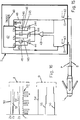
- a subcutaneous master control unit 9 is connected to a multiaxial acceleration transducer 2 located in the tip 1 of the catheter implanted in the heart, with the interposition of a mechanical damper 102 which mechanically limits to approximately 100 Hz the upper limit of the response frequency of the said acceleration transducer, in order to avoid significant sources of error.
- the master control unit 9 acts as an interface with the multiaxial acceleration transducer 2 and processes the acceleration signal to calculate the cardiac contractility in each cardiac cycle, within a frequency band between 15-100 Hz approximately, which also enables significant sources of error to be excluded.
- the master control unit 9 also acts as an interface, via bidirectional telemetry, with external monitoring and control devices 200, which permit the use of the said master control unit and the associated implantable device with the multiaxial acceleration transducer for any necessary electrical stimulation or defibrillation functions, or for monitoring the operation of implantable or external devices 300 used for infusion of drugs, which also have to operate, in association with other parameters if necessary, in relation to the measured values of cardiac contractility.
- the system may be limited to the transmission to the outside of the cardiac contractility detected by the multiaxial acceleration transducer.
- the use of bidirectional telemetry systems for monitoring and control of the non-invasive programming of all the functions of the system is also envisaged.
- Figure 2 shows that, according to a first embodiment of the invention, there is fixed in the tip 1 of the catheter an acceleration transducer of the triaxial type, formed by three uniaxial transducers 2x-2y-2z with an upper frequency limit mechanically limited to approximately 100 Hz, as stated previously, and perpendicular to each other, one of which is, for example, orientated along the axis of the catheter (see below).
- an acceleration transducer of the triaxial type formed by three uniaxial transducers 2x-2y-2z with an upper frequency limit mechanically limited to approximately 100 Hz, as stated previously, and perpendicular to each other, one of which is, for example, orientated along the axis of the catheter (see below).
- a triaxial piezoelectric transducer such as the Endevco Model 23 Picotriax Accelerometer, made with dimensions suitable for the purpose, or a piezoresistive triaxial transducer such as the Entran EGA3 made by Entran, also made with suitable dimensions by micromachining techniques.
- the transducers are associated with corresponding connection and amplification means 3x-3y-3z and with corresponding switches 4x-4y-4z whose outputs are connected to the gate of a MOS transistor 5 which acts as an output buffer.
- the number 6 indicates the load resistance of the devices 3x-3y-3z, while 7 and 8 indicate the electrically insulated wires which run inside the catheter and connect the components of the device in question, disposed inside the catheter, to the subcutaneously implanted master control unit 9.
- the circuit 10 branched from the buffer 5 and fitted in the tip 1 of the catheter performs timing functions, to make available in the single output conductor 8 the signals from the three uniaxial transducers 2x-2y-2z in distinct and successive time intervals.
- the master control unit 9 reconstructs within itself the three analog signals from the three acceleration transducers activated in a pulsed mode, amplifies them, filters them in a band from 15 to 100 Hz approximately, and measures within each cardiac cycle the peak-to-peak value of acceleration in the three directions considered, namely x-y-z. By filtering the three analog signals it is possible to select the cardiac vibrations characterising the isovolumetric pre-ejection phase.
- the master control unit 9 calculates the modulus of the three peak-to-peak values of acceleration relative to the cardiac cycle concerned, according to the following relation:
- Operations of the type stated above may be performed by suitably combining linear, logarithmic, and antilogarithmic amplifiers, or by means of digital calculation algorithms, with techniques known well to those skilled in the art.
- the object of implantability which, for example in the context of a pacemaker of the rate-responsive type, may be expressed as the availability of the catheter for any necessary functions of sensing and stimulation, requires the limitation of the percentage of time in which the conductors 7 and 8 are used for the measurement and transmission of the signals read by the multiaxial acceleration transducer.
- the time interval between consecutive readings of the acceleration transducers produced by the transducers 2x-2y-2z will be of the order of 3000 microseconds, corresponding to a signal sampling frequency of approximately 330 Hz, suitable for frequency content of the event which is to be analysed, and given that, as already stated in the introduction of the present disclosure, the requirement of implantability necessitates basic consumption of the system within the range 1-5 ⁇ A, including the general consumption of the master control unit 9 and not only that necessary for the collection of the signals from the transducers, it will be understood that a mean consumption of not more than 2 ⁇ A must be allocated to this function.
- the minimum time which is reasonably sufficient to activate a transducer and read the corresponding data is of the order of 30 microseconds, while in the present case, owing to the presence of three uniaxial transducers 2x-2y-2z, activation for a total of approximately 90-100 microseconds is necessary, for each sampling, to permit the data from the three transducers to be available in succession.
- the duty cycle will be of the order of 1/30 for a repetition period of 3000 microseconds
- the mean consumption is of the order of 1 ⁇ A which is a necessary and sufficient condition for the implantability of the device. This example is valid in cases where the transducers are operated by battery power. However, even when duplicated battery power is used, the basic consumption will never exceed 2 ⁇ A and will therefore be compatible with the characteristics of implantability of the instrument.
- the processing of these signals by the master control unit 9 makes it necessary to distinguish them within the interval in question.
- the methods which may be used for this purpose and which are compatible with the previously defined characteristics of implantability require that the complexity of the electronic circuitry to be disposed within the tip 1 of the catheter be kept to a minimum, unlike that of the said unit 9 which has fewer physical and mechanical limitations.
- Figure 2 shows that the uniaxial transducers 2x-2y-2z, assumed to be of the piezoelectric type, are associated with a buffer consisting of MOS transistors 11-111-211 with corresponding polarizing resistors 12-112-212 which convert the electrical charge generated by the piezoelectric element into a voltage readable between the drain and source of each of the said components.
- the subcutaneous unit 9 changes from the PACING/SENSING state indicated by 113 to the SENSORS state indicated by 13, for the measurement of the modulus or of the mean of the NHA values read from the three transducers within the cardiac cycle in question, relative to the 15-100 Hz, and sends a constant-current pulse which enables the circuit 10 to come into operation with a limited delay of the order of a microsecond and for a time interval indicated by T in the waveform 14.
- the stepped waveform indicated by 14 is purely an example and is not restrictive, and that the waveform may therefore be of any type, for example consisting of rising instead of descending steps, or by an alternation of rising and descending steps or descending and rising steps, according to the signals generated by the transducers and by the operating thresholds of the transistors 11-111-211.
- the timing circuit 10 has no effect at all on the output voltage present on the negative electrode 8, since most of the excitation current of the whole circuit disposed in the tip of the catheter flows in the buffer 5 which determines its source voltage on the basis of its gate voltage, which in turn is determined by the buffered output of the individual transducers 2x-2y-2z, activated individually at different times.
- the repetition period or time interval between two successive activations of the timing circuit 10 is approximately 3 milliseconds, with a mean consumption of approximately one microampere, perfectly compatible with an implantable device. It should also be emphasised that the sampling of the three signals in different time intervals has no effect at all on the simultaneity of the three events detected, since the three samplings are performed within a time slot T of the order of 100 microseconds and the dynamic of the signals in question is not of a type which induces variations in the signals in this time interval.
- FIG. 3 shows a possible embodiment of the timing circuit 10.
- the numbers 15 and 16 indicate two D-type flip-flops having their D inputs connected to the Q output and having their Q and Q outputs controlling the switches 4x-4y-4z through the corresponding AND-type decoding logic circuits 17-18-19.
- ENx-ENy-ENz indicate the outputs of the said logic circuits.
- the time constant 20, the transistor 21, the Schmitt trigger 22 and the inverter 23, with the delay line formed by the series of inverters 24-25-26-27-28 and the NAND logic circuit 29, provide the clock pulses CK required for the operation of the counter formed by units 15 and 16.
- the time constant 20 will be such that it provides clock pulses at intervals of 30 microseconds, as indicated in the waveform in Figure 4, where A and B represent the signals present at the outputs Q of the units 15 and 16.
- a and B represent the signals present at the outputs Q of the units 15 and 16.
- the output of the NAND logic 29 is set high through the inverter 30, the clock pulse CK is interrupted and the operation of the timing circuit 10 is stopped.
- the time constant 31 may for example be of the order of a microsecond, and it is passed through the Schmitt trigger 32 to the input R of the units 15-16 to reset them when the circuit is switched on.
- the master control unit 9 proceeds to read at suitable time intervals the two-wire output 7-8 of the catheter, to collect the data relating to the transducers 2x-2y-2z.
- a resistive load 33 with known characteristics is branched from the acceleration transducers, and consists of a resistor or a MOS transistor network, and a switch 34, controlled by the said timing circuit 110 controlling the transducer switches 4x-4y-4z, is provided and will be described below.
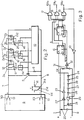
- the possible embodiment of the timing circuit 110 is illustrated in Figure 6 and differs from the solution in Figure 3 by the presence of a specific AND logic 35 which activates a fourth state of the circuit following the transducers.
- the signals of the significant components of the circuit 110 in Figure 6 are illustrated in Figure 9.
- the master control unit 9 energises the timing circuit 110, the latter behaves as the preceding circuit shown in Figure 3 in respect of the sequential activation of the three acceleration transducers 2x-2y-2z, the difference being that after the interval of activation of the last transducer 2z the switch 34 is closed, while all the switches 4x-4y-4z are open, so that the voltage present at the negative pole of the output buffer 5 is determined by the loads 6 and 33.
- the switch 34 By establishing a suitable ratio between these two loads, it is possible to make the voltage present on the negative pole of the buffer 5, at the moment of closing of the switch 34, very different from that in the intermediate states of sequential activation of the three acceleration transducers.
- the voltage read at the terminals of the output buffer during the activation of the three acceleration transducers would be of the order of two volts.
- the ratio between the loads 33 and 6 it is possible to make the voltage read at the terminals of the output buffer 5 in the said final state to be of the order of three volts.
- the master control unit 9 would thus be enabled to recognise the said final state without difficulty and to register the termination of NHA measurement, and could therefore proceed to interrupt the current which had been supplied to the circuit located in the tip of the catheter.
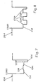
- Figure 7 shows the waveform 1014 which the master control unit 9 perceives during each activation cycle of the timing circuit 110.
- the steps 1114-1214-1314 relate to the activation of the three acceleration transducers, while the final step 1414 relates to the final state of closure of the switch 34.
- the master control unit 9 is aware of the instant of the start of measurement, since it is this unit that determines it; and since, as stated previously, the instant of the end of the enabling cycle of the three acceleration transducers is also known, it can calculate the total time T required to make the measurements on the particular catheter in question and can assign to each transducer a reading time of 1/3 T.
- the master control unit 9 can perform this test operation periodically, at programmed time intervals and in a totally autonomous way in all cases.
- the power consumption of the device does not undergo large variations, since the introduced fourth state lasts only for as long as is necessary for the master control unit to recognise it.
- the final state may be such that it generates a voltage which saturates the current generator disposed in the master control unit 9 and which supplies the device inside the tip of the catheter. In this situation, the power consumption corresponding to the final stable state would be much less than that in the phases of activation of the acceleration transducers.
- Another method of attaining the desired objective consists in providing in the master control unit 9 means which activate the reading of each acceleration transducer by three successive pulses spaced apart by 30 microseconds, which activate inside the tip of the catheter a decoding output counter which acts as a timing circuit and permits the sequential reading of the signals.
- This circuit uses, as switching clock pulses, the activation pulses from the master control unit 9, and the control of data collection is thus totally assigned to the said master control unit, the internal circuitry of the tip 1 of the catheter being used to switch the three transducers sequentially according to the three activation pulses sent in succession from the master control unit 9.
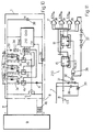
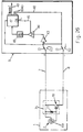
- Figure 10 is a block diagram of a solution of this type which differs from that shown in Figure 5 in the provision of a three-state timing circuit 210 or a four-state circuit 310, as shown in the detail of Figures 11 and 13, both without an internal clock.
- FIG 11 which illustrates the three-state timing circuit 210, without components 33 and 34 shown in Figure 10, differs from that in Figure 6 in the absence of an autonomous clock circuit.
- the other input of the logic circuit 36 is connected to the Schmitt trigger 32 associated with the time constant 31 and the output of the said logic circuit 36 is connected to the reset R of units 15 and 16.
- the clock input CK of unit 15 is then negated to permit switching at the start of each activation pulse, and is connected directly to terminal 8, while the CK input of unit 16 is also negated and is connected to the output Q of the unit 15.
- a diode 39 and a capacitor 38 provide a power supply to enable the counter formed by units 15 and 16 to continue to operate in static conditions even during the 30 microsecond pause between two successive activation pulses belonging to the same train.
- the voltage at the terminals of capacitor 38 decreases during the intervals between two successive pulses of the same train, as a function of the leakage currents of the inversely polarized diode 39 and of the counter in question.
- its static consumption is so limited that the presence of a capacitor 38 of approximately 10 pF, fully compatible with the integration technology used for these circuits, is sufficient.
- the constraint to be imposed on the discharge time of the capacitor 38, with allowance for the total leakage current present in the circuit or any leakage known and introduced a priori, must be such that the counter is kept active in the 30 microsecond pauses between successive activation impulses of a single train and at the same time it must be such as to ensure the switch-off of the circuit disposed in the tip 1 of the catheter, before the arrival of the next pulse train from the master control unit 9, which is at a time distance of approximately 3000 microseconds from the previous one, in order to ensure the resetting of the counter and the correct sequence of the transducers 2x-2y-2z with the first activation pulse of each train.
- Figure 12 shows the waveforms relating to the circuit in Figure 11, where 140-240-340 indicate the train of pulses spaced apart by 30 microseconds, which arrive at intervals of 3000 microseconds from the master control unit 9 to cause the successive switching of the switches 4x-4y-4z.
- the number 41 indicates the variation of the voltage Vc at the terminals of the capacitor 38.
- the time constant 31 is of the order of a microsecond, permitting wide tolerances which do not adversely affect the operation of the instrument, this constant being used exclusively for the resetting of the timing circuit 210.
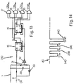
- Figure 13 shows the timing circuit 310 of the four-state circuit shown in Figure 10, including components 33 and 34.
- the circuit shown in figure 13 differs from that in figure 11 in that the output of the logic circuit 35 determines the synchronisation pulse SYNC which controls the fourth state switch 34.
- FIG. 14 shows how, after the final signal 340 of the pulse train 40 which causes the switching of the three acceleration transducers, the fourth state is activated, to provide at the output a signal 440 recognisable in amplitude by the master control unit 9 which will use it as the synchronisation signal to reset the correct transducer activation sequence whenever this is altered by any electrical or other interference.
- Figure 15 shows the possible configuration of the internal part of the master control unit 9 used for the reception and processing of the signal from the three uniaxial transducers disposed in the tip 1, to calculate the modulus or the mean of the peak-to-peak values of NHA read by the three transducers and relating to each cardiac cycle.
- the signals from the three transducers are amplified by a unit 43 and then sampled by means of corresponding sample and hold circuits 44-144-244 which are activated through the clock terminals 45-145-245 in phase with the activation of the said transducers by the unit 47 to which are connected the outputs of the devices 44-144-244 through corresponding band-pass filters 46-146-246 which operate in the band between approximately 15 and 100 Hz.
- the number 48 indicates the output of the unit 47 which sends the pulse train 40 to the tip of the catheter for the sequential activation of the three transducers.
- the signals from the three acceleration transducers, already with an upper band limit of 100 Hz, are reconstructed by an analog method, amplified and filtered in the 15-100 Hz band and collected by the unit 47 which uses analog or digital methods for the measurement of their peak-to-peak value and for subsequent processing in digital form to supply at its output 49 the modulus or the mean of the three peak-to-peak values of NHA measured in the three perpendicular directions by the three acceleration transducers.
- the said peak-to-peak values of the signals from the three acceleration transducers are read at the end of each cycle, and the means which control this reading in the unit 47 are automatically reset after each reading.
- the end of the cycle may be determined by interaction with known means which read a ventricular electrical stimulus or the QRS wave or a defibrillating electric shock, or may be determined autonomously by the said unit 47, after a programmed time interval, of the order of approximately 5 seconds for example.
- Figure 16 shows the signals relating to the device shown in Figure 15.
- the numbers 50-51-52 indicate the signals produced by the three acceleration transducers 2x-2y-2z, while 53 indicates the form of the signal which is cyclically emitted from the tip of the catheter and is sent to the master control unit 9.
- the numbers 54-55-56 indicate the signals emitted from the sample and hold circuits 44-144-244 relating to signals 50-51-52 respectively produced by the acceleration transducers.
- Figures 17 and 18 show the signals detected with the apparatus according to the invention and relating to the modulus of the peak-to-peak values of NHA produced by the three transducers 2x-2y-2z in the resting state and in phases of physical activity respectively.
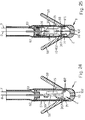
- the disposition of the three acceleration transducers and of the electronic circuit associated with them inside the tip 1 of the catheter is illustrated in Figures 19-20-21.
- the reference number 57 indicates the catheter's sheath of insulating material which has good characteristics of biocompatibility and which terminates in a plurality of tines 58 to fix the tip of the said catheter to the heart tissue.
- the metal stimulating point 59 in the form of a capsule and made of material having good characteristics of biocompatibility, is fixed in the terminal part of the sheath 57 and operates in contact with the heart muscle.
- longitudinal recesses 60 On the inner lateral surface of the point 59 are longitudinal recesses 60 in which are fitted the corner areas of a metal chassis 61 provided with at least one pair of longitudinal walls 161-261 spaced apart by an angle of 90° and with an end wall 361, perpendicular to the preceding walls on which are fixed the three uniaxial acceleration transducers 2x-2y-2z mentioned previously.
- the acceleration transducers are fixed to the walls of the chassis 61 with the interposition between the two parts of an exact thickness 102 of a resilient conducting means, in order to mechanically reduce to approximately 100 Hz the upper limit of the frequency response of the transducers.
- the thickness of the said resilient conducting means may be formed by and coincide with the special transducer fixing adhesives according known techniques described for example in "Mechanical vibration and shock measurements” by Bruel & Kjaer.
- the chassis 61 has a flat terminal part 461 aligned axially in the point 59 and with a forked end pressing on the metal plug 62 which is inserted in the inner end of the point 59 and is axially hollow for the passage of the negative electrode 8.
- the number 63 indicates the seal of ceramic material inserted in the plug 62 to form a grommet.
- the whole of the electronic circuit 64 to be linked with the acceleration transducers, as described previously with reference to the preceding figures, is mounted on the part 461 of the chassis.
- the positive electrode 7 is fixed, for example, to the plug 62 and consequently to all the metal parts housed in the point 59.
- the transducer consists of two small hemispherical bodies 65-165 made of a suitable piezoelectric material, for example of the type shown in the catalogue "N.SG01E-4 transducer” Murata, Piezoelectric ceramics sphere type” and whose metal-coated parts are located on the outer and inner surfaces respectively as indicated by 66-166 and 67-167.
- the inner metal coating 67-167 is connected to a small metal isolated area 367 disposed on the outer face of the said bodies 65-165 and separated electrically from the coating 66-166 by a ring 68 of the material of the bodies 65-165.
- the seismic mass 69 consisting of a metal sphere of suitable diameter is housed in the cavities formed by the hemispherical parts described.
- a small insert of sufficiently rigid anti-wear material for example Parilene or Teflon, may be provided between the surface of the mass 69 and the metal coating 67-167.
- Figures 24 and 25 show that the spherical transducer 2 mentioned previously may be fixed, with the interposition of a layer 102 of resilient material having a thickness and elastic characteristics such that the top of the transducer band is limited to approximately 100 Hz, in a hemispherical socket 70 in the inner cavity of the metal point 59 of the catheter, in which it is retained by a pair of curved pieces 71-171 and by the curved end shape 72 of a small flat metal chassis 73 which terminates with its other forked end 74 pressing on the metal plug 62.
- An appropriate layer of the said material 102 having the function of limiting the top of the transducer band to approximately 100 Hz is also interposed in the area of contact between the transducer and the curved pieces 71-171 and the curved end 72 of the chassis 73.
- the reduction to approximately 100 Hz of the upper limit of the multiaxial transducer may be achieved by any means suitable for the purpose, used in combination with or as an alternative to the means 102 described.
- the multiaxial acceleration transducer whether of the spherical type described above or of the preceding triaxial type, to be surrounded by a fluid or other means of specified viscosity, enabling the aforesaid results to be achieved.
- the negative electrode 8 which passes through the ceramic seal 53 of the plug 52 is connected to the electronic circuit 75 fixed on the chassis 73 and associated with the spherical transducer 2.
- the circuit 75 comprises a buffer made according to conventional methods with a MOS transistor 76 and a coupling resistor 77.
- the circuit 75 will be activated in a pulsed way and the modulus of the NHA measured by it will be transmitted through electrodes 7-8 to the subcutaneously implanted master control unit 9, in which it will be suitably amplified by the device 43, then reconstructed in analog mode by sampling by the sample and hold circuit 44, then filtered by the pass-band filter 46 to eliminate frequencies outside the band of approximately 15-100 Hz, and finally sent to the unit 47 which will supply at its output 49 the modulus or the mean of the peak-to-peak values of NHA measured in each cardiac cycle.
- the output 45 of the unit 47 triggers the clock of the sampling device 44, while the output 48 of the same unit 47 sends to the multiaxial transducer 2, disposed in the tip of the catheter, activation pulses 1040, having a duration of approximately 30 microseconds and sent at intervals of 3000 microseconds, with a consumption equal of course to one third of that of the preceding solution which uses a multiaxial acceleration transducer consisting of three uniaxial acceleration transducers.
- the solution described in the present disclosure namely that of mechanically limiting to 100 Hz the frequency response of the multiaxial acceleration transducer of the composite or simple type, enables the power consumption of the whole instrument to be limited. It should be understood, however, that if the instrument permits higher power consumption, for example in the case of the spherical type of acceleration transducer illustrated in Figures 22 to 26, the acceleration signal may be filtered in the 15-100 Hz band by an electronic method, without previous limitation of the band by the use of dampers 102 or in combination with such limitation.
- the signal generated by the multiaxial acceleration transducer is reconstructed in the master control unit 9 with a suitable sampling frequency, of the order of 1000 Hz for example, and the reconstructed signal is filtered in the 15-100 Hz band by the extraction of the part of the signal representing the cardiac contractility in the isovolumetric phase.
- Any suitable acceleration transducer can be used.
- Known examples include torsional piezoresistive types in which a seismic mass introduces torsional stresses in a piezoresistive element which arrangement is inherently multiaxial; capacitive types in which for three dimensional operation three transducers are combined; and piezoresistive types in which for three dimensional operation three transducers are combined.
- the scope of the invention includes the variant, not illustrated, in which the multiaxial acceleration transducer is fitted near the tip of the catheter, slightly to the rear, for example as in the case of the ring of a bipolar electrode.
- the tip may be made with dimensions and a shape independent of those of the said multiaxial transducer and of the associated electronic circuit.
Landscapes
- Health & Medical Sciences (AREA)
- Life Sciences & Earth Sciences (AREA)
- Engineering & Computer Science (AREA)
- Biomedical Technology (AREA)
- Veterinary Medicine (AREA)
- Public Health (AREA)
- General Health & Medical Sciences (AREA)
- Animal Behavior & Ethology (AREA)
- Heart & Thoracic Surgery (AREA)
- Biophysics (AREA)
- Surgery (AREA)
- Cardiology (AREA)
- Medical Informatics (AREA)
- Molecular Biology (AREA)
- Physics & Mathematics (AREA)
- Pathology (AREA)
- Radiology & Medical Imaging (AREA)
- Nuclear Medicine, Radiotherapy & Molecular Imaging (AREA)
- Bioinformatics & Cheminformatics (AREA)
- Chemical & Material Sciences (AREA)
- Medicinal Chemistry (AREA)
- Hematology (AREA)
- Physiology (AREA)
- Pharmacology & Pharmacy (AREA)
- Computer Networks & Wireless Communication (AREA)
- Electrotherapy Devices (AREA)
- Measuring Pulse, Heart Rate, Blood Pressure Or Blood Flow (AREA)
- Measuring And Recording Apparatus For Diagnosis (AREA)
Claims (29)
- Vorrichtung zur Überwachung der Herzkontraktilität mit einem Katheter mit einer Spitze (1) zum Einsetzen in eine Kammer des Herzmuskels, wobei der Katheter an oder nahe seinem Ende einen auf die natürliche Herzbeschleunigung ansprechenden Beschleunigungswandler (2) enthält, um ein Beschleunigungssignal über den genannten Katheter an eine Signalverarbeitungseinrichtung (9) zu liefern, dadurch gekennzeichnet, daß die Signalverarbeitungseinrichtung und/oder der Beschleunigungswandler zur Unterdrückung der Frequenzen außerhalb des Bereiches von 15 Hz bis 100 Hz eingerichtet ist oder sind.
- Vorrichtung nach Anspruch 1, bei der die Signalverarbeitungseinrichtung für die Bestimmung des Scheitelwerts des Beschleunigungssignals eingerichtet ist.
- Vorrichtung nach Anspruch 1 oder 2, dadurch gekennzeichnet, daß der Beschleunigungswandler in dem Katheter unter Zwischenlage einer Dämpfungseinrichtung (102) angeordnet ist, die die obere Grenze der Ansprechfrequenz des genannten Beschleunigungswandlers auf etwa 100 Hz reduziert.
- Vorrichtung nach Anspruch 3, dadurch gekennzeichnet, daß die Dämpfungseinrichtung (102) ein nachgiebiges leitendes Material aufweist, das zwischen dem Wandler und einem entsprechenden Träger angeordnet ist.
- Vorrichtung nach Anspruch 4, bei der das nachgiebige leitende Material Klebemittel umfaßt, die den Beschleunigungswandler an der entsprechenden Trägerfläche fixieren.
- Vorrichtung nach Anspruch 3, dadurch gekennzeichnet, daß die Dämpfungseinrichtung (102) ein genügend elastisches und weiches Material umfaßt, das den Beschleunigungswandler in dem Katheter umgibt.
- Vorrichtung nach Anspruch 3, dadurch gekennzeichnet, daß die Dämpfungseinrichtung (102) ein Fuid umfaßt, das den Beschleunigungswandler in dem Katheter umgibt.
- Vorrichtung nach einem vorhergehenden Anspruch, dadurch gekennzeichnet, daß der Beschleunigungswandler auf die Beschleunigung in irgendeiner räumlichen Richtung anspricht.
- Vorrichtung nach Anspruch 8, bei der der Beschleunigungswandler drei uniaxiale Beschleunigungswandler umfaßt, die mit der Erfassungsachse, in der sie empfindlich sind, senkrecht zueinander angeordnet sind, und in der die Signalverarbeitungseinrichtung zur Bestimmung des Werts von Spitze zu Spitze des Beschleunigungssignals von jedem uniaxialen Wandler und zur Bestimmung des Moduls oder des Durchschnitts der drei Signalwerte von Spitze zu Spitze eingerichtet ist.
- Vorrichtung nach Anspruch 8, bei der der Beschleunigungswandler ein von dem Modul des Beschleunigungsvektors, dem der Sensor ausgesetzt ist, abhängiges Beschleunigungssignal liefert.
- Vorrichtung nach einem vorhergehenden Anspruch, mit Einrichtungen zur periodischen Abtastung der Ausgangsgröße des Beschleunigungswandlers zwecks Lieferung eines Abtast-Beschleunigungssignals, und bei der die Signalverarbeitungseinrichtung Mittel zur Wiederherstellung eines kontinuierlichen Beschleunigungssignals aus dem Abtast-Beschleunigungssignal umfaßt, und mit einem Bandpassfilter mit einem Durchlassbereich der genannten 15 Hz bis 100 Hz zwecks Filterung des wiederhergestellten Beschleunigungssignals.
- Vorrichtung nach Anspruch 11, gekennzeichnet durch eine auf dem Beschleunigungswandler angeordnete mechanische Dämpfungseinrichtung (102) zur Begrenzung des oberen Bandendes auf etwa 100 Hz.
- Vorrichtung nach Anspruch 12, wenn dieser von Anspruch 8 abhängt, dadurch gekennzeichnet, daß die Signalverarbeitungseinrichtung (9)Mittel zum Aussenden von Stromimpulsen zur Aktivierung des multiaxialen Beschleunigungswandlers (2), wobei die Impulse eine Dauer von etwa 30 Mikrosekunden bei Intervallen von etwa 3000 Mikrosekunden haben, undMittel (47) zur Bestimmung der Werte von Spitze zu Spitze des gefilterten Signals und zu ihrer Verarbeitung zwecks Berechnung des Wertes der Herzkontraktilität in aufeinanderfolgenden Herzzyklen umfaßt.
- Vorrichtung nach Anspruch 13, mit Einrichtungen zur Bestimmung des Endes jedes Herzzyklus, die Mittel zur Feststellung eines elektrischen Ventrikelreizes oder der QRS-Welle oder eines elektrischen Defibrillierungsschocks oder eines programmierten Zeitintervalls in der Größenordnung von etwa 5 Sekunden umfaßt.
- Vorrichtung nach einem der Ansprüche 11 bis 14, bei der der multiaxiale Beschleunigungswandler (2) drei uniaxiale Beschleunigungswandler (2x-2y-2z) umfaßt, die mit ihren Abtastachsen, in denen sie empfindlich sind, senkrecht zueinander angeordnet sind, wobei die Wandler Puffer (11-111-211) haben, die über entsprechende Wandlerschalter (4x-4y-4z) an den Eingang eines Ausgangspuffers (5) angeschlossen sind, der auch eine Versorgungsspannung für eine Taktsteuerschaltung (10) liefert, die die genannten Schalter steuert, so daß die von den drei Beschleunigungswandlern gelieferten Signale in separaten und aufeinanderfolgenden Zeitintervallen verfügbar sind.
- Vorrichtung nach Anspruch 15, bei der eine der Abtastachsen mit der Achse der Katheterspitze (1) ausgefluchtet ist.
- Vorrichtung nach Anspruch 14 oder 15, bei der Einrichtungen vorgesehen sind, um die Taktsteuerungsschaltung (10) zu aktivieren, wenn sie von der Signalverarbeitungseinrichtung (9) einen Impuls (14) in der Größenordnung von einigen zehn Mikroampere empfängt, der für ein Gesamtzeitintervall (T) in der Größenordnung von etwa einhundert Mikrosekunden aufrechterhalten wird.
- Vorrichtung nach einem der Ansprüche 15 bis 17, bei der die Taktsteuerschaltung (10) einen Zähler (15-16) mit Ausgängen (17-18-19) zur Steuerung der Wandlerschalter (4x-4y-4z) umfaßt, der mit Mitteln (32) zum Zurückstellen bei Empfang eines Aktivierungssignals (14) von der Signalverarbeitungseinrichtung (9) versehen ist und der mit Taktgebern (20-21-22-23-24-25-26-27-28-29) zur Erzeugung von Schalttaktimpulsen von etwa 30 Mikrosekunden versehen ist, wobei Mittel (29-30) zur Deaktivierung oder Abschaltung der Taktgeber vorgesehen sind, wenn der Zähler eine vorbestimmte Zahl erreicht.
- Vorrichtung nach einem der Ansprüche 15 bis 18, bei der ein Eingang zu dem Ausgangspuffer (5) auch durch einen Lastschalter (34) an eine Last (33) anschließbar ist, wobei die Taktsteuerschaltung (110) einen Zähler (15-16) mit Ausgängen umfaßt, die die Wandlerschalter und den Lastschalter steuern, so daß bei Betätigung des Lastschalters die Spannung am Ausgang des Ausgangspuffers (5) ein deutliches Lese-Endsignal erzeugt, wobei die Signalverarbeitungseinrichtung (9) auf das Lese-Endsignal anspricht, um die Versorgung der gesamten in dem Katheter befindlichen Schaltung zu unterbrechen.
- Vorrichtung nach Anspruch 19, bei der die bei Betätigung des Lastschalters an dem Ausgangspuffer (5) anliegende Spannung so ist, daß ein Stromgenerator in der Hauptsteueranlage (9), der die in dem Katheter angeordnete Schaltung versorgt, gesättigt ist.
- Vorrichtung nach Anspruch 19, dadurch gekennzeichnet, daß die Taktsteuerschaltung (110) einen Lese-Endzustand mit jedem Aktivierungsunterintervall des Beschleunigungswandlers assoziiert, wobei in der Hauptsteueranlage (9) Einrichtungen vorgesehen sind, damit die Anlage die Leseintervalle der einzelnen Wandler in Echtzeit lesen läßt und sich demgemäß anpasst.
- Vorrichtung nach Anspruch 15 oder 16, dadurch gekennzeichnet, daß die Signalverarbeitungseinrichtung (9) eine Folge der genannten Stromimpulse in zyklischen Intervallen liefert und jeder Impuls der Folge von dem nächsten Impuls getrennt ist, wobei die Taktsteuerschaltung einen Zähler (15-16) zur Zählung der Impulse in der genannten Impulsfolge umfaßt und vier Ausgänge (17-18-19-35) hat, von denen die ersten drei Ausgänge die Schalter der Beschleunigungswandler (2x-2y-2z) steuern, während der vierte Ausgang (35) über eine Verzögerungsleitung (37) und eine logische Schaltung (36) den Zähler zurückstellt, wobei dieser Zustand auch durch eine geeignete Zeitkonstante (31) zu Beginn des genannten Zyklus geschaffen wird und ein Kondensator (38) Energie für die Taktsteuerschaltung liefert, um den Zähler zwischen den Impulsen in der Folge aktiv zu halten, jedoch in einem Zeitintervall entladen wird, das kleiner als das zwischen den Impulsfolgen (40) von der Signalverarbeitungseinrichtung ist.
- Vorrichtung nach Anspruch 19, dadurch gekennzeichnet, daß die Taktsteuerschaltung (310) auf eine Impulsfolge (40) von der Hauptsteueranlage (9) anspricht, um nacheinander die Wandlerschalter (4x-4y-4z) und den Lastschalter (34) anzusteuern, wobei die genannte Impulsfolge alle 3000 Mikrosekunden eine zyklische Wiederholung hat und jeder Impuls der Folge etwa 30 Mikrosekunden dauert und etwa 30 Mikrosekunden von dem nächsten Impuls getrennt ist, und wobei die Taktsteuerschaltung (310) einen Zähler (15-16) und vier Ausgänge (17-18-19-35) zur Steuerung der Wandlerschalter und des Lastschalters in Folge umfaßt, ein Schaltverzug (31) in der Größenordnung einer Mikrosekunden vorgesehen ist, so daß der Zähler zurückgestellt werden kann, und ein Kondensator (38) Energie an den Zähler liefert und so eingerichtet ist, daß er den Zähler wenigstens 30 Mikrosekunden aktiv hält.
- Vorrichtung nach einem der Ansprüche 15 bis 23, dadurch gekennzeichnet, daß die Verarbeitungseinrichtung (9) Einrichtungen (44-144-244) zur Wiederherstellung kontinuierlicher, auf die drei Beschleunigungswandler (2x-2y-2z) bezogener Beschleunigungssignale und Bandpassfilter (46-146-246) zur Filterung der wiederhergestellten Signale in dem Durchlassbereich von etwa 15 bis 100 Hz umfaßt, wobei die so erhaltenen drei Signale durch Einrichtungen (47) verarbeitet werden, die ihren Wert von Spitze zu Spitze bestimmen und dann den Modul oder den Durchschnittswert der drei Werte von Spitze zu Spitze bestimmen.
- Vorrichtung nach Anspruch 13, bei der eine kleine Aufbauplatte (61) in einem hohlen Metallkörper (59) an der Spitze des Katheters befestigt und mit einem Abschnitt mit wenigstens zwei zueiander senkrechten Längswandungen (161-261) versehen ist und eine zu den vorgenannten Wandungen senkrechte Stirnwandung (361) hat, wobei die entsprechenden uniaxialen Beschleunigungswandler an diesen Wandungen unter Zwischenlage eines Dämpfers (102) angebracht sind, der die Obergrenze ihrer Ansprechfrequenz auf etwa 100 Hz begrenzt, wobei die genannte Aufbauplatte einen flachen Endabschnitt (461) hat, der koaxial in dem hohlen Katheterkörper angeordnet ist und ein gegabeltes Ende hat, das auf einen Metallstopfen (62) drückt, der auf der Öffnung des Hohlkörpers befestigt ist und eine isolierte Durchführung (63) hat, durch die die Elektrode (8) hindurchtritt, die mit der an die Beschleunigungswandler angeschlossenen elektronischen Schaltung (64) verbunden und an dem flachen Ende der Aufbauplatte (61) fixiert ist, wobei die andere Elektrode (7) an dem genannten Metallstopfen und/oder irgendeinem anderen geeigneten Punkt befestigt ist.
- Vorrichtung nach Anspruch 10 oder irgendeinem der Ansprüche 11 bis 13, wenn sie von Anspruch 10 abhängig sind, bei der der multiaxiale Wandler (2) einen Körper aus piezoelektrischem Material in Form eines vorzugsweise kugelförmigen Gehäuses hat, das durch zwei halbkugelförmige Körper (65-165) auf der Innen- und Außenseite mit entsprechenden Metallschichten (66-166 und 67-167) gebildet ist, wobei die innere Metallschicht an einen äußeren Kontakt (367) angeschlossen ist, der eine Elektrode des Wandlers bildet, und von der übrigen äußeren Metallschicht, die die andere Elektrode des Wandlers bildet, elektrisch isoliert ist, während innerhalb des Gehäusekörpers eine kugelförmige seismische Masse (69) vorgesehen ist.
- Vorrichtung nach Anspruch 26, bei der zwischen der seismischen Masse (69) und der Inneren Metallschicht (67-167) wenigstens eine Schicht aus verschleißfestem Material vorgesehen ist.
- Vorrichtung nach Anspruch 26 oder 27, bei der der Gehäusekörper des multiaxialen Wandlers (2) in der Endfassung (70) des hohlen Metallkörpers (59) der Katheterspitze untergebracht ist und die isolierte Elektrode (367) des Wandlers auf der der Fassung gegenüberliegenden Seite angeordnet ist und an Ort und Stelle durch das vielfach gegabelte Ende (71-171-72) einer flachen Metallplatte (73) erfaßt und gehalten wird, die in Längsrichtung in dem genannten Körper angeordnet ist und die an den Wandler angeschlossene elektronische Schaltung (75) trägt und die mit ihrem anderen Ende auf den Metallstopfen (62) drückt, der in der Öffnung des Hohlkörpers (59) fixiert ist und durch dessen isolierte Durchführung (63) die an die elektronische Schaltung angeschlossene Elektrode (8) führt, wobei die andere Elektrode (7) mit dem genannten Stopfen und/oder einem anderen geeigneten Punkt verbunden ist.
- Vorrichtung nach einem der Ansprüche 26 bis 28, bei der die an den multiaxialen Beschleunigungswandler (2) mit der kugelförmigen seismischen Masse angeschlossene elektronische Schaltung (75) einen aus einem MOS-Transistor (76) und einem entsprechenden Kupplungswiderstand (77) bestehenden Puffer umfaßt.
Applications Claiming Priority (3)
| Application Number | Priority Date | Filing Date | Title |
|---|---|---|---|
| GB9411397 | 1994-06-07 | ||
| GB9411397A GB9411397D0 (en) | 1994-06-07 | 1994-06-07 | Apparatus for monitoring cardiac contractility |
| PCT/GB1995/001326 WO1995033517A1 (en) | 1994-06-07 | 1995-06-07 | Apparatus for monitoring cardiac contractility |
Publications (2)
| Publication Number | Publication Date |
|---|---|
| EP0764038A1 EP0764038A1 (de) | 1997-03-26 |
| EP0764038B1 true EP0764038B1 (de) | 1998-12-09 |
Family
ID=10756338
Family Applications (1)
| Application Number | Title | Priority Date | Filing Date |
|---|---|---|---|
| EP95921070A Expired - Lifetime EP0764038B1 (de) | 1994-06-07 | 1995-06-07 | Vorrichtung zur messung der kontraktionskraft des herzens |
Country Status (8)
| Country | Link |
|---|---|
| US (1) | US6077236A (de) |
| EP (1) | EP0764038B1 (de) |
| AT (1) | ATE174228T1 (de) |
| AU (1) | AU2626995A (de) |
| DE (1) | DE69506544T2 (de) |
| ES (1) | ES2127533T3 (de) |
| GB (1) | GB9411397D0 (de) |
| WO (1) | WO1995033517A1 (de) |
Families Citing this family (124)
| Publication number | Priority date | Publication date | Assignee | Title |
|---|---|---|---|---|
| US6033366A (en) | 1997-10-14 | 2000-03-07 | Data Sciences International, Inc. | Pressure measurement device |
| US6296615B1 (en) | 1999-03-05 | 2001-10-02 | Data Sciences International, Inc. | Catheter with physiological sensor |
| US6409674B1 (en) | 1998-09-24 | 2002-06-25 | Data Sciences International, Inc. | Implantable sensor with wireless communication |
| DE29909923U1 (de) * | 1999-06-08 | 1999-09-02 | Günther, Rolf W., Prof. Dr.med., 52074 Aachen | Intravasal impantierbare Kapsel mit Halteapparat für ein miniaturisiertes Meßsystem zur telemetrischen Erfassung medizinischer Kenngrößen |
| US6440078B1 (en) * | 1999-07-23 | 2002-08-27 | Roberto Curiel | Method and system of determining cardiac contractility |
| US6939303B2 (en) * | 1999-07-23 | 2005-09-06 | Provecto Tecnico R-2000, Ca | Method and system of determining cardiac contractility |
| US6705999B2 (en) * | 2001-03-30 | 2004-03-16 | Guidant Corporation | Method and apparatus for determining the coronary sinus vein branch accessed by a coronary sinus lead |
| US6937899B2 (en) * | 2001-08-30 | 2005-08-30 | Medtronic, Inc. | Ischemia detection |
| US7181268B2 (en) * | 2001-12-03 | 2007-02-20 | Medtronic, Inc. | Ischemia detection |
| US7127289B2 (en) * | 2001-12-05 | 2006-10-24 | Cardiac Pacemakers, Inc. | Cardiac resynchronization system employing mechanical measurement of cardiac walls |
| US6980866B2 (en) * | 2001-12-05 | 2005-12-27 | Cardiac Pacemakers, Inc. | Apparatus for sensing cardiac contractile function |
| NO20016385L (no) * | 2001-12-27 | 2003-06-30 | Medinnova Sf | System for å overvåke pulsendringer, fortrinnsvis en hjertemuskel |
| US6855115B2 (en) | 2002-01-22 | 2005-02-15 | Cardiomems, Inc. | Implantable wireless sensor for pressure measurement within the heart |
| US7147604B1 (en) | 2002-08-07 | 2006-12-12 | Cardiomems, Inc. | High Q factor sensor |
| US7325453B2 (en) * | 2002-12-10 | 2008-02-05 | Koninklijke Philips Electronics, N.V. | Activity monitoring |
| US7845228B2 (en) * | 2002-12-10 | 2010-12-07 | Koninklijke Philips Electronics N.V. | Activity monitoring |
| EP1571989A1 (de) * | 2002-12-10 | 2005-09-14 | Koninklijke Philips Electronics N.V. | Aktivitätsüberwachung |
| US6885889B2 (en) | 2003-02-28 | 2005-04-26 | Medtronic, Inc. | Method and apparatus for optimizing cardiac resynchronization therapy based on left ventricular acceleration |
| US7130681B2 (en) | 2003-05-09 | 2006-10-31 | Medtronic, Inc. | Use of accelerometer signal to augment ventricular arrhythmia detection |
| US7003348B1 (en) | 2003-07-01 | 2006-02-21 | Pacesetter, Inc. | Monitoring cardiac geometry for diagnostics and therapy |
| US7613513B1 (en) | 2003-07-01 | 2009-11-03 | Pacesetter, Inc. | System and method for determining cardiac geometry |
| US7092759B2 (en) | 2003-07-30 | 2006-08-15 | Medtronic, Inc. | Method of optimizing cardiac resynchronization therapy using sensor signals of septal wall motion |
| US8026729B2 (en) | 2003-09-16 | 2011-09-27 | Cardiomems, Inc. | System and apparatus for in-vivo assessment of relative position of an implant |
| AU2004274005A1 (en) | 2003-09-16 | 2005-03-31 | Cardiomems, Inc. | Implantable wireless sensor |
| US7245117B1 (en) | 2004-11-01 | 2007-07-17 | Cardiomems, Inc. | Communicating with implanted wireless sensor |
| US7142919B2 (en) * | 2003-10-24 | 2006-11-28 | Medtronic, Inc. | Reconfigurable, fault tolerant multiple-electrode cardiac lead systems |
| US20050172311A1 (en) * | 2004-01-31 | 2005-08-04 | Nokia Corporation | Terminal and associated method and computer program product for monitoring at least one activity of a user |
| US7203541B2 (en) * | 2004-03-12 | 2007-04-10 | Medtronic, Inc. | Real-time optimization of right to left ventricular timing sequence in bi-ventricular pacing of heart failure patients |
| US7640046B2 (en) * | 2004-06-18 | 2009-12-29 | Cardiac Pacemakers, Inc. | Methods and apparatuses for localizing myocardial infarction during catheterization |
| US7272434B2 (en) * | 2004-08-13 | 2007-09-18 | Boston Scientific Scimed, Inc. | Automatic post-pacing interval measurement |
| US20060167529A1 (en) | 2005-01-26 | 2006-07-27 | Schecter Stuart O | Method and algorithm for defining the pathologic state from a plurality of intrinsically and extrinsically derived signals |
| US20100312129A1 (en) | 2005-01-26 | 2010-12-09 | Schecter Stuart O | Cardiovascular haptic handle system |
| US20090030332A1 (en) * | 2005-01-26 | 2009-01-29 | Schecter Stuart O | microfabricated cardiac sensor with tactile feedback and method and apparatus for calibrating the same using a plurality of signals |
| US20060178586A1 (en) * | 2005-02-07 | 2006-08-10 | Dobak John D Iii | Devices and methods for accelerometer-based characterization of cardiac function and identification of LV target pacing zones |
| US20080021336A1 (en) | 2006-04-24 | 2008-01-24 | Dobak John D Iii | Devices and methods for accelerometer-based characterization of cardiac synchrony and dyssynchrony |
| US20060271121A1 (en) | 2005-05-25 | 2006-11-30 | Cardiac Pacemakers, Inc. | Closed loop impedance-based cardiac resynchronization therapy systems, devices, and methods |
| AU2006262287A1 (en) | 2005-06-21 | 2007-01-04 | Cardiomems, Inc. | Method of manufacturing implantable wireless sensor for in vivo pressure measurement |
| US7621036B2 (en) | 2005-06-21 | 2009-11-24 | Cardiomems, Inc. | Method of manufacturing implantable wireless sensor for in vivo pressure measurement |
| US9839781B2 (en) | 2005-08-22 | 2017-12-12 | Cardiac Pacemakers, Inc. | Intracardiac impedance and its applications |
| US7869876B2 (en) | 2005-10-07 | 2011-01-11 | Medtronic, Inc. | Method and apparatus for monitoring and optimizing atrial function |
| EP1993436B1 (de) | 2006-03-14 | 2014-06-11 | CardioMems, Inc. | Kommunikation mit einem implantierten drahtlosen sensor |
| US8738131B2 (en) * | 2007-03-20 | 2014-05-27 | Medtronic, Inc. | Mechanical ventricular pacing capture detection for a post extrasystolic potentiation (PESP) pacing therapy using at least one lead-based accelerometer |
| US8282568B2 (en) | 2007-04-30 | 2012-10-09 | Bio-Medisinsk Innovasjon As | Method for estimating cardiac pumping capacity |
| US7787942B2 (en) | 2007-04-30 | 2010-08-31 | Medtronic, Inc. | Mechanical ventricular pacing non-capture detection for a refractory period stimulation (RPS) pacing therapy using at least one lead-based accelerometer |
| EP2429391A2 (de) * | 2009-04-22 | 2012-03-21 | Cardiac Pacemakers, Inc. | Messungen der veränderlichkeit der kardialen kontraktilität bei ischämie |
| US8942828B1 (en) | 2011-04-13 | 2015-01-27 | Stuart Schecter, LLC | Minimally invasive cardiovascular support system with true haptic coupling |
| US10013082B2 (en) | 2012-06-05 | 2018-07-03 | Stuart Schecter, LLC | Operating system with haptic interface for minimally invasive, hand-held surgical instrument |
| CN107206242B (zh) | 2015-02-06 | 2020-10-30 | 心脏起搏器股份公司 | 用于电刺激治疗的安全递送的系统和方法 |
| US10046167B2 (en) | 2015-02-09 | 2018-08-14 | Cardiac Pacemakers, Inc. | Implantable medical device with radiopaque ID tag |
| EP3265172B1 (de) | 2015-03-04 | 2018-12-19 | Cardiac Pacemakers, Inc. | System zur behandlung von herzrhythmusstörungen |
| CN108136186B (zh) | 2015-08-20 | 2021-09-17 | 心脏起搏器股份公司 | 用于医疗装置之间的通信的系统和方法 |
| EP3337559B1 (de) | 2015-08-20 | 2019-10-16 | Cardiac Pacemakers, Inc. | Systeme und verfahren zur kommunikation zwischen medizinischen vorrichtungen |
| CN108136189B (zh) | 2015-08-28 | 2021-10-15 | 心脏起搏器股份公司 | 用于行为响应信号检测和治疗递送的系统 |
| WO2017040115A1 (en) | 2015-08-28 | 2017-03-09 | Cardiac Pacemakers, Inc. | System for detecting tamponade |
| US10226631B2 (en) | 2015-08-28 | 2019-03-12 | Cardiac Pacemakers, Inc. | Systems and methods for infarct detection |
| US10092760B2 (en) | 2015-09-11 | 2018-10-09 | Cardiac Pacemakers, Inc. | Arrhythmia detection and confirmation |
| EP3359251B1 (de) | 2015-10-08 | 2019-08-07 | Cardiac Pacemakers, Inc. | Anpassung der stimulationsrate bei einer implantierbaren medizinischen vorrichtung |
| US10183170B2 (en) | 2015-12-17 | 2019-01-22 | Cardiac Pacemakers, Inc. | Conducted communication in a medical device system |
| US10905886B2 (en) | 2015-12-28 | 2021-02-02 | Cardiac Pacemakers, Inc. | Implantable medical device for deployment across the atrioventricular septum |
| US10583303B2 (en) | 2016-01-19 | 2020-03-10 | Cardiac Pacemakers, Inc. | Devices and methods for wirelessly recharging a rechargeable battery of an implantable medical device |
| EP3411113B1 (de) | 2016-02-04 | 2019-11-27 | Cardiac Pacemakers, Inc. | Einführungssystem mit kraftsensor für drahtlose kardiale vorrichtung |
| EP3436142B1 (de) | 2016-03-31 | 2025-04-30 | Cardiac Pacemakers, Inc. | Implantierbare medizinische vorrichtung mit wiederaufladbarer batterie |
| US10328272B2 (en) | 2016-05-10 | 2019-06-25 | Cardiac Pacemakers, Inc. | Retrievability for implantable medical devices |
| US10668294B2 (en) | 2016-05-10 | 2020-06-02 | Cardiac Pacemakers, Inc. | Leadless cardiac pacemaker configured for over the wire delivery |
| EP3474945B1 (de) | 2016-06-27 | 2022-12-28 | Cardiac Pacemakers, Inc. | Herztherapiesystem unter verwendung von subkutan gemessenen p-wellen zur resynchronisation der stimulationsverwaltung |
| US11207527B2 (en) | 2016-07-06 | 2021-12-28 | Cardiac Pacemakers, Inc. | Method and system for determining an atrial contraction timing fiducial in a leadless cardiac pacemaker system |
| WO2018009392A1 (en) | 2016-07-07 | 2018-01-11 | Cardiac Pacemakers, Inc. | Leadless pacemaker using pressure measurements for pacing capture verification |
| EP3487579B1 (de) | 2016-07-20 | 2020-11-25 | Cardiac Pacemakers, Inc. | System zur verwendung eines vorhofkontraktionszeitmarkers bei einem elektrodenlosen herzschrittmachersystem |
| EP3500342B1 (de) | 2016-08-19 | 2020-05-13 | Cardiac Pacemakers, Inc. | Transseptale implantierbare medizinische vorrichtung |
| EP3503799B1 (de) | 2016-08-24 | 2021-06-30 | Cardiac Pacemakers, Inc. | Integrierte herzresynchronisationstherapie mit mehreren vorrichtungen unter verwendung der zeit von p-welle bis schritt |
| EP3503970B1 (de) | 2016-08-24 | 2023-01-04 | Cardiac Pacemakers, Inc. | Kardiale resynchronisierung mittels fusionsförderung zur taktungsverwaltung |
| US10758737B2 (en) | 2016-09-21 | 2020-09-01 | Cardiac Pacemakers, Inc. | Using sensor data from an intracardially implanted medical device to influence operation of an extracardially implantable cardioverter |
| US10994145B2 (en) | 2016-09-21 | 2021-05-04 | Cardiac Pacemakers, Inc. | Implantable cardiac monitor |
| US10905889B2 (en) | 2016-09-21 | 2021-02-02 | Cardiac Pacemakers, Inc. | Leadless stimulation device with a housing that houses internal components of the leadless stimulation device and functions as the battery case and a terminal of an internal battery |
| US10765871B2 (en) | 2016-10-27 | 2020-09-08 | Cardiac Pacemakers, Inc. | Implantable medical device with pressure sensor |
| US10758724B2 (en) | 2016-10-27 | 2020-09-01 | Cardiac Pacemakers, Inc. | Implantable medical device delivery system with integrated sensor |
| EP3532160B1 (de) | 2016-10-27 | 2023-01-25 | Cardiac Pacemakers, Inc. | Separate vorrichtung bei der verwaltung der schrittpulsenergie eines herzschrittmachers |
| US10413733B2 (en) | 2016-10-27 | 2019-09-17 | Cardiac Pacemakers, Inc. | Implantable medical device with gyroscope |
| WO2018081275A1 (en) | 2016-10-27 | 2018-05-03 | Cardiac Pacemakers, Inc. | Multi-device cardiac resynchronization therapy with timing enhancements |
| WO2018081133A1 (en) | 2016-10-27 | 2018-05-03 | Cardiac Pacemakers, Inc. | Implantable medical device having a sense channel with performance adjustment |
| US10617874B2 (en) | 2016-10-31 | 2020-04-14 | Cardiac Pacemakers, Inc. | Systems and methods for activity level pacing |
| CN109952128B (zh) | 2016-10-31 | 2023-06-13 | 心脏起搏器股份公司 | 用于活动水平起搏的系统 |
| US10583301B2 (en) | 2016-11-08 | 2020-03-10 | Cardiac Pacemakers, Inc. | Implantable medical device for atrial deployment |
| WO2018089308A1 (en) | 2016-11-09 | 2018-05-17 | Cardiac Pacemakers, Inc. | Systems, devices, and methods for setting cardiac pacing pulse parameters for a cardiac pacing device |
| US10639486B2 (en) | 2016-11-21 | 2020-05-05 | Cardiac Pacemakers, Inc. | Implantable medical device with recharge coil |
| WO2018093605A1 (en) | 2016-11-21 | 2018-05-24 | Cardiac Pacemakers, Inc. | Leadless cardiac pacemaker providing cardiac resynchronization therapy |
| EP3541473B1 (de) | 2016-11-21 | 2020-11-11 | Cardiac Pacemakers, Inc. | Elektrodenloser herzschrittmacher mit multimodaler kommunikation |
| US10881869B2 (en) | 2016-11-21 | 2021-01-05 | Cardiac Pacemakers, Inc. | Wireless re-charge of an implantable medical device |
| WO2018094342A1 (en) | 2016-11-21 | 2018-05-24 | Cardiac Pacemakers, Inc | Implantable medical device with a magnetically permeable housing and an inductive coil disposed about the housing |
| US11207532B2 (en) | 2017-01-04 | 2021-12-28 | Cardiac Pacemakers, Inc. | Dynamic sensing updates using postural input in a multiple device cardiac rhythm management system |
| EP3573709A1 (de) | 2017-01-26 | 2019-12-04 | Cardiac Pacemakers, Inc. | Elektrodenlose vorrichtung mit umspritzten bauteilen |
| EP3573706B1 (de) | 2017-01-26 | 2025-08-27 | Cardiac Pacemakers, Inc. | Intrakörpervorrichtungskommunikation mit redundanter nachrichtenübertragung |
| US10737102B2 (en) | 2017-01-26 | 2020-08-11 | Cardiac Pacemakers, Inc. | Leadless implantable device with detachable fixation |
| EP3576615B1 (de) | 2017-02-06 | 2024-08-21 | Western Sydney Local Health District | Vorrichtung zur überwachung von herzdysfunktion |
| US10905872B2 (en) | 2017-04-03 | 2021-02-02 | Cardiac Pacemakers, Inc. | Implantable medical device with a movable electrode biased toward an extended position |
| JP6953614B2 (ja) | 2017-04-03 | 2021-10-27 | カーディアック ペースメイカーズ, インコーポレイテッド | 感知された心拍数に基づくペーシングパルスエネルギー調整を用いた心臓ペースメーカ |
| US10918875B2 (en) | 2017-08-18 | 2021-02-16 | Cardiac Pacemakers, Inc. | Implantable medical device with a flux concentrator and a receiving coil disposed about the flux concentrator |
| US11065459B2 (en) | 2017-08-18 | 2021-07-20 | Cardiac Pacemakers, Inc. | Implantable medical device with pressure sensor |
| EP3684465B1 (de) | 2017-09-20 | 2021-07-14 | Cardiac Pacemakers, Inc. | Implantierbare medizinische vorrichtung mit mehreren betriebsmodi |
| US11185703B2 (en) | 2017-11-07 | 2021-11-30 | Cardiac Pacemakers, Inc. | Leadless cardiac pacemaker for bundle of his pacing |
| EP3717064B1 (de) | 2017-12-01 | 2023-06-07 | Cardiac Pacemakers, Inc. | Verfahren und systeme zur erfassung von atrialen kontraktionstaktmarkern während einer ventrikelfüllung aus einem ventrikulär implantierten leitungslosen herzschrittmacher |
| EP3717060B1 (de) | 2017-12-01 | 2022-10-05 | Cardiac Pacemakers, Inc. | Leitungsloser herzschritzmascher mit reversionärem verhalten |
| CN111432874A (zh) | 2017-12-01 | 2020-07-17 | 心脏起搏器股份公司 | 从心室植入的无引线心脏起搏器检测搜索窗口内心房收缩定时基准的方法和系统 |
| EP3717063B1 (de) | 2017-12-01 | 2023-12-27 | Cardiac Pacemakers, Inc. | Systeme zum erkennen von vorhofkontraktions-timing-bezugswerte und zum bestimmen eines herzintervalls von einem ventrikulär implantierten leitungslosen herzschrittmacher |
| WO2019136148A1 (en) | 2018-01-04 | 2019-07-11 | Cardiac Pacemakers, Inc. | Dual chamber pacing without beat-to-beat communication |
| US11529523B2 (en) | 2018-01-04 | 2022-12-20 | Cardiac Pacemakers, Inc. | Handheld bridge device for providing a communication bridge between an implanted medical device and a smartphone |
| US11235159B2 (en) | 2018-03-23 | 2022-02-01 | Medtronic, Inc. | VFA cardiac resynchronization therapy |
| JP2021518208A (ja) | 2018-03-23 | 2021-08-02 | メドトロニック,インコーポレイテッド | AV同期VfA心臓治療 |
| CN111936046B (zh) | 2018-03-23 | 2024-06-28 | 美敦力公司 | 用于心动过速的vfa心脏治疗 |
| WO2020065582A1 (en) | 2018-09-26 | 2020-04-02 | Medtronic, Inc. | Capture in ventricle-from-atrium cardiac therapy |
| US11207526B2 (en) | 2018-11-14 | 2021-12-28 | Medtronic, Inc. | Methods and apparatus for reducing current drain in a medical device |
| US11951313B2 (en) | 2018-11-17 | 2024-04-09 | Medtronic, Inc. | VFA delivery systems and methods |
| EP3897816B1 (de) | 2018-12-21 | 2024-03-27 | Medtronic, Inc. | Freisetzungssysteme für linksventrikuläre stimulation |
| US11679265B2 (en) | 2019-02-14 | 2023-06-20 | Medtronic, Inc. | Lead-in-lead systems and methods for cardiac therapy |
| US11697025B2 (en) | 2019-03-29 | 2023-07-11 | Medtronic, Inc. | Cardiac conduction system capture |
| US11213676B2 (en) | 2019-04-01 | 2022-01-04 | Medtronic, Inc. | Delivery systems for VfA cardiac therapy |
| US11712188B2 (en) | 2019-05-07 | 2023-08-01 | Medtronic, Inc. | Posterior left bundle branch engagement |
| US11305127B2 (en) | 2019-08-26 | 2022-04-19 | Medtronic Inc. | VfA delivery and implant region detection |
| US11813466B2 (en) | 2020-01-27 | 2023-11-14 | Medtronic, Inc. | Atrioventricular nodal stimulation |
| US12543992B2 (en) | 2020-03-30 | 2026-02-10 | Medtronic, Inc. | Pacing efficacy determination using a representative morphology of external cardiac signals |
| US11911168B2 (en) | 2020-04-03 | 2024-02-27 | Medtronic, Inc. | Cardiac conduction system therapy benefit determination |
| US12465770B2 (en) | 2020-07-31 | 2025-11-11 | Medtronic, Inc. | Coronary sinus conduction system pacing and delivery |
| US11813464B2 (en) | 2020-07-31 | 2023-11-14 | Medtronic, Inc. | Cardiac conduction system evaluation |
| WO2025116916A1 (en) * | 2023-11-30 | 2025-06-05 | Shockwave Medical, Inc. | Shock wave catheter with shock absorber |
Family Cites Families (8)
| Publication number | Priority date | Publication date | Assignee | Title |
|---|---|---|---|---|
| FR2224752B1 (de) * | 1973-04-09 | 1977-09-02 | Thomson Medical Telco | |
| JPS63502398A (ja) * | 1985-10-07 | 1988-09-14 | ト−マス ジエフア−ソン ユニバ−シテイ− | 改良されたペ−スメ−カ装置及び検出された心筋の収縮性に応答する心搏の制御方法 |
| US5109842A (en) * | 1990-09-24 | 1992-05-05 | Siemens Pacesetter, Inc. | Implantable tachyarrhythmia control system having a patch electrode with an integrated cardiac activity system |
| IT1245814B (it) * | 1991-05-21 | 1994-10-18 | Sorin Biomedica Spa | Dispositivo cardiostimolatore del tipo rate responsive |
| FR2685642B1 (fr) * | 1991-12-31 | 1996-09-13 | Ela Medical Sa | Stimulateur cardiaque a frequence asservie a l'effort du patient. |
| US5425750A (en) * | 1993-07-14 | 1995-06-20 | Pacesetter, Inc. | Accelerometer-based multi-axis physical activity sensor for a rate-responsive pacemaker and method of fabrication |
| IT1260692B (it) * | 1993-10-05 | 1996-04-22 | Sorin Biomedica Spa | Dispositivo per la determinazione della funzione miocardica e relativoprocedimento. |
| US5480412A (en) * | 1993-11-16 | 1996-01-02 | Pacesetter, Inc. | System and method for deriving hemodynamic signals from a cardiac wall motion sensor |
-
1994
- 1994-06-07 GB GB9411397A patent/GB9411397D0/en active Pending
- 1994-06-07 US US08/750,842 patent/US6077236A/en not_active Expired - Fee Related
-
1995
- 1995-06-07 ES ES95921070T patent/ES2127533T3/es not_active Expired - Lifetime
- 1995-06-07 WO PCT/GB1995/001326 patent/WO1995033517A1/en not_active Ceased
- 1995-06-07 AT AT95921070T patent/ATE174228T1/de not_active IP Right Cessation
- 1995-06-07 DE DE69506544T patent/DE69506544T2/de not_active Expired - Fee Related
- 1995-06-07 EP EP95921070A patent/EP0764038B1/de not_active Expired - Lifetime
- 1995-06-07 AU AU26269/95A patent/AU2626995A/en not_active Abandoned
Also Published As
| Publication number | Publication date |
|---|---|
| US6077236A (en) | 2000-06-20 |
| DE69506544D1 (de) | 1999-01-21 |
| ATE174228T1 (de) | 1998-12-15 |
| EP0764038A1 (de) | 1997-03-26 |
| DE69506544T2 (de) | 1999-06-17 |
| ES2127533T3 (es) | 1999-04-16 |
| AU2626995A (en) | 1996-01-04 |
| WO1995033517A1 (en) | 1995-12-14 |
| GB9411397D0 (en) | 1994-07-27 |
Similar Documents
| Publication | Publication Date | Title |
|---|---|---|
| EP0764038B1 (de) | Vorrichtung zur messung der kontraktionskraft des herzens | |
| US5304208A (en) | Cardiostimulator device of the rate-responsive type | |
| EP0249820B2 (de) | Herzschrittmacher zur Stimulierung des menschlichen Herzens | |
| US5899927A (en) | Detection of pressure waves transmitted through catheter/lead body | |
| EP1660178B1 (de) | Optimierung der kardialen resynchronisationstherapie mit sensorsignalen der septumwandbewegung | |
| US5702427A (en) | Verification of capture using pressure waves transmitted through a pacing lead | |
| US5782884A (en) | Rate responsive cardiac pacemaker with peak impedance detection for rate control | |
| US8738131B2 (en) | Mechanical ventricular pacing capture detection for a post extrasystolic potentiation (PESP) pacing therapy using at least one lead-based accelerometer | |
| US7787942B2 (en) | Mechanical ventricular pacing non-capture detection for a refractory period stimulation (RPS) pacing therapy using at least one lead-based accelerometer | |
| EP0824935A2 (de) | Elektrode zur Gewebestimulation | |
| EP1561489A2 (de) | Transvalvuläre Impedanzmessung | |
| US20040158294A1 (en) | Self-powered implantable element | |
| EP0080347A1 (de) | Implantierbares dynamisches Druckumwandler-System | |
| US20080269816A1 (en) | Method and Apparatus to Deliver Mechanically Fused Pacing Therapy | |
| JPH0647023B2 (ja) | 心臓ペ−スメ−カ− | |
| US7223237B2 (en) | Implantable biosensor and methods for monitoring cardiac health | |
| EP1758643B1 (de) | Nachweis und/oder überwachung von diastolischer herzinsuffizienz | |
| US5228437A (en) | Cardiac pacemaker and method for detecting cardiac signals | |
| US4419996A (en) | Cardiac pacer apparatus | |
| OHM | Inhibition/Filter Characteristics and Input Impedances of QRS‐Inhibited Demand Pacemakers Determined by in vitro Studies |
Legal Events
| Date | Code | Title | Description |
|---|---|---|---|
| PUAI | Public reference made under article 153(3) epc to a published international application that has entered the european phase |
Free format text: ORIGINAL CODE: 0009012 |
|
| 17P | Request for examination filed |
Effective date: 19970103 |
|
| AK | Designated contracting states |
Kind code of ref document: A1 Designated state(s): AT BE CH DE DK ES FR GB GR IE IT LI LU MC NL PT SE |
|
| 17Q | First examination report despatched |
Effective date: 19970804 |
|
| GRAG | Despatch of communication of intention to grant |
Free format text: ORIGINAL CODE: EPIDOS AGRA |
|
| GRAG | Despatch of communication of intention to grant |
Free format text: ORIGINAL CODE: EPIDOS AGRA |
|
| GRAH | Despatch of communication of intention to grant a patent |
Free format text: ORIGINAL CODE: EPIDOS IGRA |
|
| GRAH | Despatch of communication of intention to grant a patent |
Free format text: ORIGINAL CODE: EPIDOS IGRA |
|
| GRAA | (expected) grant |
Free format text: ORIGINAL CODE: 0009210 |
|
| AK | Designated contracting states |
Kind code of ref document: B1 Designated state(s): AT BE CH DE DK ES FR GB GR IE IT LI LU MC NL PT SE |
|
| PG25 | Lapsed in a contracting state [announced via postgrant information from national office to epo] |
Ref country code: NL Free format text: LAPSE BECAUSE OF FAILURE TO SUBMIT A TRANSLATION OF THE DESCRIPTION OR TO PAY THE FEE WITHIN THE PRESCRIBED TIME-LIMIT Effective date: 19981209 Ref country code: GR Free format text: LAPSE BECAUSE OF NON-PAYMENT OF DUE FEES Effective date: 19981209 Ref country code: BE Free format text: LAPSE BECAUSE OF FAILURE TO SUBMIT A TRANSLATION OF THE DESCRIPTION OR TO PAY THE FEE WITHIN THE PRESCRIBED TIME-LIMIT Effective date: 19981209 Ref country code: AT Free format text: LAPSE BECAUSE OF FAILURE TO SUBMIT A TRANSLATION OF THE DESCRIPTION OR TO PAY THE FEE WITHIN THE PRESCRIBED TIME-LIMIT Effective date: 19981209 |
|
| REF | Corresponds to: |
Ref document number: 174228 Country of ref document: AT Date of ref document: 19981215 Kind code of ref document: T |
|
| REG | Reference to a national code |
Ref country code: CH Ref legal event code: NV Representative=s name: WILLIAM BLANC & CIE CONSEILS EN PROPRIETE INDUSTRI Ref country code: CH Ref legal event code: EP |
|
| ET | Fr: translation filed | ||
| REF | Corresponds to: |
Ref document number: 69506544 Country of ref document: DE Date of ref document: 19990121 |
|
| REG | Reference to a national code |
Ref country code: IE Ref legal event code: FG4D |
|
| ITF | It: translation for a ep patent filed | ||
| PG25 | Lapsed in a contracting state [announced via postgrant information from national office to epo] |
Ref country code: SE Free format text: LAPSE BECAUSE OF FAILURE TO SUBMIT A TRANSLATION OF THE DESCRIPTION OR TO PAY THE FEE WITHIN THE PRESCRIBED TIME-LIMIT Effective date: 19990309 Ref country code: PT Free format text: LAPSE BECAUSE OF FAILURE TO SUBMIT A TRANSLATION OF THE DESCRIPTION OR TO PAY THE FEE WITHIN THE PRESCRIBED TIME-LIMIT Effective date: 19990309 Ref country code: DK Free format text: LAPSE BECAUSE OF FAILURE TO SUBMIT A TRANSLATION OF THE DESCRIPTION OR TO PAY THE FEE WITHIN THE PRESCRIBED TIME-LIMIT Effective date: 19990309 |
|
| REG | Reference to a national code |
Ref country code: ES Ref legal event code: FG2A Ref document number: 2127533 Country of ref document: ES Kind code of ref document: T3 |
|
| NLV1 | Nl: lapsed or annulled due to failure to fulfill the requirements of art. 29p and 29m of the patents act | ||
| PG25 | Lapsed in a contracting state [announced via postgrant information from national office to epo] |
Ref country code: LU Free format text: LAPSE BECAUSE OF NON-PAYMENT OF DUE FEES Effective date: 19990607 Ref country code: IE Free format text: LAPSE BECAUSE OF NON-PAYMENT OF DUE FEES Effective date: 19990607 |
|
| PLBE | No opposition filed within time limit |
Free format text: ORIGINAL CODE: 0009261 |
|
| STAA | Information on the status of an ep patent application or granted ep patent |
Free format text: STATUS: NO OPPOSITION FILED WITHIN TIME LIMIT |
|
| 26N | No opposition filed | ||
| PG25 | Lapsed in a contracting state [announced via postgrant information from national office to epo] |
Ref country code: MC Free format text: LAPSE BECAUSE OF NON-PAYMENT OF DUE FEES Effective date: 19991231 |
|
| REG | Reference to a national code |
Ref country code: IE Ref legal event code: MM4A |
|
| REG | Reference to a national code |
Ref country code: GB Ref legal event code: IF02 |
|
| PGFP | Annual fee paid to national office [announced via postgrant information from national office to epo] |
Ref country code: FR Payment date: 20020529 Year of fee payment: 8 Ref country code: ES Payment date: 20020529 Year of fee payment: 8 |
|
| PGFP | Annual fee paid to national office [announced via postgrant information from national office to epo] |
Ref country code: CH Payment date: 20021127 Year of fee payment: 8 |
|
| PG25 | Lapsed in a contracting state [announced via postgrant information from national office to epo] |
Ref country code: ES Free format text: LAPSE BECAUSE OF NON-PAYMENT OF DUE FEES Effective date: 20030609 |
|
| PG25 | Lapsed in a contracting state [announced via postgrant information from national office to epo] |
Ref country code: LI Free format text: LAPSE BECAUSE OF NON-PAYMENT OF DUE FEES Effective date: 20030630 Ref country code: CH Free format text: LAPSE BECAUSE OF NON-PAYMENT OF DUE FEES Effective date: 20030630 |
|
| REG | Reference to a national code |
Ref country code: CH Ref legal event code: PL |
|
| PG25 | Lapsed in a contracting state [announced via postgrant information from national office to epo] |
Ref country code: FR Free format text: LAPSE BECAUSE OF NON-PAYMENT OF DUE FEES Effective date: 20040227 |
|
| REG | Reference to a national code |
Ref country code: FR Ref legal event code: ST |
|
| PGFP | Annual fee paid to national office [announced via postgrant information from national office to epo] |
Ref country code: GB Payment date: 20040601 Year of fee payment: 10 |
|
| PGFP | Annual fee paid to national office [announced via postgrant information from national office to epo] |
Ref country code: DE Payment date: 20040626 Year of fee payment: 10 |
|
| REG | Reference to a national code |
Ref country code: ES Ref legal event code: FD2A Effective date: 20030609 |
|
| PG25 | Lapsed in a contracting state [announced via postgrant information from national office to epo] |
Ref country code: IT Free format text: LAPSE BECAUSE OF NON-PAYMENT OF DUE FEES Effective date: 20050607 Ref country code: GB Free format text: LAPSE BECAUSE OF NON-PAYMENT OF DUE FEES Effective date: 20050607 |
|
| PG25 | Lapsed in a contracting state [announced via postgrant information from national office to epo] |
Ref country code: DE Free format text: LAPSE BECAUSE OF NON-PAYMENT OF DUE FEES Effective date: 20060103 |
|
| GBPC | Gb: european patent ceased through non-payment of renewal fee |
Effective date: 20050607 |