EP0762846B1 - Systeme permettant de mesurer les reactions d'un oeil au niveau pupillaire - Google Patents
Systeme permettant de mesurer les reactions d'un oeil au niveau pupillaire Download PDFInfo
- Publication number
- EP0762846B1 EP0762846B1 EP95920746A EP95920746A EP0762846B1 EP 0762846 B1 EP0762846 B1 EP 0762846B1 EP 95920746 A EP95920746 A EP 95920746A EP 95920746 A EP95920746 A EP 95920746A EP 0762846 B1 EP0762846 B1 EP 0762846B1
- Authority
- EP
- European Patent Office
- Prior art keywords
- eye
- infrared
- instrument according
- infrared light
- mirror
- Prior art date
- Legal status (The legal status is an assumption and is not a legal conclusion. Google has not performed a legal analysis and makes no representation as to the accuracy of the status listed.)
- Expired - Lifetime
Links
- 238000006243 chemical reaction Methods 0.000 title claims description 12
- 210000001747 pupil Anatomy 0.000 claims description 40
- 238000005259 measurement Methods 0.000 claims description 22
- 238000005286 illumination Methods 0.000 claims description 11
- 230000003287 optical effect Effects 0.000 claims description 10
- 238000000034 method Methods 0.000 claims description 4
- 230000008569 process Effects 0.000 claims description 2
- 230000001105 regulatory effect Effects 0.000 claims 1
- 230000011514 reflex Effects 0.000 description 8
- 230000008859 change Effects 0.000 description 4
- 230000000007 visual effect Effects 0.000 description 4
- 238000013461 design Methods 0.000 description 3
- 230000005855 radiation Effects 0.000 description 3
- 238000012360 testing method Methods 0.000 description 3
- 230000008901 benefit Effects 0.000 description 2
- 230000004397 blinking Effects 0.000 description 2
- 238000011156 evaluation Methods 0.000 description 2
- 230000004424 eye movement Effects 0.000 description 2
- 238000005375 photometry Methods 0.000 description 2
- 230000003595 spectral effect Effects 0.000 description 2
- 230000001629 suppression Effects 0.000 description 2
- 210000004556 brain Anatomy 0.000 description 1
- 230000004456 color vision Effects 0.000 description 1
- 238000010276 construction Methods 0.000 description 1
- 238000001514 detection method Methods 0.000 description 1
- 238000010586 diagram Methods 0.000 description 1
- 210000003128 head Anatomy 0.000 description 1
- 238000003384 imaging method Methods 0.000 description 1
- 238000011835 investigation Methods 0.000 description 1
- 210000005036 nerve Anatomy 0.000 description 1
- 230000007433 nerve pathway Effects 0.000 description 1
- 238000012545 processing Methods 0.000 description 1
- 230000001179 pupillary effect Effects 0.000 description 1
- 230000004044 response Effects 0.000 description 1
- 230000035945 sensitivity Effects 0.000 description 1
- 230000004936 stimulating effect Effects 0.000 description 1
- 230000002123 temporal effect Effects 0.000 description 1
- 230000036962 time dependent Effects 0.000 description 1
- 230000001960 triggered effect Effects 0.000 description 1
Images
Classifications
-
- A—HUMAN NECESSITIES
- A61—MEDICAL OR VETERINARY SCIENCE; HYGIENE
- A61B—DIAGNOSIS; SURGERY; IDENTIFICATION
- A61B3/00—Apparatus for testing the eyes; Instruments for examining the eyes
- A61B3/10—Objective types, i.e. instruments for examining the eyes independent of the patients' perceptions or reactions
- A61B3/11—Objective types, i.e. instruments for examining the eyes independent of the patients' perceptions or reactions for measuring interpupillary distance or diameter of pupils
- A61B3/112—Objective types, i.e. instruments for examining the eyes independent of the patients' perceptions or reactions for measuring interpupillary distance or diameter of pupils for measuring diameter of pupils
Definitions
- the invention relates to a device for measuring the pupil reaction an eye with at least one illuminating the eye Infrared light source, with an infrared detector of high time resolution, which receives infrared light reflected from the eye and a signal corresponding to the pending light intensity delivers, the chronological course of which can be recorded and evaluated, and with means for generating a stimulus.
- a The generic device is known from WO-A-92/05736.
- the observation of the pupil reflex, in particular the detection the temporal change in pupil size to an external one Stimulus is of clinical importance because it can infer the functional state the nerve pathways involved in the conduction and brain parts can be pulled. Because not only optical, but also acoustic, tactile, thermal u. a. Charms in A fairly large number of nerve tracts can be considered check.
- DE 22 11 354 A1 describes a device in which the Eye during a reflection photometric measurement of the pupil reaction with visible light through a partially translucent Mirror can be observed. With an infrared light measurement there is no comparable observation option. A Measuring the pupil reaction with visible light does that Problem with itself that the test subject is blinded and the Pupillary reflex can be affected in an undesirable manner.
- the object of the invention is a device of the beginning to create a kind of alignment with the pupil and infrared reflectance photometric measurement of the pupil response under visual control of the examined eye.
- This object is achieved with a device of the type mentioned kind solved in that in the beam path of the reflected Infrared light is a beam splitter that is part of the light get to an infrared image converter with an optical monitor leaves.
- the infrared image acquisition of the examined Eye allows the device to be easily and accurately align the pupil, blinking and eye movements too detect and avoid associated measurement errors.
- At known imaging scale can the infrared image information for an absolute measurement of the pupil size or its change be used. This enables a calibration of the in the Time resolution not limited reflection photometric analog signal.
- a beam splitter can be used between the eye and the infrared image converter a mirror partially transparent to infrared light is arranged be.
- Both orders are characterized by a simple, low-optical part Construction from.
- the mirror preferably closes an angle with the measuring axis of 45 °.
- the resulting 90 ° deflection of the reflected Infrared light is for effective suppression of stray light advantage at the detector.
- the infrared image converter is in a preferred design opposite the eye on the measuring axis.
- Infrared image acquisition and conversion is preferably done with a CCD camera. Thanks to the high sensitivity of the CCD array a minimum intensity component of the reflected is sufficient for this Infrared light.
- a preferred design is in an illumination level an infrared light source on both sides of the measuring axis arranged.
- the double arrangement of infrared light sources ensures good illumination of the examined eye.
- Of the Mirror closes an angle of 45 ° with the lighting plane a.
- the detector is perpendicular to the illumination plane with the viewing direction arranged above the measuring axis.
- the 90 ° beam deflection to the detector is effective Stray light suppression is an advantage.
- a flash light source can be provided for an optical stimulus be.
- the light intensity of the flash light source can preferably be regulate. This allows the flash intensity set as low as possible and highly significant To generate pupil reflexes. The burden on the test subject is minimal. Also, by varying the intensity of the stimulating light the subject's black and white or color vision be examined in a targeted manner.
- the device enables both the examination of the non-consensual pupil reflex, in which a and the same eye is stimulated and observed as well the examination of the consensual pupil reflex, in which one eye stimulates the subject and observes the other becomes.
- the flash source has a preferred arrangement the side of the illumination plane facing away from the detector the measuring axis.
- the radiation direction of the infrared light source (s) and / or the flash light source is preferably against the measuring axis inclined.
- the signal output is of the infrared detector connected to a sample-and-hold circuit. This is likely to disrupt the pupil reaction to eliminate the reproducing time-dependent intensity signal, that of the subject's eye and other movements, changes the ambient brightness or similar. That's because of the low dynamic of the measured compared to such disturbances Intensity signal of importance.
- the signal output of the infrared detector is preferably parallel to the input of the sample-and-hold circuit with one Input of an operational amplifier, and the output of the sample-and-hold circuit with the other input of the operational amplifier connected.
- the sample-and-hold circuit can be in standby on “Sample” and for the measuring process on "Hold” switch.
- the operational amplifier is therefore independent of a possible signal offset of the photodetector in standby an output signal level of zero. With that through the operational amplifier Measurement signal which increases from zero is used the full dynamics of a downstream analog-to-digital converter out.
- the device according to the invention is preferably contact-free to the eye.
- the eye then does not need for the examination getting anesthetized and it doesn't get mechanical in any way charged.
- the device is preferably a compact hand-held device, the housing of which is a window facing the eye Has front.
- the measurement subject either holds the device freely in the hand, or it places the one holding the device Hand on the subject's head.
- the monitor for the visual Observation of the eye is preferably on the eye Eye opposite back of the case.
- the infrared optics have a low one Depth of field, so that the monitor image of the pupil is only one well-defined measuring distance is sharp. The measuring person can do so Check that the measuring distance is maintained using the monitor image.
- a well-defined measuring distance is for an absolute measurement the pupil size is important.
- the reproduction scale of the Infrared optics are then fixed and the monitor image can the pupil can be used for the absolute measurement.
- the line signal at least one monitor line decouple and save.
- the level of the line signal shows a jump at the pupil margin, which allows pupil margin points to discriminate and therefore on the principle of DE 35 41 726 A1 to determine the diameter of the pupil circle.
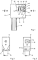
- the device has a substantially cuboid shape the underside is bevelled on both sides 12.
- the area of the housing 12 is on the underside thereof 14 attached handle 16 provided in the form of a round bar, which protrudes downwards in the middle of the housing.
- On the front side 18 of the housing 12 is the one under investigation Eye 20 when measuring opposite window 22.
- At the Rear 24 of the housing 12 are controls 26, control lamps 28 and a monitor 30 for visual observation of the eye 20 arranged during the measurement.
- a plate sits behind a front wall 40 of the housing 12 42, the parts of the optical and electronic components the device carries.
- the plate 42 leaves the window opening 22 free. It can be aligned with the window opening 22 Have opening 44. Through the axis of the opening (s) 22, 44 is defines a measuring axis of the device.
- Retaining rods 46 go from the plate 42 to the interior of the housing for two boards 48, 50, which are parallel to each other at a distance extend the plate level. That adjacent to the plate 42 front board 48 carries, inter alia, a CCD camera 52, whose infrared-sensitive CCD array of the window opening 22nd on the measuring axis lies opposite each other.
- the Electronic 54 with which the CCD camera 52 is connected, is distributed to the front and rear plantines 48, 50.
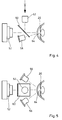
- the device has two infrared light sources 56 that pass through aim the window 22 at the eye 20 to be examined.
- the Infrared light sources 56 are in a horizontal illumination plane arranged through the measuring axis. You sit in symmetrical Arrangement on both sides of the measuring axis on the plate 42 and a radiation direction inclined towards the measuring axis.
- the infrared optically illuminated eye 20 When examining the non-consensual pupil reflex the infrared optically illuminated eye 20 itself becomes optical irritated.
- a flash light source 58 arranged the visible light emits preferably in the yellow spectral range.
- the flash light source 58 sits under the measuring axis on the plate 42. Their direction of radiation is inclined against the measuring axis so that it is on the eye 20 to be examined is aimed.
- the light intensity of the Flash source 58 can be controlled.
- a similar flash light source is used by the consensual pupil reflex the optical stimulus of one eye of the test subject, while the other eye is observed infrared optically (not shown).
- the infrared light reflected by the eye 20 falls through the window 22 in the housing 12 again.
- the CCD camera 52 is located on the Plate 42 arranged mirror 60 which is at an angle of Is inclined at 45 ° to the lighting level.
- the mirror 66 reflects about 99% of the falling infrared light above.
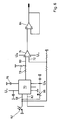
- an infrared detector 62 above the measuring axis high time resolution which is one of the intensity of the pending analog light proportional infrared light.
- the course of this signal over time is at a high frequency digitized and saved for further evaluation, possibly displayed on the monitor 30, on one Pen or plotter issued etc.
- the beat signal is at input 68 of a sample and hold circuit 70 and in parallel at one entrance 72 of an operational amplifier 74.
- the hold capacity of the Sample-and-hold circuit 70 is indicated at 76.
- the output signal the sample-and-hold circuit 70 is over one Voltage divider circuit 78 at the other input 80 of the operational amplifier 74 at.
- the sample-and-hold circuit 70 becomes by a control signal present at the input 82 in standby on "Sample” and immediately before the start of a measurement Pupil reaction switched to "Hold".
- the operational amplifier 74 is thus independent of the offset voltage in standby an output signal level of zero.
- the amplified measurement signal is an analog-digital converter via a further amplifier stage 84 transferred.
- Approx. 1% of the infrared light falling back from the eye 20 is transmitted through mirror 60. It gets to the CCD camera 52 that takes an infrared image of the eye 20 and converts into a visible image. The latter comes on the monitor 30 for display. The user can thereby use the device accurately align with the pupil 64 of the eye 20. That will be through Aiming aid displayed in the monitor image facilitates.
- the user sees whether the eye 20 is open or is closed. He may have blinking and eye movements last but not least has an immediate visual impression of the measured pupil reaction.
- the infrared optics have a shallow depth of field.
- the monitor image the pupil is only adhered to by the focus the infrared optics predetermined measuring distance sharp.
- the measuring person can check this on the monitor and, if necessary, the measuring distance adjust.
- the monitor image can be a Absolute measurement of the pupil size can be used.
- a particular Line can be based on the vertical synchronization signal of the monitor be picked out.
- a fixed line specification is also possible like a line selection by the measuring person.
- the uncoupling of the line signal is with the horizontal synchronization signal triggered by the monitor.
- the level of the stored line signal shows a jump at the pupil edge, which is a discrimination of pupil edge points and thus a determination of the Size of the pupil circle allows.
Landscapes
- Life Sciences & Earth Sciences (AREA)
- Health & Medical Sciences (AREA)
- Medical Informatics (AREA)
- Biophysics (AREA)
- Ophthalmology & Optometry (AREA)
- Engineering & Computer Science (AREA)
- Biomedical Technology (AREA)
- Heart & Thoracic Surgery (AREA)
- Physics & Mathematics (AREA)
- Molecular Biology (AREA)
- Surgery (AREA)
- Animal Behavior & Ethology (AREA)
- General Health & Medical Sciences (AREA)
- Public Health (AREA)
- Veterinary Medicine (AREA)
- Eye Examination Apparatus (AREA)
Claims (16)
- Dispositif de mesure de la réaction d'un oeil au niveau pupillaire, comprenant au moins une source de lumière infrarouge (56) éclairant l'oeil (20), comprenant un convertisseur d'image à infrarouge qui reçoit la lumière infrarouge réfléchie par l'oeil et envoie une image de l'oeil à un moniteur optique (30) pour qu'il l'affiche, comprenant un diviseur de faisceau placé dans la trajectoire de la lumière infrarouge réfléchie, et comprenant un dispositif produisant un stimulus, caractérisé en ce qu'il comporte deux détecteurs d'infrarouges, à savoir le convertisseur d'image à infrarouge et un détecteur d'infrarouges (62) à haut pouvoir de résolution dans le temps, non limité par la fréquence de l'image vidéo, qui reçoit la lumière infrarouge réfléchie par l'oeil et produit un signal correspondant à l'intensité lumineuse existante.
- Dispositif selon la revendication 1, caractérisé en ce que le diviseur de faisceau est un miroir (60) placé entre l'oeil (20) et le convertisseur d'image à infrarouge, laissant partiellement passer la lumière infrarouge.
- Dispositif selon la revendication 2, caractérisé en ce que le convertisseur d'image à infrarouge reçoit de la lumière infrarouge transmise par le miroir (60) et le détecteur (62) reçoit de la lumière infrarouge réfléchie par le miroir (60).
- Dispositif selon la revendication 2, caractérisé en ce que le détecteur reçoit de la lumière infrarouge transmise par le miroir et le convertisseur d'image à infrarouge reçoit de la lumière infrarouge réfléchie par le miroir.
- Dispositif selon l'une des revendications 1 à 4, caractérisé en ce que le miroir (60) forme, avec l'axe de mesure, un angle de 45°.
- Dispositif selon l'une des revendications 1 à 5, caractérisé en ce que le convertisseur d'image à infrarouge est situé à l'opposé de l'oeil (20), sur l'axe de mesure.
- Dispositif selon l'une des revendications 1 à 6, caractérisé en ce que le convertisseur d'image à infrarouge est une caméra à couplage de charge (CCD) (52).
- Dispositif selon l'une des revendications 1 à 7, caractérisé en ce qu'une source de lumière infrarouge (56) est respectivement placée de part et d'autre de l'axe de mesure dans un plan d'éclairage traversant celui-ci, en ce que le miroir (60) forme un angle de 45° avec le plan d'éclairage, et en ce que le détecteur (62) est placé sur l'axe de mesure, avec sa direction de visée perpendiculaire au plan d'éclairage.
- Dispositif selon l'une des revendications 1 à 8, caractérisé en ce qu'il est pourvu, pour un stimulus optique de l'oeil observé (20) ou de l'autre oeil d'une personne testée, d'une source de lumière de flash (58) dont l'intensité lumineuse est, de préférence, réglable.
- Dispositif selon l'une des revendications 1 à 9, caractérisé en ce que la source de lumière de flash (58) est située, du côté du plan d'éclairage qui est opposé au détecteur (62), sous l'axe de mesure.
- Dispositif selon l'une des revendications 1 à 10, caractérisé en ce que la direction du faisceau de la/des source(s) de lumière infrarouge (56) et/ou de la source de lumière de flash (58) est inclinée en direction de l'axe de mesure.
- Dispositif selon l'une des revendications 1 à 11, caractérisé en ce que la sortie du signal du détecteur à infrarouge (62) est reliée à un échantillonneur (70).
- Dispositif selon la revendication 12, caractérisé en ce que la sortie du signal du détecteur d'infrarouges (62), parallèlement à l'entrée (68) de l'échantillonneur (70), est reliée à l'entrée (72) d'un amplificateur opérationnel (74) et la sortie de l'échantillonneur (70) est reliée à l'autre entrée (80) de l'amplificateur opérationnel (74), et en ce que l'échantillonneur (70), en position d'attente, peut être commuté sur "échantillonner" et sur "maintien" pour la procédure de mesure.
- Dispositif selon l'une des revendications 1 à 13, caractérisé en ce qu'il comporte un boitier (12), destiné à être tenu à la main, avec une fenêtre (22) sur la face avant (18) orientée en direction de l'oeil (20), et avec un moniteur (30), de préférence sur la face arrière (24) opposée.
- Dispositif selon l'une des revendications 1 à 14, caractérisé en ce que l'optique pour rayons infrarouges a une faible profondeur de champ, de sorte que l'image que donne le moniteur de la pupille n'est nette qu'à une distance de mesure bien définie.
- Dispositif selon l'une des revendications 1 à 15, caractérisé en ce que le signal transmis par la ligne d'au moins une ligne du moniteur peut être capté et conservé en mémoire.
Applications Claiming Priority (3)
| Application Number | Priority Date | Filing Date | Title |
|---|---|---|---|
| DE4419489A DE4419489A1 (de) | 1994-06-03 | 1994-06-03 | Vorrichtung zum Messen der Pupillenreaktion eines Auges |
| DE4419489 | 1994-06-03 | ||
| PCT/DE1995/000720 WO1995033402A2 (fr) | 1994-06-03 | 1995-06-01 | Systeme permettant de mesurer les reactions d'un ×il au niveau pupillaire |
Publications (2)
| Publication Number | Publication Date |
|---|---|
| EP0762846A2 EP0762846A2 (fr) | 1997-03-19 |
| EP0762846B1 true EP0762846B1 (fr) | 1998-03-04 |
Family
ID=6519748
Family Applications (1)
| Application Number | Title | Priority Date | Filing Date |
|---|---|---|---|
| EP95920746A Expired - Lifetime EP0762846B1 (fr) | 1994-06-03 | 1995-06-01 | Systeme permettant de mesurer les reactions d'un oeil au niveau pupillaire |
Country Status (4)
| Country | Link |
|---|---|
| EP (1) | EP0762846B1 (fr) |
| AU (1) | AU2610495A (fr) |
| DE (2) | DE4419489A1 (fr) |
| WO (1) | WO1995033402A2 (fr) |
Cited By (2)
| Publication number | Priority date | Publication date | Assignee | Title |
|---|---|---|---|---|
| JP2006512126A (ja) * | 2002-12-24 | 2006-04-13 | ニューキャッスル−アプオン−タイン ホスピタルズ エヌエイチエス トラスト | 瞳孔計 |
| EP4364642A1 (fr) | 2022-11-04 | 2024-05-08 | Carl Zeiss Vision International GmbH | Procédés et dispositifs mis en uvre par ordinateur pour déterminer des erreurs de réfraction |
Families Citing this family (7)
| Publication number | Priority date | Publication date | Assignee | Title |
|---|---|---|---|---|
| DE19803158C1 (de) * | 1998-01-28 | 1999-05-06 | Daimler Chrysler Ag | Vorrichtung zur Vigilanzzustandsbestimmung |
| GB2367123A (en) * | 2000-09-20 | 2002-03-27 | Tharaka Gunarathne | Measurement of pupil response |
| DE10154194A1 (de) | 2001-11-07 | 2003-05-22 | Asclepion Meditec Ag | Verfahren und Vorrichtung zur Messung des Dynamischen Verhaltens eines optischen Systems |
| GB2442621B (en) * | 2002-12-24 | 2008-08-20 | Newcastle Upon Tyne Hospitals | A pupilometer |
| DE102005024974B4 (de) * | 2005-05-25 | 2010-04-01 | Freie Universität Berlin | Pupillometrisches Verfahren |
| WO2017003719A2 (fr) | 2015-06-30 | 2017-01-05 | 3M Innovative Properties Company | Dispositif d'éclairage |
| CN112903094B (zh) * | 2020-01-21 | 2022-11-08 | 上海掌门科技有限公司 | 一种用于检测场景光线的方法与设备 |
Family Cites Families (5)
| Publication number | Priority date | Publication date | Assignee | Title |
|---|---|---|---|---|
| US4762410A (en) * | 1983-04-07 | 1988-08-09 | Canon Kabushiki Kaisha | Ophthalmic instrument |
| US4755043A (en) * | 1985-02-15 | 1988-07-05 | Somec, Inc. | Portable scanning digital pupillometer and method of use thereof |
| US4850691A (en) * | 1987-03-18 | 1989-07-25 | University Of Illinois | Method and apparatus for determining pupillary response parameters |
| US5187506A (en) * | 1990-09-28 | 1993-02-16 | Fairville Medical Optics Inc. | Method and apparatus for determining physiological parameters based on pupil response |
| US5214455A (en) * | 1991-04-01 | 1993-05-25 | General Electric Company | Objective eye alignment measurement method and system |
-
1994
- 1994-06-03 DE DE4419489A patent/DE4419489A1/de not_active Withdrawn
-
1995
- 1995-06-01 WO PCT/DE1995/000720 patent/WO1995033402A2/fr active IP Right Grant
- 1995-06-01 EP EP95920746A patent/EP0762846B1/fr not_active Expired - Lifetime
- 1995-06-01 DE DE59501567T patent/DE59501567D1/de not_active Expired - Fee Related
- 1995-06-01 AU AU26104/95A patent/AU2610495A/en not_active Abandoned
Cited By (2)
| Publication number | Priority date | Publication date | Assignee | Title |
|---|---|---|---|---|
| JP2006512126A (ja) * | 2002-12-24 | 2006-04-13 | ニューキャッスル−アプオン−タイン ホスピタルズ エヌエイチエス トラスト | 瞳孔計 |
| EP4364642A1 (fr) | 2022-11-04 | 2024-05-08 | Carl Zeiss Vision International GmbH | Procédés et dispositifs mis en uvre par ordinateur pour déterminer des erreurs de réfraction |
Also Published As
| Publication number | Publication date |
|---|---|
| WO1995033402A3 (fr) | 1996-02-01 |
| AU2610495A (en) | 1996-01-04 |
| DE59501567D1 (de) | 1998-04-09 |
| EP0762846A2 (fr) | 1997-03-19 |
| DE4419489A1 (de) | 1995-12-07 |
| WO1995033402A2 (fr) | 1995-12-14 |
Similar Documents
| Publication | Publication Date | Title |
|---|---|---|
| DE3689840T2 (de) | Tragbares gerät zur digitalmessung der pupillengrösse. | |
| DE69317570T2 (de) | Pupillometer | |
| DE69727257T2 (de) | Vorrichtung zur Messung von Blut-Glukose | |
| DE3825789C2 (fr) | ||
| DE60121123T2 (de) | Verfahren und vorrichtung zur messung von refraktiven fehlern eines auges | |
| US5187506A (en) | Method and apparatus for determining physiological parameters based on pupil response | |
| DE69634858T2 (de) | Nichtinvasive blutuntersuchungsvorrichtung | |
| DE3878595T2 (de) | Geraet zur anzeige von augenleiden. | |
| DE2828405A1 (de) | Augenuntersuchungseinrichtung | |
| DE4200741A1 (de) | Einrichtung zum erkennen von karies an zaehnen | |
| DE4215946A1 (de) | Vorrichtung zum ueberwachen physiologischer daten zur erfassung einer drogenbeeintraechtigung | |
| DE102010014775A1 (de) | Vorrichtung und Verfahren zur Bestimmen eines biologischen, chemischen und/oder physikalischen Parameters in lebendem biologischem Gewebe | |
| EP0762846B1 (fr) | Systeme permettant de mesurer les reactions d'un oeil au niveau pupillaire | |
| EP0312736A1 (fr) | Analyseur de profil des surfaces | |
| DE69013366T2 (de) | Fruchtbarkeitsanalysegerät. | |
| DE3624674A1 (de) | Vorrichtung zum objektiven erfassen von veraenderungen der haut | |
| EP1308128A2 (fr) | Dispositif et procédé pour mesurer la réfraction de l'oeil | |
| US7396128B2 (en) | Process and apparatus for examining the visual functions of the eye | |
| EP3612789B1 (fr) | Dispositif de capture d'images oct | |
| DE69404643T2 (de) | Goniophotometer | |
| DE3885341T2 (de) | Gerät zur Diagnostik von Augenleiden. | |
| DE19646236C2 (de) | Vorrichtung zur endoskopischen Diagnose und Behandlung von Gewebe | |
| DE10251345B4 (de) | Verfahren und Vorrichtung zur Untersuchung von Schichten von Geweben in lebenden Tieren mit einem Mikroskop | |
| DE60319319T2 (de) | Augenheilkundegerät | |
| WO1998052309A1 (fr) | Procede et dispositif permettant de mesurer l'attention d'etres vivants au sein d'une pluralite d'etres vivants |
Legal Events
| Date | Code | Title | Description |
|---|---|---|---|
| PUAI | Public reference made under article 153(3) epc to a published international application that has entered the european phase |
Free format text: ORIGINAL CODE: 0009012 |
|
| 17P | Request for examination filed |
Effective date: 19961118 |
|
| AK | Designated contracting states |
Kind code of ref document: A2 Designated state(s): DE ES FR GB IT NL SE |
|
| GRAG | Despatch of communication of intention to grant |
Free format text: ORIGINAL CODE: EPIDOS AGRA |
|
| 17Q | First examination report despatched |
Effective date: 19970414 |
|
| GRAG | Despatch of communication of intention to grant |
Free format text: ORIGINAL CODE: EPIDOS AGRA |
|
| GRAG | Despatch of communication of intention to grant |
Free format text: ORIGINAL CODE: EPIDOS AGRA |
|
| GRAH | Despatch of communication of intention to grant a patent |
Free format text: ORIGINAL CODE: EPIDOS IGRA |
|
| GRAH | Despatch of communication of intention to grant a patent |
Free format text: ORIGINAL CODE: EPIDOS IGRA |
|
| GRAA | (expected) grant |
Free format text: ORIGINAL CODE: 0009210 |
|
| AK | Designated contracting states |
Kind code of ref document: B1 Designated state(s): DE ES FR GB IT NL SE |
|
| PG25 | Lapsed in a contracting state [announced via postgrant information from national office to epo] |
Ref country code: ES Free format text: THE PATENT HAS BEEN ANNULLED BY A DECISION OF A NATIONAL AUTHORITY Effective date: 19980304 |
|
| REF | Corresponds to: |
Ref document number: 59501567 Country of ref document: DE Date of ref document: 19980409 |
|
| ITF | It: translation for a ep patent filed | ||
| GBT | Gb: translation of ep patent filed (gb section 77(6)(a)/1977) |
Effective date: 19980528 |
|
| ET | Fr: translation filed | ||
| PLBE | No opposition filed within time limit |
Free format text: ORIGINAL CODE: 0009261 |
|
| STAA | Information on the status of an ep patent application or granted ep patent |
Free format text: STATUS: NO OPPOSITION FILED WITHIN TIME LIMIT |
|
| 26N | No opposition filed | ||
| REG | Reference to a national code |
Ref country code: GB Ref legal event code: IF02 |
|
| PGFP | Annual fee paid to national office [announced via postgrant information from national office to epo] |
Ref country code: GB Payment date: 20020412 Year of fee payment: 8 Ref country code: FR Payment date: 20020412 Year of fee payment: 8 |
|
| PGFP | Annual fee paid to national office [announced via postgrant information from national office to epo] |
Ref country code: SE Payment date: 20020426 Year of fee payment: 8 |
|
| PGFP | Annual fee paid to national office [announced via postgrant information from national office to epo] |
Ref country code: DE Payment date: 20020503 Year of fee payment: 8 |
|
| PGFP | Annual fee paid to national office [announced via postgrant information from national office to epo] |
Ref country code: NL Payment date: 20020628 Year of fee payment: 8 |
|
| PG25 | Lapsed in a contracting state [announced via postgrant information from national office to epo] |
Ref country code: GB Free format text: LAPSE BECAUSE OF NON-PAYMENT OF DUE FEES Effective date: 20030601 |
|
| PG25 | Lapsed in a contracting state [announced via postgrant information from national office to epo] |
Ref country code: SE Free format text: LAPSE BECAUSE OF NON-PAYMENT OF DUE FEES Effective date: 20030602 |
|
| PG25 | Lapsed in a contracting state [announced via postgrant information from national office to epo] |
Ref country code: NL Free format text: LAPSE BECAUSE OF NON-PAYMENT OF DUE FEES Effective date: 20040101 Ref country code: DE Free format text: LAPSE BECAUSE OF NON-PAYMENT OF DUE FEES Effective date: 20040101 |
|
| GBPC | Gb: european patent ceased through non-payment of renewal fee |
Effective date: 20030601 |
|
| EUG | Se: european patent has lapsed | ||
| PG25 | Lapsed in a contracting state [announced via postgrant information from national office to epo] |
Ref country code: FR Free format text: LAPSE BECAUSE OF NON-PAYMENT OF DUE FEES Effective date: 20040227 |
|
| NLV4 | Nl: lapsed or anulled due to non-payment of the annual fee |
Effective date: 20040101 |
|
| REG | Reference to a national code |
Ref country code: FR Ref legal event code: ST |
|
| PG25 | Lapsed in a contracting state [announced via postgrant information from national office to epo] |
Ref country code: IT Free format text: LAPSE BECAUSE OF NON-PAYMENT OF DUE FEES;WARNING: LAPSES OF ITALIAN PATENTS WITH EFFECTIVE DATE BEFORE 2007 MAY HAVE OCCURRED AT ANY TIME BEFORE 2007. THE CORRECT EFFECTIVE DATE MAY BE DIFFERENT FROM THE ONE RECORDED. Effective date: 20050601 |