EP0762181A1 - Perfectionnement au dispositif d'affichage comportant un système d'éclairage arrière fournissant une lumière collimatée - Google Patents
Perfectionnement au dispositif d'affichage comportant un système d'éclairage arrière fournissant une lumière collimatée Download PDFInfo
- Publication number
- EP0762181A1 EP0762181A1 EP96401747A EP96401747A EP0762181A1 EP 0762181 A1 EP0762181 A1 EP 0762181A1 EP 96401747 A EP96401747 A EP 96401747A EP 96401747 A EP96401747 A EP 96401747A EP 0762181 A1 EP0762181 A1 EP 0762181A1
- Authority
- EP
- European Patent Office
- Prior art keywords
- light
- display
- black matrix
- distributing
- angularly
- Prior art date
- Legal status (The legal status is an assumption and is not a legal conclusion. Google has not performed a legal analysis and makes no representation as to the accuracy of the status listed.)
- Withdrawn
Links
- 239000011159 matrix material Substances 0.000 claims abstract description 25
- 239000000758 substrate Substances 0.000 claims abstract description 17
- 238000000034 method Methods 0.000 claims abstract description 6
- 230000000694 effects Effects 0.000 claims abstract description 4
- 238000001914 filtration Methods 0.000 claims abstract description 4
- 239000004973 liquid crystal related substance Substances 0.000 claims description 19
- 238000001093 holography Methods 0.000 abstract 1
- 230000005540 biological transmission Effects 0.000 description 9
- 238000009792 diffusion process Methods 0.000 description 6
- 239000011521 glass Substances 0.000 description 4
- 239000000463 material Substances 0.000 description 4
- 230000010287 polarization Effects 0.000 description 3
- 229910052782 aluminium Inorganic materials 0.000 description 2
- XAGFODPZIPBFFR-UHFFFAOYSA-N aluminium Chemical compound [Al] XAGFODPZIPBFFR-UHFFFAOYSA-N 0.000 description 2
- 229920000106 Liquid crystal polymer Polymers 0.000 description 1
- 239000004977 Liquid-crystal polymers (LCPs) Substances 0.000 description 1
- NIXOWILDQLNWCW-UHFFFAOYSA-N acrylic acid group Chemical group C(C=C)(=O)O NIXOWILDQLNWCW-UHFFFAOYSA-N 0.000 description 1
- 230000015556 catabolic process Effects 0.000 description 1
- 150000001875 compounds Chemical class 0.000 description 1
- 238000006731 degradation reaction Methods 0.000 description 1
- 239000006185 dispersion Substances 0.000 description 1
- 230000004907 flux Effects 0.000 description 1
- 229910052736 halogen Inorganic materials 0.000 description 1
- 150000002367 halogens Chemical class 0.000 description 1
- 229910052751 metal Inorganic materials 0.000 description 1
- 239000002184 metal Substances 0.000 description 1
- 230000003287 optical effect Effects 0.000 description 1
- 239000011368 organic material Substances 0.000 description 1
- 239000007787 solid Substances 0.000 description 1
- 239000012780 transparent material Substances 0.000 description 1
- WFKWXMTUELFFGS-UHFFFAOYSA-N tungsten Chemical compound [W] WFKWXMTUELFFGS-UHFFFAOYSA-N 0.000 description 1
- 229910052721 tungsten Inorganic materials 0.000 description 1
- 239000010937 tungsten Substances 0.000 description 1
Images


Classifications
-
- G—PHYSICS
- G02—OPTICS
- G02F—OPTICAL DEVICES OR ARRANGEMENTS FOR THE CONTROL OF LIGHT BY MODIFICATION OF THE OPTICAL PROPERTIES OF THE MEDIA OF THE ELEMENTS INVOLVED THEREIN; NON-LINEAR OPTICS; FREQUENCY-CHANGING OF LIGHT; OPTICAL LOGIC ELEMENTS; OPTICAL ANALOGUE/DIGITAL CONVERTERS
- G02F1/00—Devices or arrangements for the control of the intensity, colour, phase, polarisation or direction of light arriving from an independent light source, e.g. switching, gating or modulating; Non-linear optics
- G02F1/01—Devices or arrangements for the control of the intensity, colour, phase, polarisation or direction of light arriving from an independent light source, e.g. switching, gating or modulating; Non-linear optics for the control of the intensity, phase, polarisation or colour
- G02F1/13—Devices or arrangements for the control of the intensity, colour, phase, polarisation or direction of light arriving from an independent light source, e.g. switching, gating or modulating; Non-linear optics for the control of the intensity, phase, polarisation or colour based on liquid crystals, e.g. single liquid crystal display cells
- G02F1/133—Constructional arrangements; Operation of liquid crystal cells; Circuit arrangements
- G02F1/1333—Constructional arrangements; Manufacturing methods
- G02F1/1335—Structural association of cells with optical devices, e.g. polarisers or reflectors
- G02F1/133504—Diffusing, scattering, diffracting elements
-
- G—PHYSICS
- G02—OPTICS
- G02F—OPTICAL DEVICES OR ARRANGEMENTS FOR THE CONTROL OF LIGHT BY MODIFICATION OF THE OPTICAL PROPERTIES OF THE MEDIA OF THE ELEMENTS INVOLVED THEREIN; NON-LINEAR OPTICS; FREQUENCY-CHANGING OF LIGHT; OPTICAL LOGIC ELEMENTS; OPTICAL ANALOGUE/DIGITAL CONVERTERS
- G02F1/00—Devices or arrangements for the control of the intensity, colour, phase, polarisation or direction of light arriving from an independent light source, e.g. switching, gating or modulating; Non-linear optics
- G02F1/01—Devices or arrangements for the control of the intensity, colour, phase, polarisation or direction of light arriving from an independent light source, e.g. switching, gating or modulating; Non-linear optics for the control of the intensity, phase, polarisation or colour
- G02F1/13—Devices or arrangements for the control of the intensity, colour, phase, polarisation or direction of light arriving from an independent light source, e.g. switching, gating or modulating; Non-linear optics for the control of the intensity, phase, polarisation or colour based on liquid crystals, e.g. single liquid crystal display cells
- G02F1/133—Constructional arrangements; Operation of liquid crystal cells; Circuit arrangements
- G02F1/1333—Constructional arrangements; Manufacturing methods
- G02F1/1335—Structural association of cells with optical devices, e.g. polarisers or reflectors
- G02F1/133509—Filters, e.g. light shielding masks
- G02F1/133514—Colour filters
Definitions
- the present invention relates to improvements to a display device, more particularly of the liquid crystal display type, used in the transmission mode and backlit by a lighting system providing collimated light.
- the present invention therefore relates to a display device comprising a rear lighting system providing collimated light, a transmissive electro-optical modulator of the liquid crystal display type and a means for distributing the light angularly, characterized in that the distance between the means for angularly distributing the light and the display is chosen to obtain a spatial filtering effect.
- the present invention also relates to a display device comprising a rear lighting system providing collimated light, a transmissive electro-optical modulator of the type liquid crystal display and means for distributing the light angularly, characterized in that a layer of colored filters is positioned between the display and the means for distributing the light angularly.
- This layer of colored filters can comprise a black matrix layer called "black matrix”.
- one of the transparent substrates forming the liquid crystal display incorporates a row of one or two dimensions of microlenses, each microlens forming the image of the associated pixel element of the display on the broadcast screen.
- one of the transparent substrates forming the liquid crystal display incorporates a row with one or two dimensions of micro-lenses, each micro-lens collecting the light entering the associated pixel element of the display.
- FIG. 1 the rear lighting system referenced 10 makes it possible to obtain highly collimated light whose rays are referenced 11.
- this device consists essentially of a liquid crystal display, referenced LCD in FIG. 1 which, in known manner, consists of a layer of liquid crystal a few micrometers thick 100 enclosed between two transparent substrates 101 and 102 with polarizers 103 and 104 fixed to the walls.
- Each image forming element known under the term pixel consists of an active surface 105 surrounded by an inactive surface which is typically covered by a black matrix 106 known by the term "black-matrix". This Black Matrix makes it possible to avoid any light leaks in the black state of the pixel.
- the liquid crystal is addressed by transparent pixel electrodes 107 in the active surface.
- a means for distributing the light angularly 110 is fixed to the polarizer 103 and the assembly is illuminated by the lighting system 10 giving collimated light. In this case and as shown in FIG.
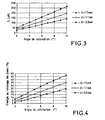
- the image of the active surface 105 formed on the diffusion screen 110 has an intensity distribution as shown in FIG. 2.
- the dispersion of a pixel can be characterized by the distance S defined in FIG. 2 and which gives the distance on the diffuser 110 from the original pixel where the intensity reaches 0.
- FIGS. 3 and 4 show the said distance S as defined above as a function of the collimation angle ⁇ for different thicknesses D corresponding to the thickness of the transparent substrate 102 plus the thickness of polarizer 103, .as well as the energy in the vicinity of a pixel as a function of the collimation angle ⁇ for these different thicknesses 2.
- the value D 1.5 mm corresponds to the most widely used glass thickness with a normal polarizer 0.4 mm thick.
- D 1.5 mm
- a collimation angle of 4 ° is perfectly acceptable.
- Such a collimation angle can be easily obtained with a halogen lamp, a tungsten lamp or a fluorescent tube in a rear lighting device as described above.
- this diffusion effect can be used in order to obtain spatial filtering of the display.
- the distance D as well as the collimation angle ⁇ can be adjusted adequately without affecting the resolution of the display.
- the rear lighting system used to obtain collimated light can be any system known in the literature. It can also be a system such as that described in the French patent application filed on the same day having the title "Rear lighting system for transmissive electro-optical modulator and display device comprising such a lighting system”.
- This light source is surrounded over the entire length of the tube 1 by a reflection means 2 making it possible to return the light rays emitted by the tube in a first direction called x.
- the reflector 2 preferably has the form of an optical concentrator known for example under the term CPC (from the English term: compound parabolic concentrator).
- This reflector 2 is extended by a light transmission means 3 positioned at the outlet of the reflector so as to transport the light rays in the direction x.
- This light transmission means 3 is preferably a waveguide made of a transparent material which can for example be glass or a polymeric organic material such as an acrylic material.
- the height of the waveguide 3 is preferably greater than or equal to the circumference of the light source 1 so as to obtain maximum efficiency in the transmission of light.
- the waveguide 3 has on its lower part a micro-prismatic structure 4 which specularly reflects the light rays so as to send them in the z direction.
- This micro-prismatic structure 4 is either a part of the waveguide 3 or is made of an identical or similar material and paired in index to the waveguide.
- the light rays are reflected by said micro-prismatic structure either by total internal reflection, or by reflection on a metal layer, preferably aluminum, deposited on the outer surface of said micro-prismatic structure.
- this end of the waveguide is coated with a reflective material 5, preferably aluminum.
- a reflective material 5 preferably aluminum.
- the light rays transporting inside the waveguide are specularly reflected by the micro-prismatic structure 4 and returned in the direction z. It is also possible, according to another embodiment of the present invention, to place a second light source with its reflector on said end of the waveguide instead of layer 5 in order to increase the light flux of the system.
- a collimation means 6 making it possible to collimate the light rays at the output at least in a plane yz, as shown in FIG. 5, therefore the light referenced 7 extracted from the waveguide by specular reflection is collimated in the zy plane by means of this special collimation means 6, this light already being collimated in the xz plane.
- FIG. 6 another embodiment of a display device using a lighting system giving collimated light making it possible to use a particular structure for the colored filters.
- the colored filters which in a conventional liquid crystal screen are placed inside one of the transparent substrates, have been positioned outside as represented by the reference 117 in FIG. 6.
- the use of colored filters 117 outside the substrate 102 makes it possible to use inexpensive colored filters, for example simple photographic films which have been exposed to the desired pixel structure.
- a layer of colored filters 117 incorporating a black matrix 118 is placed outside the transparent substrate 102 followed by the polarizer 103 and the diffusion screen 110.
- the color filter can also be placed in front of the polarizer 103.
- an additional black matrix 119 will be used on the transparent substrate to prevent any light leakage in the black state.
- its width is determined by the fact that light from a colored pixel must not penetrate inside the adjacent pixel on the broadcast screen.
- FIGS. 7a to 7c Three arrangements are possible as shown in FIGS. 7a to 7c in which P represents the pitch of an individual colored pixel.
- the black matrix is produced only on the layer of colored filters 117.
- FIG. 7b there is shown a black matrix 119 produced inside the transparent substrate.
- a black matrix 117 is produced on the layer of color filters 118 and a black matrix 119 is produced outside the transparent substrate.
- the solution shown in Figure 7c is in most cases the preferred solution because it gives the highest transmission.
- the table below representing the distance S and the transmission of the black matrices 118 and 119 assuming a pixel pitch of 100 ⁇ m x 300 ⁇ m and for two different thicknesses of the transparent substrates has been represented.
- the color filter layer comprising a black matrix as shown in Figure 6 for example, can be obtained in many ways.
- a photographic process can be used in which a photographic film is illuminated with the desired color filter structure and further development.
- a printing process can be used.
- the color filter layer can also be obtained using a dichroic interference filter or a holographic process or birefringent interference using a liquid crystal polymer.
- the diffusion screen can be a diffusion screen having non-Lambertian characteristics directing the light according to a predetermined angular range which increases the luminance in this range compared to a Lambertian diffuser.
- the angular distribution of the collimated light provided by the rear lighting system is chosen so as to be in accordance with the contrast characteristic of the liquid crystal display.
- the The system's light output can be improved if a row of microlenses is incorporated in the transparent substrate 102, each forming the image of the associated pixel on the screen 110. In this case, the black matrix 118 is redundant.
- rows of microlenses can be incorporated into or on the transparent substrate 101 in order to collect all the light incident on the active surface 105 of the associated pixel.
- Said rows of microlenses can be one-dimensional rows of cylindrical lenses, the number of lenses corresponding to the number of pixels in the horizontal and vertical directions. It is also possible to use two-dimensional rows of the same dimension as the matrix formed by the pixels of the liquid crystal screen.
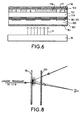
- the contrast under ambient light is often limited by the backscattering of the element 110.
- the element 110 for example in the case of a frosted or a holographic diffuser
- the contrast in ambient light can be considerably increased (up to a factor of 4) by putting a polarizer 120 after the diffusing means 110 as shown in Figure 8.
- the polarizer 120 can take the function of the output polarizer of the LCD, which makes it possible to remove the latter in order to improve the luminance of the display system.
Landscapes
- Physics & Mathematics (AREA)
- Nonlinear Science (AREA)
- Mathematical Physics (AREA)
- Chemical & Material Sciences (AREA)
- Crystallography & Structural Chemistry (AREA)
- General Physics & Mathematics (AREA)
- Optics & Photonics (AREA)
- Liquid Crystal (AREA)
Applications Claiming Priority (2)
| Application Number | Priority Date | Filing Date | Title |
|---|---|---|---|
| FR9509753A FR2737799B1 (fr) | 1995-08-11 | 1995-08-11 | Perfectionnement au dispositif d'affichage comportant un systeme d'eclairage arriere fournissant une lumiere collimatee |
| FR9509753 | 1995-08-11 |
Publications (1)
| Publication Number | Publication Date |
|---|---|
| EP0762181A1 true EP0762181A1 (fr) | 1997-03-12 |
Family
ID=9481882
Family Applications (1)
| Application Number | Title | Priority Date | Filing Date |
|---|---|---|---|
| EP96401747A Withdrawn EP0762181A1 (fr) | 1995-08-11 | 1996-08-07 | Perfectionnement au dispositif d'affichage comportant un système d'éclairage arrière fournissant une lumière collimatée |
Country Status (4)
| Country | Link |
|---|---|
| US (1) | US5990993A (enExample) |
| EP (1) | EP0762181A1 (enExample) |
| JP (1) | JPH09120060A (enExample) |
| FR (1) | FR2737799B1 (enExample) |
Cited By (2)
| Publication number | Priority date | Publication date | Assignee | Title |
|---|---|---|---|---|
| WO1999042896A1 (de) * | 1998-02-20 | 1999-08-26 | F.O.B. Gmbh Gesellschaft Zur Fertigung Farbiger Optoelektronischer Bauelemente | Optischer schalter |
| EP2020614A1 (en) * | 2007-07-27 | 2009-02-04 | Samsung Electronics Co., Ltd. | Collimating light guide plate, diffusing unit, and display apparatus employing the same |
Families Citing this family (9)
| Publication number | Priority date | Publication date | Assignee | Title |
|---|---|---|---|---|
| EP1018058A2 (en) * | 1997-03-06 | 2000-07-12 | Nashua Corporation | Improved display |
| US6816225B2 (en) * | 2001-06-26 | 2004-11-09 | International Business Machines Corporation | LCD cell construction by mechanical thinning of a color filter substrate |
| KR20030069285A (ko) * | 2002-02-19 | 2003-08-27 | 삼성전자주식회사 | 액정 표시 장치 |
| US20040046730A1 (en) * | 2002-08-21 | 2004-03-11 | Kazuhiro Miyashita | LCD (liquid crystal display) with a back light source characterized by light source local penetration |
| US7388631B2 (en) * | 2002-10-10 | 2008-06-17 | Samsung Electronics, Co., Ltd. | Parallax compensating color filter and black mask for display apparatus |
| WO2007052565A1 (ja) * | 2005-11-04 | 2007-05-10 | Sharp Kabushiki Kaisha | 液晶表示装置 |
| CN101563644A (zh) * | 2006-12-11 | 2009-10-21 | 夏普株式会社 | 液晶显示装置 |
| CN102830539B (zh) * | 2012-09-06 | 2015-09-02 | 京东方科技集团股份有限公司 | 液晶显示装置 |
| CN105929591B (zh) | 2016-07-08 | 2019-04-05 | 京东方科技集团股份有限公司 | 量子点显示基板及其制造方法和量子点显示装置 |
Citations (6)
| Publication number | Priority date | Publication date | Assignee | Title |
|---|---|---|---|---|
| EP0337555A1 (en) * | 1988-04-13 | 1989-10-18 | Koninklijke Philips Electronics N.V. | Display device |
| EP0353069A2 (en) * | 1988-07-28 | 1990-01-31 | Kabushiki Kaisha Toshiba | Transmission liquid crystal display apparatus |
| EP0371398A2 (en) * | 1988-11-26 | 1990-06-06 | Toppan Printing Co., Ltd. | Color filter for multi-color liquid-crystal display panel |
| EP0396824A1 (en) * | 1989-04-13 | 1990-11-14 | Agfa-Gevaert N.V. | Process for the production of a multicolour liquid crystal display device |
| JPH06148627A (ja) * | 1992-11-05 | 1994-05-27 | Matsushita Electric Ind Co Ltd | 投写型カラー液晶表示装置 |
| WO1994020879A1 (en) * | 1993-03-04 | 1994-09-15 | Honeywell Inc. | Patterned dichroic filters for color liquid crystal display chromaticity enhancement |
Family Cites Families (15)
| Publication number | Priority date | Publication date | Assignee | Title |
|---|---|---|---|---|
| DE2329618A1 (de) * | 1973-06-09 | 1975-01-02 | Fraunhofer Ges Forschung | Anordnung zur vielfarbigen anzeige, bestehend aus lichtquelle und linearpolarisationsfilter |
| US3854815A (en) * | 1973-11-09 | 1974-12-17 | Logetronics Inc | Graphic arts camera flashing attachments |
| US4171874A (en) * | 1975-02-03 | 1979-10-23 | General Electric Company | Evenly illuminated display devices |
| IL70116A (en) * | 1983-11-02 | 1987-02-27 | Stolov Michael | Liquid crystal device for displaying multicolor images |
| JPS6280626A (ja) * | 1985-10-04 | 1987-04-14 | Hosiden Electronics Co Ltd | 液晶表示素子 |
| JPH0642126B2 (ja) * | 1988-10-26 | 1994-06-01 | シャープ株式会社 | 投影型画像表示装置 |
| US5046793A (en) * | 1989-05-26 | 1991-09-10 | Litton Systems, Inc. | Chromatically corrected directional diffusing screen |
| TW218040B (enExample) * | 1990-09-07 | 1993-12-21 | Sharp Kk | |
| US5528397A (en) * | 1991-12-03 | 1996-06-18 | Kopin Corporation | Single crystal silicon transistors for display panels |
| US5258325A (en) * | 1990-12-31 | 1993-11-02 | Kopin Corporation | Method for manufacturing a semiconductor device using a circuit transfer film |
| JP2856612B2 (ja) * | 1992-10-12 | 1999-02-10 | シャープ株式会社 | ホログラフィック・ステレオグラム記録用投影装置 |
| JPH06130214A (ja) * | 1992-10-12 | 1994-05-13 | Nissha Printing Co Ltd | 液晶用ガラス基板、tft液晶用カラーフィルター、プロジェクション用tft液晶表示装置、カラーtft液晶表示装置 |
| US5561538A (en) * | 1992-11-17 | 1996-10-01 | Sharp Kabushiki Kaisha | Direct-view display apparatus |
| US5501900A (en) * | 1993-03-03 | 1996-03-26 | Dai Nippon Printing Co., Ltd. | Black matrix substrate, and color filter and liquid crystal display device using the same |
| US5594561A (en) * | 1993-03-31 | 1997-01-14 | Palomar Technologies Corporation | Flat panel display with elliptical diffuser and fiber optic plate |
-
1995
- 1995-08-11 FR FR9509753A patent/FR2737799B1/fr not_active Expired - Fee Related
-
1996
- 1996-08-01 US US08/690,900 patent/US5990993A/en not_active Expired - Fee Related
- 1996-08-07 JP JP8208337A patent/JPH09120060A/ja active Pending
- 1996-08-07 EP EP96401747A patent/EP0762181A1/fr not_active Withdrawn
Patent Citations (6)
| Publication number | Priority date | Publication date | Assignee | Title |
|---|---|---|---|---|
| EP0337555A1 (en) * | 1988-04-13 | 1989-10-18 | Koninklijke Philips Electronics N.V. | Display device |
| EP0353069A2 (en) * | 1988-07-28 | 1990-01-31 | Kabushiki Kaisha Toshiba | Transmission liquid crystal display apparatus |
| EP0371398A2 (en) * | 1988-11-26 | 1990-06-06 | Toppan Printing Co., Ltd. | Color filter for multi-color liquid-crystal display panel |
| EP0396824A1 (en) * | 1989-04-13 | 1990-11-14 | Agfa-Gevaert N.V. | Process for the production of a multicolour liquid crystal display device |
| JPH06148627A (ja) * | 1992-11-05 | 1994-05-27 | Matsushita Electric Ind Co Ltd | 投写型カラー液晶表示装置 |
| WO1994020879A1 (en) * | 1993-03-04 | 1994-09-15 | Honeywell Inc. | Patterned dichroic filters for color liquid crystal display chromaticity enhancement |
Non-Patent Citations (1)
| Title |
|---|
| PATENT ABSTRACTS OF JAPAN vol. 18, no. 454 (P - 1791) 24 August 1994 (1994-08-24) * |
Cited By (3)
| Publication number | Priority date | Publication date | Assignee | Title |
|---|---|---|---|---|
| WO1999042896A1 (de) * | 1998-02-20 | 1999-08-26 | F.O.B. Gmbh Gesellschaft Zur Fertigung Farbiger Optoelektronischer Bauelemente | Optischer schalter |
| EP2020614A1 (en) * | 2007-07-27 | 2009-02-04 | Samsung Electronics Co., Ltd. | Collimating light guide plate, diffusing unit, and display apparatus employing the same |
| US9383503B2 (en) | 2007-07-27 | 2016-07-05 | Samsung Display Co., Ltd. | Collimating light guide plate, diffusing unit, and display apparatus employing the same |
Also Published As
| Publication number | Publication date |
|---|---|
| FR2737799A1 (fr) | 1997-02-14 |
| JPH09120060A (ja) | 1997-05-06 |
| US5990993A (en) | 1999-11-23 |
| FR2737799B1 (fr) | 1997-10-17 |
Similar Documents
| Publication | Publication Date | Title |
|---|---|---|
| EP0633702B1 (fr) | Dispositif de visualisation couleurs | |
| FR2751434A1 (fr) | Dispositif d'affichage a cristal liquide a micro-lentilles | |
| EP0547949B1 (fr) | Séparateur de polarisation optique et application à un système de visualisation | |
| EP0762182B1 (fr) | Système d'éclairage arrière pour modulateur électro-optique et dispositif d'affichage comportant un tel système d'éclairage | |
| EP0425371B1 (fr) | Procédé de fabrication d'un module agrandisseur d'images pour panneaux lumineux à fibres optiques | |
| US5929956A (en) | Reflection type diffusing liquid crystal display with selective reflecting means located between the substrates | |
| EP0880724A1 (fr) | Dispositif de visualisation et ecran plat de television utilisant ce dispositif | |
| FR2793043A1 (fr) | Ecran de projection | |
| JPH08505716A (ja) | 反射ホログラフ光素子からなる液晶ディスプレイ | |
| EP0740477B1 (fr) | Dispositif de séparation de polarisation et application à un système d'éclairement d'un écran à cristal liquide | |
| EP0762181A1 (fr) | Perfectionnement au dispositif d'affichage comportant un système d'éclairage arrière fournissant une lumière collimatée | |
| FR2782829A1 (fr) | Panneaux d'affichage lumineux | |
| EP0756192A1 (fr) | Ecran de visualisation à cristal liquide | |
| EP0740476B1 (fr) | Dispositif de séparation de polarisations et application à un système d'éclairement d'un écran à cristal liquide | |
| FR2722305A1 (fr) | Dispositif d'eclairage d'afficheur a cristaux liquides et son procede de fabrication | |
| EP0757274A1 (fr) | Dispositif optique de polarisation et système de projection à valve à cristaux liquides utilisant un tel dispositif optique | |
| EP0937273B1 (fr) | Dispositif compact d'illumination | |
| FR2706666A1 (fr) | Panneau d'affichage à cristaux liquides et projecteur à cristaux liquides utilisant ce dernier. | |
| FR2705484A1 (fr) | Dispositif d'affichage. | |
| WO2015040288A1 (fr) | Dispositif catadioptrique améliorant la visualisation d'une image placée devant un capteur solaire | |
| FR2607301A1 (fr) | Dispositif d'affichage modulaire a cristaux liquides | |
| FR3082011A1 (fr) | Dispositif de generation d'images et afficheur tete-haute comprenant un tel dispositif | |
| EP4508488A1 (fr) | Dispositif de retro-eclairage et generateur d'images | |
| FR2760856A1 (fr) | Dispositif d'eclairement | |
| FR3021800A1 (fr) | Dispositif d'affichage reflectif a tres haute luminosite et a surface photovoltaique integree |
Legal Events
| Date | Code | Title | Description |
|---|---|---|---|
| PUAI | Public reference made under article 153(3) epc to a published international application that has entered the european phase |
Free format text: ORIGINAL CODE: 0009012 |
|
| AK | Designated contracting states |
Kind code of ref document: A1 Designated state(s): DE FR GB |
|
| 17P | Request for examination filed |
Effective date: 19970904 |
|
| RAP1 | Party data changed (applicant data changed or rights of an application transferred) |
Owner name: THOMSON MULTIMEDIA |
|
| STAA | Information on the status of an ep patent application or granted ep patent |
Free format text: STATUS: THE APPLICATION HAS BEEN WITHDRAWN |
|
| 18W | Application withdrawn |
Effective date: 20050224 |