EP0762076A2 - Method and apparatus for material analysis - Google Patents
Method and apparatus for material analysis Download PDFInfo
- Publication number
- EP0762076A2 EP0762076A2 EP96111340A EP96111340A EP0762076A2 EP 0762076 A2 EP0762076 A2 EP 0762076A2 EP 96111340 A EP96111340 A EP 96111340A EP 96111340 A EP96111340 A EP 96111340A EP 0762076 A2 EP0762076 A2 EP 0762076A2
- Authority
- EP
- European Patent Office
- Prior art keywords
- sensor
- measuring device
- strand
- compressed air
- pin
- Prior art date
- Legal status (The legal status is an assumption and is not a legal conclusion. Google has not performed a legal analysis and makes no representation as to the accuracy of the status listed.)
- Withdrawn
Links
- 239000000463 material Substances 0.000 title claims abstract description 53
- 238000000034 method Methods 0.000 title claims description 37
- 238000004458 analytical method Methods 0.000 title claims description 17
- 238000006073 displacement reaction Methods 0.000 claims abstract description 14
- 238000009826 distribution Methods 0.000 claims abstract description 7
- XLYOFNOQVPJJNP-UHFFFAOYSA-N water Substances O XLYOFNOQVPJJNP-UHFFFAOYSA-N 0.000 claims description 12
- 238000005259 measurement Methods 0.000 claims description 7
- 238000002604 ultrasonography Methods 0.000 claims description 5
- 239000000919 ceramic Substances 0.000 claims description 4
- 238000005520 cutting process Methods 0.000 claims description 4
- 230000003628 erosive effect Effects 0.000 claims description 4
- 238000001228 spectrum Methods 0.000 claims description 4
- 230000001419 dependent effect Effects 0.000 claims description 3
- 230000000737 periodic effect Effects 0.000 claims description 3
- 238000007788 roughening Methods 0.000 claims description 2
- 239000004927 clay Substances 0.000 description 14
- 238000010276 construction Methods 0.000 description 2
- 238000004519 manufacturing process Methods 0.000 description 2
- 239000007921 spray Substances 0.000 description 2
- 238000011144 upstream manufacturing Methods 0.000 description 2
- 238000011156 evaluation Methods 0.000 description 1
- 238000011005 laboratory method Methods 0.000 description 1
- 239000002994 raw material Substances 0.000 description 1
- 238000007873 sieving Methods 0.000 description 1
Images
Classifications
-
- G—PHYSICS
- G01—MEASURING; TESTING
- G01N—INVESTIGATING OR ANALYSING MATERIALS BY DETERMINING THEIR CHEMICAL OR PHYSICAL PROPERTIES
- G01N3/00—Investigating strength properties of solid materials by application of mechanical stress
- G01N3/56—Investigating resistance to wear or abrasion
-
- G—PHYSICS
- G01—MEASURING; TESTING
- G01N—INVESTIGATING OR ANALYSING MATERIALS BY DETERMINING THEIR CHEMICAL OR PHYSICAL PROPERTIES
- G01N15/00—Investigating characteristics of particles; Investigating permeability, pore-volume or surface-area of porous materials
- G01N15/02—Investigating particle size or size distribution
-
- G—PHYSICS
- G01—MEASURING; TESTING
- G01N—INVESTIGATING OR ANALYSING MATERIALS BY DETERMINING THEIR CHEMICAL OR PHYSICAL PROPERTIES
- G01N21/00—Investigating or analysing materials by the use of optical means, i.e. using sub-millimetre waves, infrared, visible or ultraviolet light
- G01N21/84—Systems specially adapted for particular applications
- G01N21/85—Investigating moving fluids or granular solids
-
- G—PHYSICS
- G01—MEASURING; TESTING
- G01P—MEASURING LINEAR OR ANGULAR SPEED, ACCELERATION, DECELERATION, OR SHOCK; INDICATING PRESENCE, ABSENCE, OR DIRECTION, OF MOVEMENT
- G01P3/00—Measuring linear or angular speed; Measuring differences of linear or angular speeds
- G01P3/42—Devices characterised by the use of electric or magnetic means
- G01P3/50—Devices characterised by the use of electric or magnetic means for measuring linear speed
- G01P3/54—Devices characterised by the use of electric or magnetic means for measuring linear speed by measuring frequency of generated current or voltage
Definitions
- the invention relates to a method for material analysis, in particular for determining the grain size and / or consistency of a plastic or a pourable material, for example for material analysis of ceramic mass formed as a strand, and a device for using this method.
- the object of the invention is therefore to provide a method and a device for material analysis of a plastic or a pourable good, by means of which it is possible to continuously determine the grain size and / or the consistency of the good, so that deviations from the specified values can be reacted to immediately.
- the construction effort required for this should to be kept low, handling should also be easy to accomplish, but above all the surface profile of a plastic or pourable material, by means of which its grain size and / or consistency can be deduced, should be able to be detected and evaluated.
- the method for material analysis of a plastic or pourable good is characterized in that the good is moved with its surface relative to a measuring device in its longitudinal direction, and that the surface of the good for determining a surface profile during the relative movement with the help of one or more sensors associated with the measuring device is scanned mechanically and / or without contact.
- the material should be moved in its longitudinal direction relative to the measuring device and the high-frequency components of the surface profile moving past the measuring device should be detected for grain size analysis.
- the reference height of the surface of the goods should be checked using e.g. can be determined on this supporting wheel, preferably carrying the sensor, with the aid of the z. B. provided with a rotary encoder wheel during the adjustment movement of the goods a path-dependent signal.
- the surface of the goods can also be measured with the help of a light beam, preferably a laser triangulation displacement sensor.
- a light beam preferably a laser triangulation displacement sensor.
- a compressed air jet or an ultrasound jet can be scanned as a sensor.
- the relief of the surface of the good should furthermore be converted into a length dimension depending on the speed recorded by the measuring device, and the profile data of the surface of the good should be subjected to different filter algorithms such that surface waves are separated into grain fractions and a distribution of the relief heights and / or the peak areas are calculated.
- the surface of the goods should be moistened with water and then roughened or eroded by the compressed air jet.
- the pen or the air jet can act on the surface of the material with two different forces.
- a compressed air jet acts as a sensor of the measuring device on the surface of a plastically deformable material, a measurement of the consistency without water and a grain size analysis with previous moistening should be carried out alternately.
- the device for material analysis of a plastic or a pourable good is characterized by a preferably stationary measuring device, against which the good is relatively movable, and one or more sensors assigned to the measuring device, by means of which the surface of the good is mechanically and / or contactless during the relative movement is scanned and the vertical adjustment movements or reflections can be measured.
- the height and frequency resolution of the sensor should be in the range of the dimensions of the smallest grain sizes to be resolved.
- the senor of the measuring device can be held in a height-adjustable manner and guided in the direction of movement of the good, preferably by an adjustable force, lying on the surface of a strand-like good
- Low-mass pin are formed, which is held on a preferably arranged approximately parallel to the strand-shaped leaf spring and inclined in the direction of adjustment of the material, preferably at an angle of 30 to 60 °, should be attached to the leaf spring.
- the pin should have a diameter that corresponds to the size of the medium grain size spectrum.
- this can be assigned a displacement sensor, preferably an eddy current displacement sensor.
- the measuring device should also be equipped with a reference element, e.g. B. in the form of a rotatably supported wheel supported on the strand-like material, on which the sensor is suspended, the wheel should be provided with an angular momentum or rotational speed sensor to form a signal that can be generated as a function of the adjustment path of the material.
- the senor of the measuring device can be formed by a light beam, preferably a laser triangulation displacement sensor, a compressed air jet or an ultrasound beam.
- a laser light beam as a sensor, its diameter should be in the order of the mean grain size spectrum.
- a sensor which is preferably effective according to the laser Doppler method or designed as a rotation angle sensor can also be provided.
- a scraper should be arranged in front of the measuring device.
- the surface of the good is only to be scanned mechanically and / or without contact by means of a correspondingly designed measuring device in order to obtain a height profile of the surface of the good with the aid of further easily determinable measurement data, which allows conclusions to be drawn about the rigidity of the monitored good and / or the proportion of the different sized grains allowed. If there are deviations from the specified data, you can immediately intervene in a production process.
- the construction cost to be able to use the method according to the invention is extremely low, and it can also be used in a very versatile manner without difficulty.
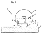
- the measuring device shown in FIG. 1 and designated 11 is used to determine the consistency and / or grain size distribution of a clay strand 1 moving past it in its longitudinal direction and consists essentially of a pin 14 suspended by means of a leaf spring 13 on a holder 12 with low mass Sensor, to which a contactlessly working displacement sensor 15, which is also attached to the holder 12, is assigned to determine the vertical adjustment movements.
- the measuring device 11 is provided with a wheel 16 which is supported on the surface 2 of the clay strand 1 and thus follows, by means of which the reference height of the surface 2 can be determined.
- the wheel 16, which is height-adjustable together with the holder 12 and thus also with the pin 14, is equipped with a rotary pulse generator 17 so that a path-dependent signal can be generated during the adjustment movements of the strand 1.
- the signals emitted by the thin, almost mass-free pin 14, which is rigidly guided in the direction of movement of the clay strand 1 as a sensor, and the rotary encoder 17 of the wheel 16, are subjected to different filter algorithms as profile data of the mechanically scanned surface 2 of the clay strand 1, such that surface waves can be separated into grain fractions and the distribution of the relief heights and / or the peak areas can be calculated.
- the grain size distribution in clay strand 1 can be concluded from the results of this evaluation. If the holder 12 is designed to be movable and, for example, is moved up and down on the wheel axis by an eccentric, then the force on the pin 14 is changed periodically and the consistency can also be inferred from the different sinking depth.
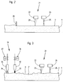
- the size of the grains enclosed in the clay strand 1 can be inferred from the measuring device 21 according to FIG.
- the surface 2 of the sound strand 1 is scanned by a light beam 23 as a sensor and thus without contact.
- the light beam 23 is emitted by a device 22 and the reflections are also detected by this.
- the diameter of the light beam 23 should be in the order of the grain diameter to be resolved, which is to be detected.
- the speed of the strand 1 is measured with the aid of a speed measuring device 24, which operates according to the laser Doppler method and emits and reflects a light beam 25.
- the size of the grains located in the clay strand 1 can be determined on the basis of the signals recorded by the devices 22 and 24.
- the surface 2 of the clay strand 1 is roughened and eroded by means of a scratch finger 26 arranged in front of the measuring device 21 in order to obtain reliable measurement results.
- the measuring device 21 is preceded by a device 31, by means of which a depression 3 can be worked into the surface 2 of the clay string 1 in order to obtain a different profile height, on the other hand, a contactless scanning of the surface 2 by means of a Compressed air jet 33 as a sensor, which emerges from a nozzle 32, possible.
- a contactless scanning of the surface 2 by means of a Compressed air jet 33 as a sensor which emerges from a nozzle 32, possible.
- the measuring device 21 would not be necessary.
- the nozzle 32 is controlled by means of a solenoid valve 34, a periodic application of the surface 2 is therefore easily accomplished.
- a spray nozzle 35 Upstream of the nozzle 32 is a spray nozzle 35, which can also be controlled by means of a solenoid valve 37 and from which a water jet 36 can be ejected for moistening the surface 2 of the clay strand 3.
- the compressed air jet 33 acts on the surface 2 as a compressed air pulse of constant duration in the range of a few tenths of a second, the consistency of the clay strand 1 can be detected.
- the compressed air jet 33 creates a depression which is evaluated together with the distance to the nozzle 32 without being acted upon.
- the measuring device 31 it is also possible to alternately measure the plasticity of the clay strand 1 without water and carry out a grain size analysis with water.
- the spray nozzle 35 is actuated by means of the solenoid valve 37 in a coordinated time sequence with the nozzle 32 emitting the compressed air jet 33.
Landscapes
- Physics & Mathematics (AREA)
- General Physics & Mathematics (AREA)
- Chemical & Material Sciences (AREA)
- Health & Medical Sciences (AREA)
- Life Sciences & Earth Sciences (AREA)
- Analytical Chemistry (AREA)
- Biochemistry (AREA)
- General Health & Medical Sciences (AREA)
- Immunology (AREA)
- Pathology (AREA)
- Dispersion Chemistry (AREA)
- Length Measuring Devices With Unspecified Measuring Means (AREA)
Abstract
Description
Die Erfindung bezieht sich auf ein Verfahren zur Materialanalyse, insbesondere zur Korngrößen- und/oder Konsistensbestimmung eines plastischen oder eines schüttfähigen Gutes, beispielsweise zur Materialanalyse von als Strang ausgeformter keramischer Masse, sowie eine Einrichtung zur Anwendung dieses Verfahrens.The invention relates to a method for material analysis, in particular for determining the grain size and / or consistency of a plastic or a pourable material, for example for material analysis of ceramic mass formed as a strand, and a device for using this method.
Die Bestimmung der Rohstoffparameter eines Gutes wird derzeit nach Labormethoden vorgenommen, in dem z. B. durch Sieben des Materials der Anteil unterschiedlich groß bemessener Körner bestimmt wird. Diese Verfahrensweise ist äußerst arbeitsintensiv und zeitaufwendig und in einem Produktionsprozess nur stichprobenweise anwendbar, eine kontinuierliche Korrektur von Prozeßparametern, gestützt auf diese Art der Materialanalyse, ist demnach nicht realisierbar.The determination of the raw material parameters of a good is currently carried out according to laboratory methods. B. the proportion of different sized grains is determined by sieving the material. This procedure is extremely labor-intensive and time-consuming and can only be used on a random basis in a production process. A continuous correction of process parameters based on this type of material analysis is therefore not feasible.
Aufgabe der Erfindung ist es daher, ein Verfahren sowie eine Einrichtung zur Materialanalyse eines plastischen oder eines schüttfähigen Gutes zu schaffen, mittels denen es möglich ist, kontinuierlich die Korngröße und/oder die Konsistenz des Gute zu bestimmen, so daß bei Abweichungen von den vorgegebenen Werten sofort reagiert werden kann. Der dazu erforderliche Bauaufwand soll gering gehalten werden, auch soll die Handhabung leicht zu bewerkstelligen sein, vor allem aber soll zuverlässig das Oberflächenprofil eines plastischen oder schüttfähigen Gutes, mittels dem auf dessen Korngrößen und/oder die Konsistenz zu schließen ist, erfaßt und ausgewertet werden können.The object of the invention is therefore to provide a method and a device for material analysis of a plastic or a pourable good, by means of which it is possible to continuously determine the grain size and / or the consistency of the good, so that deviations from the specified values can be reacted to immediately. The construction effort required for this should to be kept low, handling should also be easy to accomplish, but above all the surface profile of a plastic or pourable material, by means of which its grain size and / or consistency can be deduced, should be able to be detected and evaluated.
Gemäß der Erfindung ist das Verfahren zur Materialanalyse eines plastischen oder schüttfähigen Gutes dadurch gekennzeichnet, daß das Gut mit seiner Oberfläche relativ zu einer Meßeinrichtung in seiner Längsrichtung bewegt wird, und daß die Oberfläche des Gutes zur Ermittlung eines Oberflächenprofils während der Relativbewegung mit Hilfe eines oder mehrerer der Meßeinrichtung zugeordneter Sensoren mechanisch und/oder berührungslos abgetastet wird.According to the invention, the method for material analysis of a plastic or pourable good is characterized in that the good is moved with its surface relative to a measuring device in its longitudinal direction, and that the surface of the good for determining a surface profile during the relative movement with the help of one or more sensors associated with the measuring device is scanned mechanically and / or without contact.
Das Gut sollte hierbei in seiner Längsrichtung relativ zu der Meßeinrichtung bewegt werden und zur Korngrößenanalyse sollten die hochfrequenten Anteile des an der Meßeinrichtung vorbeigewegten Oberflächenproflls erfaßt werden.The material should be moved in its longitudinal direction relative to the measuring device and the high-frequency components of the surface profile moving past the measuring device should be detected for grain size analysis.
Zweckmäßig ist es, die Oberfläche des plastischen, vorzugsweise als Strang ausgeformten Gutes mit Hilfe eines Stiftes als Sensor abzutasten, der federnd aufgehängt ist, und die vertikalen Verstellbewegungen des in das Gut einsinkender massearm aufgehängten Stiftes bzw. das Relief mittels eines Weggebers, insbesondere eines mit dessen Spitze zusammenwirkenden Wirbelstromweggebers, zu erfassen.It is expedient to scan the surface of the plastic, preferably in the form of a strand, with the aid of a pin as a sensor, which is suspended in a spring-loaded manner, and the vertical adjustment movements of the pin suspended in the material with low mass or the relief by means of a displacement sensor, in particular one with the tip of which cooperates with the eddy current displacement sensor.
Außerdem sollte die Referenzhöhe der Oberfläche des Gutes mit Hilfe eines z.B. sich auf diesem abstützenden vorzugsweise den Sensor tragenden Rades ermittelt werden, wobei mittels des z. B. mit einem Drehimpulsgeber versehenen Rades während der Verstellbewegung des Gutes ein wegabhängiges Signal abgegeben wird.In addition, the reference height of the surface of the goods should be checked using e.g. can be determined on this supporting wheel, preferably carrying the sensor, with the aid of the z. B. provided with a rotary encoder wheel during the adjustment movement of the goods a path-dependent signal.
Nach einer andersartigen Verfahrensweise kann aber auch die Oberfläche des Gutes mit Hilfe eines Lichtstrahls, vorzugsweise einem Laser-Triangulationsweggeber, eines Druckluftstrahles oder eines Ultraschallstrahles als Sensor abgtastet werden.According to a different procedure, the surface of the goods can also be measured with the help of a light beam, preferably a laser triangulation displacement sensor. of a compressed air jet or an ultrasound jet can be scanned as a sensor.
Ferner ist es angezeigt, die Relativgeschwindigkeit des Gutes gegenüber der Meßeinrichtung während der Bewegung zwischen diesen mechanisch und/oder berührungslos zu messen. Dies kann mittels einer Geschwindigkeitsmessung nach dem Laser-Dopplerverfahren durch einen Drehweg- oder Drehgeschwindigkeitsgeber erfolgen.Furthermore, it is advisable to measure the relative speed of the goods relative to the measuring device during the movement between them mechanically and / or without contact. This can be done by means of a speed measurement using the laser Doppler method using a rotary travel or rotary speed sensor.
Das Relief der Oberfläche des Gutes sollte des weiteren in Abhängigkeit von der von der Meßeinrichtung aufgenommenen Geschwindigkeit in ein Längenmaß umgewandelt werden, und die Profildaten der Oberfläche des Gutes sollten unterschiedlichen Filteralgorithen unterzogen werden, derart, daß Oberflächenwellen in Kornfraktionen getrennt und eine Verteilung der Reliefhöhen und/oder der Peakflächen berechnet werden.The relief of the surface of the good should furthermore be converted into a length dimension depending on the speed recorded by the measuring device, and the profile data of the surface of the good should be subjected to different filter algorithms such that surface waves are separated into grain fractions and a distribution of the relief heights and / or the peak areas are calculated.
Angebracht ist es auch, die Oberfläche des Gutes vor dem Abtasten aufzurauhen und/oder zu erodieren. Dies kann durch einen Druckluft-, Dampf-, Oel- oder Wasserstrahl bzw. insbesondere bei einem strangförmig ausgebildeten Gut mittels eines Kratzfingers geschehen. Bei einem als Preßstrang ausgebildeten Gut sollte vor dem berührungslosen Abtasten der Oberfläche die Preßhaut durch ein Abschälmesser, einen Schneidedraht oder dgl. entfernt werden.It is also appropriate to roughen and / or erode the surface of the goods before scanning. This can be done by means of a compressed air, steam, oil or water jet or in particular in the case of a strand-shaped product by means of a scratch finger. In the case of a good formed as a press strand, the press skin should be removed by a peeling knife, a cutting wire or the like before the surface is touchlessly scanned.
Bei Verwendung eines Druckluftstrahles als Sensor sollte die Oberfläche des Gutes vor dem mit Wasser befeuchtet und anschließend durch den Druckluftstrahl aufgerauht oder erodiert werden sollte.When using a compressed air jet as a sensor, the surface of the goods should be moistened with water and then roughened or eroded by the compressed air jet.
Zur Konsistenzbestimmung eines plastischen Gutes ist es angebracht, dessen Oberfläche mit Hilfe eines Druckluftstrahles zu verformen und nach dem Düse-Prallplatte-Prinzip oder mittels eines nach dem Echlolot-Prinzip arbeitenden Ultraschallabstandsensors abzutasten.To determine the consistency of a plastic good, it is appropriate to deform its surface with the aid of a compressed air jet and to scan it according to the nozzle-baffle plate principle or by means of an ultrasonic distance sensor working according to the sonar principle.
Bei einem schüttfähigen Gut sollte dessen Oberfläche vor dem Abtasten durch einen Abstreifer geglättet bzw. auf ein definierten Höhenniveau gebracht werden.In the case of a pourable good, its surface should be smoothed by a scraper or brought to a defined height before scanning.
Ferner ist vorgesehen, den Anpreßdruck des Stiftes bzw. den Druck des Druckluftstrahles auf die Oberfläche des Gutes bei Verwendung eines plastisch verformbaren Werkstoffes in periodischen Zeitabständen zu verändern und die Absenkungsdifferenz der Oberfläche als Maß für die Konsistenz des Werkstoffes zu verwenden, wobei zur Ermittlung der Konsistenz des Werkstoffes die mittlere Tiefe und/oder die Fläche der Absenkung verwertet werden kann. Dabei kann der Stift bzw. der Luftstrahl mit zwei unterschiedlichen Kräften auf die Oberfläche des Gutes einwirken. Auch sollte bei Einwirkung eines Druckluftstrahles als Sensor der Meßeinrichtung auf die Oberfläche eines plastisch verformbaren Gutes wechselweise eine Messung der Konsistenz ohne Wasser und eine Korngrößenanalyse mit vorheriger Befeuchtung vorgenommen werden.It is also provided to change the contact pressure of the pen or the pressure of the compressed air jet onto the surface of the material at periodic intervals when using a plastically deformable material and to use the difference in the lowering of the surface as a measure of the consistency of the material, in order to determine the consistency of the material, the average depth and / or the area of the depression can be used. The pen or the air jet can act on the surface of the material with two different forces. Also, when a compressed air jet acts as a sensor of the measuring device on the surface of a plastically deformable material, a measurement of the consistency without water and a grain size analysis with previous moistening should be carried out alternately.
Die Einrichtung zur Materialanalyse eines plastischen oder eines schüttfähigen Gutes ist gekennzeichnet durch eine vorzugsweise ortsfest angeordnete Meßeinrichtung, gegenüber der das Gut relativ bewegbar ist, und einem oder mehreren der Meßeinrichtung zugeordneten Sensoren, mittels denen die Oberfläche des Gutes während der Relativbewegung mechanisch und/oder berührungslos abtastbar ist und deren vertikale Verstellbewegungen bzw. Reflektionen meßbar sind.The device for material analysis of a plastic or a pourable good is characterized by a preferably stationary measuring device, against which the good is relatively movable, and one or more sensors assigned to the measuring device, by means of which the surface of the good is mechanically and / or contactless during the relative movement is scanned and the vertical adjustment movements or reflections can be measured.
Die Höhen- und Frequenzauflösung des Sensors sollte hierbei im Bereich der Dimensionen der kleinsten aufzulösenden Korngrößen liegen.The height and frequency resolution of the sensor should be in the range of the dimensions of the smallest grain sizes to be resolved.
Der Sensor der Meßeinrichtung kann hierbei durch einen auf der Oberfläche eines strangförmigen Gutes vorzugsweise mit einstellbarer Kraft aufliegenden höhenverstellbar gehaltenen und in Bewegungsrichtung des Gutes geführten massearmen Stift gebildet werden, der an einer vorzugsweise etwa parallel zu dem strangförmigen Gut angeordneten Blattfeder gehalten ist und in Verstellrichtung des Gutes geneigt, vorzugsweise unter einem Winkel von 30 bis 60°, zu diesem an der Blattfeder befestigt sein sollte. Der Stift sollte einen Durchmesser aufweisen, der in der Größenrodnung des mittleren Korngrößenspektrums liegt.In this case, the sensor of the measuring device can be held in a height-adjustable manner and guided in the direction of movement of the good, preferably by an adjustable force, lying on the surface of a strand-like good Low-mass pin are formed, which is held on a preferably arranged approximately parallel to the strand-shaped leaf spring and inclined in the direction of adjustment of the material, preferably at an angle of 30 to 60 °, should be attached to the leaf spring. The pin should have a diameter that corresponds to the size of the medium grain size spectrum.
Zur Ermittlung der vertikalen Verstellbewegung des Stiftes kann diesem ein Weggeber, vorzugsweise ein Wirbelstromweggeber, zugeordnet werden, auch sollte die Meßeinrichtung mit einem Referenzglied z. B. in Form eines auf dem strangförmigen Gut sich abstützenden drehbar gelagerten Rades versehen sein, an dem der Sensor aufgehängt ist, wobei zur Bildung eines in Abhängigkeit von dem Verstellweg des Gutes erzeugbaren Signals das Rad mit einem Drehimpuls- oder Drehgeschwindigkeitsgeber versehen sein sollte.To determine the vertical adjustment movement of the pin, this can be assigned a displacement sensor, preferably an eddy current displacement sensor. The measuring device should also be equipped with a reference element, e.g. B. in the form of a rotatably supported wheel supported on the strand-like material, on which the sensor is suspended, the wheel should be provided with an angular momentum or rotational speed sensor to form a signal that can be generated as a function of the adjustment path of the material.
Nach andersartigen Ausgestaltungen kann der Sensor der Meßeinrichtung durch einen Lichtstrahl, vorzugsweise einen Lasertriangulationswegaufnehmer, einen Druckluftstrahl oder einen Ultraschallstrahl gebildet sein. Bei einem Laser-Lichtstrahl als Sensor sollte dessen Durchmesser in der Größenordnung des mittleren Korngrößenspektrums liegen.According to different configurations, the sensor of the measuring device can be formed by a light beam, preferably a laser triangulation displacement sensor, a compressed air jet or an ultrasound beam. With a laser light beam as a sensor, its diameter should be in the order of the mean grain size spectrum.
Zur Erfassung der Relativgeschwindigkeit des Gutes gegenüber der Meßeinrichtung kann des weiteren ein vorzugsweise nach dem Laserdopplerverfahren wirksamer oder als Drehwinkelgeber ausgebildeter Sensor vorgesehen werden.In order to record the relative speed of the goods relative to the measuring device, a sensor which is preferably effective according to the laser Doppler method or designed as a rotation angle sensor can also be provided.
Zur Aufrauhung und/oder Erodierung der Oberfläche eines strangförmigen Gutes vor dem berührungslosen Abtasten ist es angebracht, einen auf die Oberfläche einwirkenden Druckluft-, Dampf-, Oel- oder Wasserstrahl und/oder einen Kratzfinger vorzusehen oder die Preßhaut eines als Preßstrang ausgebildeten Gutes mittels eines Abschälmesser, einem Schneidedraht oder dgl. zu entfernen.For roughening and / or eroding the surface of a strand-like material before contactless scanning, it is appropriate to provide a compressed air, steam, oil or water jet and / or a scratch finger acting on the surface or the press skin of a good designed as a press strand by means of a Peeling knife, a cutting wire or the like.
Bei einem schüttfähigen Gut sollte vor der Meßeinrichtung ein Abstreifer angeordnet werden.In the case of a pourable good, a scraper should be arranged in front of the measuring device.
Mit Hilfe des erfindungsgemäßen Verfahrens bzw. der vorschlagsgemäß ausgebildeten Einrichtung ist es auf einfache und wirtschaftliche Weise möglich, kontinuierlich die Korngrößen und/oder die Konsistenz eines plastischen oder schüttfähigen Gutes, insbesondere als Strang ausgeformter keramischer Massen, ohne Schwierigkeiten zu bestimmen. Dazu ist lediglich mittels einer in entsprechender Weise ausgebildeten Meßeinrichtung die Oberfläche des Gutes mechanisch und/oder berührungslos abzutasten, um mit Hilfe weiterer leicht ermittelbarer Meßdaten ein Höhenprofil der Oberfläche des Gutes zu erhalten, das Rückschlüsse auf die Steifigkeit des überwachten Gutes und/oder den Anteil der jeweiligen unterschiedlich groß bemessenen Körner erlaubt. Bei Abweichungen von vorgegebenen Daten kann somit sofort in einen Produktionsprozeß eingegriffen werden. Der Bauaufwand, um das erfindungsgemäße Verfahren einsetzen zu können, ist äußerst gering, auch ist dieses ohne Schwierigkeiten in sehr vielseitiger Weise anzuwenden.With the aid of the method according to the invention or the device designed according to the proposal, it is possible in a simple and economical manner to continuously determine the grain sizes and / or the consistency of a plastic or pourable material, in particular as a strand of shaped ceramic masses, without difficulty. For this purpose, the surface of the good is only to be scanned mechanically and / or without contact by means of a correspondingly designed measuring device in order to obtain a height profile of the surface of the good with the aid of further easily determinable measurement data, which allows conclusions to be drawn about the rigidity of the monitored good and / or the proportion of the different sized grains allowed. If there are deviations from the specified data, you can immediately intervene in a production process. The construction cost to be able to use the method according to the invention is extremely low, and it can also be used in a very versatile manner without difficulty.
In der Zeichnung sind drei Ausführungsbeispiele einer Einrichtung zur Materialanalyse eines plastischen Gutes dargestellt, die nachfolgend im einzelnen erläutert sind. Hierbei zeigen, jeweils in schematischer Darstellung:
Figur 1- eine mit einem Stift als Sensor versehene Einrichtung zur Bestimmung der Konsistenz eines Tonstranges,
Figur 2- eine mit einem Lichtstrahl als Sensor arbeitende Einrichtung zur Bestimmung der Konsistenz und/oder Korngrößenverteilung des Tonstranges,
und Figur 3- eine mit einem Druckluft- und Wasserstrahl zur Erosion arbeitende Einrichtung, die der Einrichtung nach
Figur 2 vorgeschaltet ist.
- Figure 1
- a device provided with a pen as a sensor for determining the consistency of a clay strand,
- Figure 2
- a device working with a light beam as a sensor for determining the consistency and / or grain size distribution of the clay strand,
and - Figure 3
- a device working with a compressed air and water jet for erosion, which is connected upstream of the device according to FIG.
Die in Figur 1 dargestellte und mit 11 bezeichnete ortsfest angeordnete Meßeinrichtung dient zur Bestimmung der Konsistenz und/oder Korngrößenverteilung eines an dieser in seiner Längrichtung vorbei bewegten Tonstranges 1 und besteht im wesentlichen aus einem mittels einer Blattfeder 13 an einem Halter 12 massearm aufgehängten Stift 14 als Sensor, dem zur Ermittlung der vertikalen Verstellbewegungen ein ebenfalls an dem Halter 12 angebrachter berührungslos arbeitender Weggeber 15 zugeordnet ist. Außerdem ist die Meßeinrichtung 11 mit einem auf der Oberfläche 2 des Tonstranges 1 sich abstützenden und somit mitlaufenden Rades 16 versehen, mittels dem die Referenzhöhe der Oberfläche 2 bestimmbar ist. Das Rad 16, das zusammen mit dem Halter 12 und somit auch mit dem Stift 14 höhenverstellbar ist, ist mit einem Drehimpulsgeber 17 ausgestattet, so daß während der Verstellbewegungen des Stranges 1 ein wegabhängiges Signal erzeugbar ist.The measuring device shown in FIG. 1 and designated 11 is used to determine the consistency and / or grain size distribution of a
Die von dem durch den dünnen nahezu masselosen Stift 14, der in Bewegungsrichtung des Tonstranges 1 starr geführt ist, als Sensor beeinflußten Weggeber 15 sowie dem Drehimpulsgeber 17 des Rades 16 abgegebenen Signale werden als Profildaten der mechanisch abgetasteten Oberfläche 2 des Tonstranges 1 unterschiedlichen Filteralogarithmen unterzogen, derart, daß Oberflächenwellen in Kornfraktionen getrennt und die Verteilung der Reliefhöhen und/oder der Peakflächen berechnet werden können. Von den Ergebnissen dieser Auswertung kann auf die Korngrößenverteilung in dem Tonstrang 1 geschlossen werden. Wird der Halter 12 beweglich ausgebildet und z.B. durch einen Exzenter auf der Radachse auf- und abbewegt, dann wird damit die Kraft auf den Stift 14 periodisch verändert und aus der unterschiedlichen Einsinktiefe kann ferner auf die Konstistenz geschlosssen werden.The signals emitted by the thin, almost mass-
Mittels der Meßeinrichtung 21 nach Figur 2 ist auf die Größe der in dem Tonstrang 1 eingeschlossenen Körner zu schließen. Um dies zu bewerkstelligen, wird die Oberfläche 2 des Tonstranges 1 durch einen Lichtstrahl 23 als Sensor und somit berührungslos abgetastet. Der Lichtstrahl 23 wird von einem Gerät 22 abgegeben und von diesem werden auch die Reflektionen erfaßt. Der Durchmesser des Lichtstrahles 23 sollte hierbei in der Größenordnung des aufzulösenden Korndurchmessers, der erfaßt werden soll, liegen. Des weiteren wird hierbei die Geschwindigkeit des Stranges 1 mit Hilfe eines Geschwindigkeitsmeßgerätes 24, das nach dem Laser-Dopplerverfahren arbeitet und einen Lichtstrahl 25 aussendet und reflektiert, gemessen. Anhand der von den Geräten 22 und 24 aufgenommenen Signale kann die Größe der in dem Tonstrang 1 befindlichen Körner ermittelt werden.The size of the grains enclosed in the
Mittels eines vor der Meßeinrichtung 21 angeordneten Kratzfingers 26 wird die Oberfläche 2 des Tonstranges 1, um zuverlässige Meßergebnisse zu erhalten, aufgerauht und erodiert.The
Bei der in Figur 3 gezeigten Ausführungsvariante ist der Meßeinrichtung 21 eine Einrichtung 31 vorgeschaltet, mittels der einerseits in die Oberfläche 2 des Tonstranges 1 eine Absenkung 3 eingearbeitet werden kann, um eine abweichende Profilhöhe zu erhalten, andererseits ist ein berührungsloses Abtasten der Oberfläche 2 mittels eines Druckluftstrahles 33 als Sensor, der aus einer Düse 32 austritt, möglich. Bei einer reinen Konsistenzmessung wäre somit die Meßeinrichtung 21 nicht erforderlich. Die Düse 32 wird mittels eines Magnetventils 34 gesteuert, eine periodische Beaufschlagung der Oberfläche 2 ist demnach ohne weiteres zu bewerkstelligen.In the embodiment shown in FIG. 3, the measuring
Der Düse 32 vorgeschaltet ist eine ebenfalls mittels eines Magnetventils 37 steuerbare Spraydüse 35, aus der zum Befeuchten der Oberfläche 2 des Tonstranges 3 ein Wasserstrahl 36 ausgestoßen werden kann.Upstream of the
Mit Hilfe des Druckluftstrahles 33 als Sensor, der als Druckluftimpuls konstanter Dauer im Bereich einiger Zehntel Sekunden auf die Oberfläche 2 einwirkt, kann die Konsistenz des Tonstranges 1 erfaßt werden. Der Druckluftstrahl 33 erzeugt dabei eine Vertiefung, die zusammen mit dem Abstand zur Düse 32 ohne Beaufschlagung ausgewertet wird.With the help of the
Bei der Meßeinrichtung 31 ist es des weiteren möglich, im Wechsel eine Messung der Plastizität des Tonstranges 1 ohne Wasser und eine Korngrößenanalyse mit Wasser vorzunehmen. Dabei wird die Sprühdüse 35 mittels des Magnetventils 37 in abgestimmter Zeitfolge mit der den Druckluftstrahl 33 abgebenden Düse 32 betätigt.With the measuring
Claims (36)
dadurch gekennzeichnet,
daß das Gut (1) mit seiner Oberfläche (2) relativ zu einer vorzugsweise ortsfest angeordneten Meßeinrichtung (11; 21; 31) bewegt wird und daß die Oberfläche (2) des Gutes (1) zur Ermittlung eines Oberflächenprofils während der Relativbewegung mit Hilfe eines oder mehrerer der Meßeinrichtung (11; 21; 31) zugeordneter Sensoren (14; 22; 33) mechanisch und/oder berührungslos abgetastet wird.Method for material analysis, in particular for determining the grain size and / or consistency of a plastic or pourable material, for example for material analysis of ceramic masses formed as a strand,
characterized,
that the material (1) with its surface (2) is moved relative to a preferably stationary measuring device (11; 21; 31) and that the surface (2) of the material (1) for determining a surface profile during the relative movement with the aid of a or several sensors (14; 22; 33) assigned to the measuring device (11; 21; 31) is scanned mechanically and / or without contact.
dadurch gekennzeichnet,
daß das Gut (1) in seiner Längsrichtung relativ zu der Meßeinrichtung (11; 21; 31) bewegt wird.Method according to claim 1,
characterized,
that the good (1) is moved in its longitudinal direction relative to the measuring device (11; 21; 31).
dadurch gekennzeichnet,
daß zur Korngrößenanalyse die hochfrequenten Anteile des an der Meßeinrichtung (11; 21; 31) vorbeibewegten Oberflächenprofils des Gutes (1) erfaßt werden.The method of claim 1 or 2,
characterized,
that the high-frequency components of the surface profile of the material (1) moving past the measuring device (11; 21; 31) are recorded for grain size analysis.
der Ansprüche 1 bis 3,
dadurch gekennzeichnet,
daß die Oberfläche (2) des plastischen, vorzugsweise als Strang ausformten Gutes (1) mit Hilfe eines Stiftes (14) als Sensor abgetastet wird, der federnd aufgehängt ist, und daß die vertikalen Verstellbewegungen des in das Gut (1) einsinkenden, massearm aufgehängten Stiftes (14) mittels eines Weggebers (15), insbesondere eines mit dessen Spitze zusammenwirkenden Wirbelstromweggebers, erfaßt werden.Method according to one or more
of claims 1 to 3,
characterized,
that the surface (2) of the plastic, preferably in the form of a strand (1) is scanned with the aid of a pin (14) as a sensor, which is suspended in a springy manner, and that the vertical adjustment movements of the sinking into the estate (1) are suspended with little mass Pin (14) by means of a displacement sensor (15), in particular an eddy current displacement sensor cooperating with its tip, can be detected.
der Ansprüche 1 bis 4,
dadurch gekennzeichnet,
daß die Referenzhöhe der Oberfläche (2) des Gutes (1) mit Hilfe eines z.B. als sich auf diesem abstützenden vorzugsweise den Sensor tragenden Rades (16) ermittelt wird.Method according to one or more
of claims 1 to 4,
characterized,
that the reference height of the surface (2) of the goods (1) is determined with the aid of a wheel (16), for example, which is preferably supported on the wheel.
dadurch gekennzeichnet,
daß mittels des z.B. mit einem Drehimpulsgeber (17) versehenen Rades (16) während der Verstellbewegung des Gutes (1) ein wegabhängiges Signal abgegeben wird.Method according to claim 5,
characterized,
that a path-dependent signal is emitted by means of the wheel (16) provided, for example, with a rotary pulse generator (17) during the adjustment movement of the material (1).
der Ansprüche 1 bis 3,
dadurch gekennzeichnet
daß die Oberfläche (2) des Gutes (1) mit Hilfe eines Lichtstrahls (23), vorzugsweise einem Laser-Triangulationsweggeber, eines Druckluftstrahles (53) oder eines Ultraschallstrahles als Sensor, abgetastet wird.Method according to one or more
of claims 1 to 3,
characterized
that the surface (2) of the goods (1) is scanned with the aid of a light beam (23), preferably a laser triangulation displacement sensor, a compressed air jet (53) or an ultrasound beam as a sensor.
der Ansprüche 1 bis 7,
dadurch gekennzeichnet,
daß die Relativgeschwindigkeit des Gutes (1) gegenüber der Meßeinrichtung (11; 21; 31) während der Bewegung zwischen diesen mechanisch und/oder berührungslos gemessen wird.Method according to one or more
of claims 1 to 7,
characterized,
that the relative speed of the goods (1) relative to the measuring device (11; 21; 31) during the movement between them mechanically and / or is measured without contact.
dadurch gekennzeichnet,
daß die Relativgeschwindigkeit des Gutes (1) gegenüber der Meßeinrichtung (21) mittels einer Geschwindigkeitsmessung nach dem Laser-Dopplerverfahren durch einen Drehweg- oder Drehgeschwindigkeitsgeber (24, 25) erfaßt wird.A method according to claim 8,
characterized,
that the relative speed of the goods (1) with respect to the measuring device (21) is measured by means of a speed measurement using the laser Doppler method by means of a rotary travel or rotary speed sensor (24, 25).
dadurch gekennzeichnet,
daß das Relief der Oberfläche des Gutes (1) in Abhängigkeit von der von der Meßeinrichtung (11; 21; 31) aufgenommenen Geschwindigkeit in ein Längenmaß umgewandelt wird.Method according to claim 8 or 9,
characterized,
that the relief of the surface of the good (1) is converted into a length dimension as a function of the speed recorded by the measuring device (11; 21; 31).
der Ansprüche 1 bis 10,
dadurch gekennzeichnet,
daß die Profildaten der Oberfläche (2) des Gutes (1) unterschiedlichen Filteralgorithen unterzogen werden, derart, daß Oberflächenwellen in Kornfraktionen getrennt und eine Verteilung der Reliefhöhen und/oder der Peakflächen berechnet werden.Method according to one or more
of claims 1 to 10,
characterized,
that the profile data of the surface (2) of the material (1) are subjected to different filter algorithms in such a way that surface waves are separated into grain fractions and a distribution of the relief heights and / or the peak areas is calculated.
der Ansprüche 1 bis 11,
dadurch gekennzeichnet,
daß die Oberfläche (2) des Gutes (1) vor dem Abtasten aufgerauht und/oder erodiert wird.Method according to one or more
of claims 1 to 11,
characterized,
that the surface (2) of the good (1) is roughened and / or eroded before scanning.
dadurch gekennzeichnet,
daß die Oberfläche (2) des Gutes (1) vor dem Abtasten durch einen Druckluft-, Dampf-, Oel- oder Wasserstrahl bzw. insbesondere bei einem strangförmig ausgeformten Gut (1) mittels eines Kratzfingers (18) aufgerauht oder erodiert wird.Method according to claim 12,
characterized,
that the surface (2) of the material (1) is roughened or eroded by a scratch finger (18) before being scanned by a jet of compressed air, steam, oil or water or, in particular, in the case of a strand-shaped material (1).
dadurch gekennzeichnet,
daß bei einem als Preßstrang ausgebildeten Gut (1) vor dem berührungslosen Abtasten der Oberfläche (2) die Preßhaut durch ein Abschälmesser, einen Schneidedraht oder dgl. entfernt wird.A method according to claim 12 or 13,
characterized,
that in the case of a product (1) designed as a press strand, the press skin is removed by a peeling knife, a cutting wire or the like before the contactless scanning of the surface (2).
der Ansprüche 12 bis 14,
dadurch gekennzeichnet,
daß bei Verwendung eines Druckluftstrahles (33) als Sensor die Oberfläche (2) des Gutes (1) vor dem Abtasten mit Wasser befeuchtet und anschließend durch den Druckluftstrahl (33) aufgerauht oder erodiert wird.Method according to one or more
of claims 12 to 14,
characterized,
that when using a compressed air jet (33) as a sensor the surface (2) of the material (1) is moistened with water before scanning and then roughened or eroded by the compressed air jet (33).
der Ansprüche 12 bis 15,
dadurch gekennzeichnet,
daß zur Konsistenzbestimmung eines plastischen Gutes (1) dessen Oberfläche (2) mit Hilfe eines Druckluftstrahles verformt und nach dem Düse-Prallplatte-Prinzip oder mittels eines nach dem Echolot-Prinzip arbeitenden Ultraschall-Abstandsensors abgetastet wird.Method according to one or more
of claims 12 to 15,
characterized,
that to determine the consistency of a plastic material (1) whose surface (2) is deformed with the aid of a compressed air jet and is scanned according to the nozzle-baffle plate principle or by means of an ultrasound distance sensor working according to the sonar principle.
der Ansprüche 1 bis 11,
gekennzeichnet durch
daß bei einem schuttfähigen Gut dessen Oberfläche vor dem Abtasten durch einen Abstreifer geglättet und/oder auf ein definiertes Höhenniveau gebracht wird.Method according to one or more
of claims 1 to 11,
marked by
that the surface of a debrisable material is smoothed by a scraper and / or brought to a defined height before scanning.
der Ansprüche 1 bis 17,
dadurch gekennzeichnet,
daß der Anpreßdruck des Stiftes (14) bzw. der Druck des Druckluftstrahles (33) auf die Oberfläche (2) des Gutes (1) bei Verwendung eines plastisch verformbaren Werkstoffes in periodischen Zeitabständen verändert und die Absenkungsdifferenz der Oberfläche (2) als Maß für die Konsistenz des Werkstoffes verwendet wird.Method according to one or more
of claims 1 to 17,
characterized,
that the contact pressure of the pin (14) or the pressure of the compressed air jet (33) on the surface (2) of the material (1) changes at periodic intervals when using a plastically deformable material and the Lowering difference of the surface (2) is used as a measure of the consistency of the material.
dadurch gekennzeichnet,
daß zur Ermittlung der Konsistenz des Werkstoffes die mittlere Tiefe und/oder die Fläche der Absenkung verwertet werden.Method according to claim 18,
characterized,
that the mean depth and / or the area of the depression are used to determine the consistency of the material.
dadurch gekennzeichnet,
daß zur Ermittlung der Konsistenz des Werkstoffes der Stift (14) bzw. der Luftstrahl (33) mit zwei unterschiedlichen Kräften auf die Oberfläche (2) des Gutes (1) einwirkt.Method according to claim 18 or 19,
characterized,
that to determine the consistency of the material, the pin (14) or the air jet (33) acts with two different forces on the surface (2) of the material (1).
der Ansprüche 1 bis 20,
dadurch gekennzeichnet,
daß bei Einwirkung eines Druckluftstrahles (33) als Sensor der Meßeinrichtung (31) auf die Oberfläche (2) eines plastisch verformbaren Gutes (1) wechselweise eine Messung der Konsistenz ohne Wasser und eine Korngrößenanalyse mit vorheriger Befeuchtung vorgenommen wird.Method according to one or more
of claims 1 to 20,
characterized,
that when a compressed air jet (33) acts as a sensor of the measuring device (31) on the surface (2) of a plastically deformable material (1), a measurement of the consistency without water and a grain size analysis with previous moistening are carried out alternately.
gekennzeichnet durch
eine vorzugsweise ortsfest angeordnete Meßeinrichtung (11; 21; 31), gegenüber der das Gut (1) relativ bewegbar ist, und einem oder mehreren der Meßeinrichtung (11; 21; 31) zugeordneten Sensoren (14; 23; 33), mittels denen die Oberfläche (2) des Gutes (1) während der Relativbewegung mechanisch und/oder berührungslos abtastbar ist und deren vertikale Verstellbewegungen bzw. Reflektionen meßbar sind.Device for material analysis, in particular for determining the grain size and / or consistency of a plastic or pourable material, for example for material analysis of ceramic masses formed as a strand, for using the method according to claims 1 to 21,
marked by
a preferably stationary measuring device (11; 21; 31), relative to which the good (1) is relatively movable, and one or more sensors (14; 23; 33) assigned to the measuring device (11; 21; 31), by means of which the Surface (2) of the good (1) can be scanned mechanically and / or without contact during the relative movement and its vertical adjustment movements or reflections can be measured.
dadurch gekennzeichnet,
daß die Höhen- und Frequenzauflösung des Sensors (14; 23; 33) im Bereich der Dimensionen der kleinsten aufzulösenden Korngrößen liegt.Device according to claim 22,
characterized,
that the height and frequency resolution of the sensor (14; 23; 33) is in the range of the dimensions of the smallest grain sizes to be resolved.
dadurch gekennzeichnet,
daß der Sensor der Meßeinrichtung (11) durch einen auf der Oberfläche (2) eines strangförmigen Gutes (1) vorzugsweise mit einstellbarer Kraft aufliegenden höhenverstellbar gehaltenen und in Bewegungsrichtung des Gutes (1) geführten massearmen Stift (14) gebildet ist.Device according to claim 22 or 23,
characterized,
that the sensor of the measuring device (11) is formed by a low-mass pin (14) which is held on the surface (2) of a strand-like good (1) and is preferably adjustable with an adjustable force and is guided in the direction of movement of the good (1).
dadurch gekennzeichnet,
daß der Stift (14) an einer vorzugsweise etwa parallel zu dem strangförmigen Gut (1) angeordneten Blattfeder (12) gehalten ist.Device according to claim 24,
characterized,
that the pin (14) on a preferably approximately parallel to the strand-shaped Well (1) arranged leaf spring (12) is held.
dadurch gekennzeichnet,
daß der Stift (14) in Verstellrichtung des Gutes (1) geneigt, vorzugsweise unter einem Winkel von 30 bis 60° , zu diesem an der Blattfeder (12) befestigt ist.Device according to claim 24 or 25,
characterized,
that the pin (14) inclined in the direction of adjustment of the goods (1), preferably at an angle of 30 to 60 °, is attached to the leaf spring (12).
der Ansprüche 24 bis 26,
dadurch gekennzeichnet,
daß der Stift (14) einen Durchmesser aufweist, der in der Größenordnung des mittleren Korngrößenspektrums liegt.Setup after one or more
of claims 24 to 26,
characterized,
that the pin (14) has a diameter which is in the order of the average grain size spectrum.
der Ansprüche 24 bis 27,
dadurch gekennzeichnet,
daß zur Ermittlung der vertikalen Verstellbewegung des Stiftes (14) diesem ein Weggeber (15), vorzugsweise ein Wirbelstromweggeber, zugeordnet ist.Setup after one or more
of claims 24 to 27,
characterized,
that a displacement sensor (15), preferably an eddy current displacement sensor, is assigned to determine the vertical adjustment movement of the pin (14).
der Ansprüche 22 bis 28,
dadurch gekennzeichnet,
daß die Meßeinrichtung (11) mit einem Referenzglied z.B. in Form eines auf dem strangförmigen Gut (1) sich abstützenden drehbar gelagerten Rades (16) versehen ist, an dem der Sensor (14) aufgehängt ist.Setup after one or more
of claims 22 to 28,
characterized,
that the measuring device (11) with a reference element, for example in the form of a the strand-like material (1) which is supported on a rotatably mounted wheel (16) on which the sensor (14) is suspended.
dadurch gekennzeichnet,
daß zur Bildung eines in Abhängigkeit von dem Verstellweg des Gutes (1) erzeugbaren Signals das Rad (16) mit einem Drehimpuls- oder Drehgeschwindigkeitsgeber (17) versehen ist.Device according to claim 29,
characterized,
that the wheel (16) is provided with an angular momentum or rotational speed sensor (17) to form a signal which can be generated as a function of the adjustment path of the material (1).
dadurch gekennzeichnet,
daß der Sensor der Meßeinrichtung (21; 31) durch einen Lichtstrahl (23), vorzugsweise einen Lasertriangulationswegaufnehmer, einen Druckluftstrahl (33) oder einen Ultraschallstrahl gebildet ist.Device according to claim 22 or 23,
characterized,
that the sensor of the measuring device (21; 31) is formed by a light beam (23), preferably a laser triangulation displacement sensor, a compressed air jet (33) or an ultrasound beam.
dadurch gekennzeichnet,
daß bei einem Laser-Lichtstrahl (23) als Sensor dessen Durchmesser in der Größenordnung des mittleren Korngrößenspektrums liegt.Device according to claim 31,
characterized,
that with a laser light beam (23) as a sensor, its diameter is in the order of the mean grain size spectrum.
der Ansprüche 22 bis 32,
dadurch gekennzeichnet,
daß zur Erfassung der Relativgeschwindigkeit des Gutes (1) gegenüber der Meßeinrichtung (21) ein vorzugsweise nach dem Laserdopplerverfahren wirksamer oder als Drehwinkelgeber ausgebildeter Sensoren (24, 25) vorgesehen ist.Setup after one or more
of claims 22 to 32,
characterized,
that a sensor (24, 25), which is preferably effective according to the laser Doppler method or is designed as a rotary angle sensor, is provided for detecting the relative speed of the goods (1) relative to the measuring device (21).
der Ansprüche 22 bis 33,
dadurch gekennzeichnet,
daß zur Aufrauhung und/oder Erodierung der Oberfläche (2) eines strangförmigen Gutes (1) vor dem Abtasten ein auf die Oberfläche (2) einwirkender Druckluft-, Dampf-, Oel- oder Wasserstrahl und/oder ein Kratzfinger (26) vorgesehen sind.Setup after one or more
of claims 22 to 33,
characterized,
that for roughening and / or eroding the surface (2) of a strand-like material (1) before scanning, a compressed air, steam, oil or water jet and / or a scratch finger (26) acting on the surface (2) are provided.
der Ansprüche 22 bis 34,
dadurch gekennzeichnet,
daß die Preßhaut eines als Preßstrang ausgebildeten Gutes (1) mittels eines Abschälmessers, einem Schneidedraht oder dgl. entfernbar ist.Setup after one or more
of claims 22 to 34,
characterized,
that the press skin of a product (1) designed as a press strand can be removed by means of a peeling knife, a cutting wire or the like.
der Ansprüche 22 bis 34
dadurch gekennzeichnet,
daß bei einem schüttfähigen Gut vor der Meßeinrichtung ein Abstreifer angeordnet ist.Setup after one or more
of claims 22 to 34
characterized,
that a wiper is arranged in front of the measuring device for a pourable material.
Applications Claiming Priority (2)
| Application Number | Priority Date | Filing Date | Title |
|---|---|---|---|
| DE19532547 | 1995-09-04 | ||
| DE1995132547 DE19532547A1 (en) | 1995-09-04 | 1995-09-04 | Method and device for material analysis |
Publications (2)
| Publication Number | Publication Date |
|---|---|
| EP0762076A2 true EP0762076A2 (en) | 1997-03-12 |
| EP0762076A3 EP0762076A3 (en) | 1997-10-08 |
Family
ID=7771178
Family Applications (1)
| Application Number | Title | Priority Date | Filing Date |
|---|---|---|---|
| EP96111340A Withdrawn EP0762076A3 (en) | 1995-09-04 | 1996-07-13 | Method and apparatus for material analysis |
Country Status (2)
| Country | Link |
|---|---|
| EP (1) | EP0762076A3 (en) |
| DE (1) | DE19532547A1 (en) |
Families Citing this family (1)
| Publication number | Priority date | Publication date | Assignee | Title |
|---|---|---|---|---|
| DE19959198A1 (en) * | 1999-12-08 | 2001-06-13 | Abb Patent Gmbh | Device for detecting surface quality of material transported on conveyor subjects surface of material to pressurized gas, detects/assesses surface quality of resulting local surface deformations |
Family Cites Families (4)
| Publication number | Priority date | Publication date | Assignee | Title |
|---|---|---|---|---|
| FR2041432A5 (en) * | 1969-04-24 | 1971-01-29 | Polysius Gmbh | Grain size distribution determination for a - ground material |
| GB1318701A (en) * | 1970-01-30 | 1973-05-31 | Rank Organisation Ltd | Methods of waveform analysis and apparatus therefor |
| DE3412615C2 (en) * | 1984-04-04 | 1986-07-24 | Fraunhofer-Gesellschaft zur Förderung der angewandten Forschung e.V., 8000 München | Method for determining the grain size in a polycrystalline material |
| DE3929172A1 (en) * | 1989-09-02 | 1991-03-07 | Bayer Ag | DEVICE FOR DETERMINING THE SIZE DISTRIBUTION OF PIGMENT BEADS IN A LACQUER SURFACE |
-
1995
- 1995-09-04 DE DE1995132547 patent/DE19532547A1/en not_active Withdrawn
-
1996
- 1996-07-13 EP EP96111340A patent/EP0762076A3/en not_active Withdrawn
Non-Patent Citations (1)
| Title |
|---|
| None |
Also Published As
| Publication number | Publication date |
|---|---|
| EP0762076A3 (en) | 1997-10-08 |
| DE19532547A1 (en) | 1997-03-06 |
Similar Documents
| Publication | Publication Date | Title |
|---|---|---|
| EP1990204B1 (en) | Process and device for coating a surface | |
| DE4134265C2 (en) | Device and method for producing a three-dimensional object by means of stereography | |
| EP0494430B1 (en) | Method for measuring the diameter of cylinders, particularly of drums | |
| EP2106530A1 (en) | Method and device for sensing the three-dimensional surface of an object, in particular of a vehicle tire | |
| DE3713279A1 (en) | METHOD FOR DETECTING DIMENSIONAL ERRORS | |
| AT506313B1 (en) | BENDING BENCH FOR A BENDING PEPPER, IN PARTICULAR BUTTING PRESSURE | |
| DE10224635A1 (en) | Method and device for determining the eccentricity of a hollow block | |
| EP0706841A1 (en) | Method and device for adjusting cleaning rolls for cleaning the rolls in rolling stands | |
| DE68922914T2 (en) | Device for cutting the layer of bacon and / or fat from meat. | |
| DE69409748T2 (en) | Device and method for measuring the shape and / or flatness of a moving material | |
| DE4139697C2 (en) | Device for testing and measuring mattresses, upholstery or similar flat-elastic objects | |
| EP0762076A2 (en) | Method and apparatus for material analysis | |
| DE4138837A1 (en) | DEVICE FOR CUTTING A TEXTILE TRACK, IN PARTICULAR. A LABEL OF LABELS | |
| DE4422691A1 (en) | High pressure water jet cutter | |
| EP0976509A3 (en) | Method and apparatus for slitting web material | |
| DE3841177C2 (en) | ||
| EP1919659B1 (en) | Measuring station for a pipe cutting machine | |
| DE10063786A1 (en) | Device and method for measuring an object | |
| DE4300290A1 (en) | ||
| EP0757788B1 (en) | Process and device for detecting structural faults of moving flat textile materials | |
| EP2865998A1 (en) | Material measure for incremental encoder and method for its manufacture | |
| DE10023127B4 (en) | Method for operating a scanning device for optical density measurement | |
| DE3705763C2 (en) | ||
| EP0402779B1 (en) | Method and device for determining surface structures | |
| DE3814697C2 (en) |
Legal Events
| Date | Code | Title | Description |
|---|---|---|---|
| PUAI | Public reference made under article 153(3) epc to a published international application that has entered the european phase |
Free format text: ORIGINAL CODE: 0009012 |
|
| AK | Designated contracting states |
Kind code of ref document: A2 Designated state(s): DE FR GB IT |
|
| PUAL | Search report despatched |
Free format text: ORIGINAL CODE: 0009013 |
|
| AK | Designated contracting states |
Kind code of ref document: A3 Designated state(s): DE FR GB IT |
|
| 17P | Request for examination filed |
Effective date: 19971011 |
|
| 17Q | First examination report despatched |
Effective date: 19990706 |
|
| STAA | Information on the status of an ep patent application or granted ep patent |
Free format text: STATUS: THE APPLICATION HAS BEEN WITHDRAWN |
|
| 18W | Application withdrawn |
Withdrawal date: 19991113 |