EP0762002B1 - Bolzen-typ Synchronisiereinheit - Google Patents
Bolzen-typ Synchronisiereinheit Download PDFInfo
- Publication number
- EP0762002B1 EP0762002B1 EP96110102A EP96110102A EP0762002B1 EP 0762002 B1 EP0762002 B1 EP 0762002B1 EP 96110102 A EP96110102 A EP 96110102A EP 96110102 A EP96110102 A EP 96110102A EP 0762002 B1 EP0762002 B1 EP 0762002B1
- Authority
- EP
- European Patent Office
- Prior art keywords
- outer diameter
- pin
- assembly
- synchronizer
- diameter portion
- Prior art date
- Legal status (The legal status is an assumption and is not a legal conclusion. Google has not performed a legal analysis and makes no representation as to the accuracy of the status listed.)
- Expired - Lifetime
Links
- 230000000712 assembly Effects 0.000 claims description 63
- 238000000429 assembly Methods 0.000 claims description 63
- 230000000295 complement effect Effects 0.000 claims description 12
- 238000006073 displacement reaction Methods 0.000 claims description 5
- 230000006835 compression Effects 0.000 claims 1
- 238000007906 compression Methods 0.000 claims 1
- 230000005540 biological transmission Effects 0.000 description 19
- 230000001360 synchronised effect Effects 0.000 description 6
- 230000000977 initiatory effect Effects 0.000 description 4
- 230000007935 neutral effect Effects 0.000 description 2
- 230000004323 axial length Effects 0.000 description 1
- 230000008859 change Effects 0.000 description 1
- 150000001875 compounds Chemical class 0.000 description 1
- 230000008676 import Effects 0.000 description 1
- 230000006872 improvement Effects 0.000 description 1
- 230000003993 interaction Effects 0.000 description 1
- 230000007246 mechanism Effects 0.000 description 1
- 230000009467 reduction Effects 0.000 description 1
- 238000000926 separation method Methods 0.000 description 1
Images


Classifications
-
- F—MECHANICAL ENGINEERING; LIGHTING; HEATING; WEAPONS; BLASTING
- F16—ENGINEERING ELEMENTS AND UNITS; GENERAL MEASURES FOR PRODUCING AND MAINTAINING EFFECTIVE FUNCTIONING OF MACHINES OR INSTALLATIONS; THERMAL INSULATION IN GENERAL
- F16D—COUPLINGS FOR TRANSMITTING ROTATION; CLUTCHES; BRAKES
- F16D23/00—Details of mechanically-actuated clutches not specific for one distinct type
- F16D23/02—Arrangements for synchronisation, also for power-operated clutches
- F16D23/04—Arrangements for synchronisation, also for power-operated clutches with an additional friction clutch
- F16D23/06—Arrangements for synchronisation, also for power-operated clutches with an additional friction clutch and a blocking mechanism preventing the engagement of the main clutch prior to synchronisation
- F16D23/0606—Arrangements for synchronisation, also for power-operated clutches with an additional friction clutch and a blocking mechanism preventing the engagement of the main clutch prior to synchronisation the blocking mechanism comprising an axially-extending shouldered pin passing through a hole in a radial wall
-
- F—MECHANICAL ENGINEERING; LIGHTING; HEATING; WEAPONS; BLASTING
- F16—ENGINEERING ELEMENTS AND UNITS; GENERAL MEASURES FOR PRODUCING AND MAINTAINING EFFECTIVE FUNCTIONING OF MACHINES OR INSTALLATIONS; THERMAL INSULATION IN GENERAL
- F16D—COUPLINGS FOR TRANSMITTING ROTATION; CLUTCHES; BRAKES
- F16D23/00—Details of mechanically-actuated clutches not specific for one distinct type
- F16D23/02—Arrangements for synchronisation, also for power-operated clutches
- F16D23/04—Arrangements for synchronisation, also for power-operated clutches with an additional friction clutch
- F16D23/06—Arrangements for synchronisation, also for power-operated clutches with an additional friction clutch and a blocking mechanism preventing the engagement of the main clutch prior to synchronisation
- F16D2023/065—Means to provide additional axial force for self-energising, e.g. by using torque from the friction clutch
-
- F—MECHANICAL ENGINEERING; LIGHTING; HEATING; WEAPONS; BLASTING
- F16—ENGINEERING ELEMENTS AND UNITS; GENERAL MEASURES FOR PRODUCING AND MAINTAINING EFFECTIVE FUNCTIONING OF MACHINES OR INSTALLATIONS; THERMAL INSULATION IN GENERAL
- F16H—GEARING
- F16H61/00—Control functions within control units of change-speed- or reversing-gearings for conveying rotary motion ; Control of exclusively fluid gearing, friction gearing, gearings with endless flexible members or other particular types of gearing
- F16H61/70—Control functions within control units of change-speed- or reversing-gearings for conveying rotary motion ; Control of exclusively fluid gearing, friction gearing, gearings with endless flexible members or other particular types of gearing specially adapted for change-speed gearing in group arrangement, i.e. with separate change-speed gear trains arranged in series, e.g. range or overdrive-type gearing arrangements
-
- Y—GENERAL TAGGING OF NEW TECHNOLOGICAL DEVELOPMENTS; GENERAL TAGGING OF CROSS-SECTIONAL TECHNOLOGIES SPANNING OVER SEVERAL SECTIONS OF THE IPC; TECHNICAL SUBJECTS COVERED BY FORMER USPC CROSS-REFERENCE ART COLLECTIONS [XRACs] AND DIGESTS
- Y10—TECHNICAL SUBJECTS COVERED BY FORMER USPC
- Y10T—TECHNICAL SUBJECTS COVERED BY FORMER US CLASSIFICATION
- Y10T74/00—Machine element or mechanism
- Y10T74/19—Gearing
- Y10T74/19219—Interchangeably locked
- Y10T74/19284—Meshing assisters
Definitions
- the present invention relates to pin-type synchronizer assemblies and synchronizer pin assemblies therefor.
- the present invention relates to pin-type synchronizer assemblies utilizing synchronizer pin assemblies having a large diameter portion, a small diameter and an intermediate diameter portion interposed between the large and small diameter portions, the large diameter portion interacting with apertures in a sliding clutch plate to define baulking means and being axially movable relative to and resiliently biased away from the synchronizer ring associated therewith.
- the synchronizer assemblies may be subject to improvement by providing an assembly which eliminates the use of cantilevered pins and/or separate spring pins, spring-biased plungers and/or other pre-energizing devices.
- British Patent No. 1,210,808 discloses a double-acting pin-type synchronizer assembly utilizing synchronizer pin assemblies having a large diameter baulking portion and a small diameter portion, the large diameter portion being axially movable and resiliently biased away from its associated synchronizer ring. While eliminating the need for separate pre-energizing means, the disclosed device does not prevent crash shifts if after initiating engagement of a target ratio, the operator attempted to reengage a previously engaged ratio.
- an improved synchronizer pin assembly and double-acting pin-type synchronizer assembly utilizing same is provided wherein the synchronizer pin assemblies are mounted to synchronizer rings at each end thereof, the requirement for separate pre-energizing devices such as spring pins and/or spring-biased plungers or the like is eliminated, and crash shifts into a previously engaged ratio after initiation of engagement into a target ratio are positively prevented.
- each set of pins includes a plurality of generally equally circumferentially spaced synchronizer pin assemblies, each having a large diameter portion, a small diameter portion and an interposed intermediate diameter portion.
- the large diameter portions of the pin assemblies interact with apertures in a sliding clutch plate to define baulking means and are axially movable relative to and resiliently biased away from the synchronizer rings associated therewith.
- the apertures and pin assemblies are configured to assure that, at initial engagement between the baulking ramps defined by the large diameter portions and the periphery of their associated apertures in the clutch plate, the apertures and large diameter portions are not in register whereby continued axial movement of the clutch plate toward a synchronizer ring will cause axial movement of the large diameter pin assembly portions against the bias to resiliently urge the synchronizer ring into frictional engagement with the associated conical surface on the gear being engaged to properly pre-energize the synchronizer by causing the synchronizer assembly to tend to rotate, or clock, with the gear being engaged.
- the pin assemblies and clutch plate apertures are further configured such that as the clutch plate moves from disengaging one of the gears to neutral or toward engaging the other gear, it will pass through a position whereat the apertures therein will engage and/or axially displace the intermediate diameter portions of both sets of pin assemblies whereby the apertures are positively held out of register with the large diameter portions of both sets of pin assemblies and axial movement of the clutch plate in either direction will result in an axial movement of the associated large diameter portions against the bias force and desired pre-energizing.
- a new and improved pin-type synchronizer assembly and a synchronizer pin assembly therefor is provided which minimizes cantilevered synchronizer pin mounting, eliminates the requirement for separate pre-energizing devices and, upon initiation of engagement of a target gear ratio, will positively prevent crash shifts if engagement of the previously engaged ratio is attempted.
- Figure 1 is a schematic illustration of a change-gear transmission utilizing the pin-type synchronizer assembly of the present invention.
- Figure 2 is a schematic illustration of the shift pattern for the transmission of Figure 1.
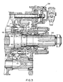
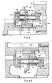
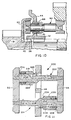
- Figure 3 is an enlarged sectional view of a portion of the transmission of Figure 1 illustrating the pin-type synchronizer assembly of the present invention.
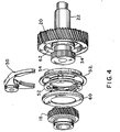
- Figure 4 is an exploded view of the double-acting pin-type synchronizer assembly of the present invention, as used in the transmission of Figure 1.
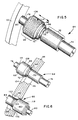
- Figure 5 is a perspective view illustrating the synchronizer pin assembly structure of the present invention.
- Figure 6 is a perspective view illustrating the relationship between the two sets of synchronizer pin assemblies and the sliding clutch plate apertures associated therewith.
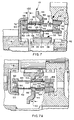
- Figures 7, 7A, 8, 8A, 9, 9A and 10 are partial sectional views illustrating a sequence of synchronizer assembly operation during engagement of the direct ratio.
- Figure 11 is a schematic illustration of an alternate embodiment of the present invention.
- Figure 12 is a schematic illustration of a further alternate embodiment of the present invention.
- a change-gear transmission advantageously utilizing the double-acting pin-type synchronizer assembly 10 of the present invention may be seen by reference to Figs. 1, 2 and 3.
- Synchronized jaw clutch assemblies for use in change-gear transmissions, usually vehicular change-gear transmissions, are well known in the prior art and examples thereof may be seen by reference to U.S. Patents No. 3,548,983; 4,059,178 and 4,540,074.
- Pin-type synchronizers also known as "Clark-type" synchronizers, also are well known in the prior art, as may be seen by reference to U.S. Patents No. 3,910,390 and 4,018,319.
- Transmission 12 includes a main transmission section 14 connected in series with a range-type auxiliary transmission section 16 and utilizes double-acting, pin-type range synchronizer assembly 10 to clutch either gear 18 or gear 20 to output shaft 22.
- the shift pattern for transmission 12 is schematically illustrated in Fig. 2.
- transmission 12 has a "repeat-H" type of control wherein the operator's use of a range switch (not shown) will cause an automatic shifting of the range clutch by means of a two-position piston actuator 28 controlling the axial position of a shift yoke 30. Transmissions of this general type are well known in the prior art.
- the invention is also applicable to transmissions having a combined range- and splitter-type auxiliary section, such as those marketed by Eaton Corporation under the trademark "Super-10" and may be seen in greater detail by reference to aforementioned U.S. Patents No. 4,944,197 and 5,231,895.
- the pin-type synchronizer assembly of the present invention includes an axially slidable clutch collar member 32 that is mounted for axial movement relative to and rotational movement with an externally splined portion 34 of the output shaft 22.
- the clutch collar is provided with jaw clutch teeth 36 and 38, which are adapted to be disposed in axial engagement with complementary jaw clutch teeth 40 and 42, respectively, formed on gears 18 and 20, respectively, for positively clutching a selected one of the gears to the output shaft 22.
- the clutch collar member includes a radially extending flange or plate member 44 having a plurality of circumferentially spaced openings or apertures therethrough which are parallel to the shaft.
- the apertures through sliding clutch collar plate 44 are grouped into a first set of generally equally circumferentially spaced apertures 46 and a second set of generally equally circumferentially spaced apertures 48, the two sets of which are offset in a predetermined manner.
- a plurality of synchronizer pin assemblies 50 Disposed through the apertures in the plate 44 are a plurality of synchronizer pin assemblies 50, which are fixed at each of their ends to a synchronizer ring 52 and 54, respectively, defining a conical friction surface for cooperation with a corresponding conical friction surface 56 and 58, respectively, associated with the gears 18 and 20, respectively.
- friction surface 56 is defined by a cup member 60 affixed to gear 18, while friction surface 58 is formed directly on an inner diameter surface 62 of gear. 20.
- the synchronizer pin assemblies define a first set of synchronizer pins 64 and a second set of synchronizer pins 66, each set being generally equally circumferentially spaced in a manner corresponding to the circumferential spacing of the sets of apertures and the sets of pins being offset from one another, in a manner corresponding to the offset between the sets of apertures.
- the synchronizer rings 52 and 54 and the associated gear-mounted complementary conical surfaces 56 and 58, respectively, are intended to frictionally engage and cause the target gear and shaft 22 to rotate at substantially synchronous speeds and further to engage, prior to or during engagement of the baulking surfaces on the sliding clutch plate and associated synchronizer pin assemblies, to pre-energize the synchronizer assembly by causing synchronizer ring and synchronizer pin assembly to tend to rotate or "clock" with the target gear.
- pre-energizing there should be some means to assure that the conical friction surfaces of the synchronizer ring and the target gear ratio are brought into at least light frictional contact prior to or during the baulking surfaces' initial engagement, which is commonly referred to as "pre-energizing" of a synchronizer.
- pre-energizing was accomplished by means of pre-energizing devices separate from the synchronizer pin assembly, which devices usually comprised spring pins, spring-biased plunger members and the like.
- the synchronizer rings 52 and 54 are connected to the synchronizer pin assemblies 64 and 66, the synchronizer pin assemblies 64 being a first set of three assemblies and the assemblies 66 being a second set of three assemblies.
- assemblies 64 are equally spaced circumferentially around the synchronizer rings 52 and 54 in known manner, as are assemblies 66 in the second set of assemblies, but the two sets of pin assemblies 64 and 66 are circumferentially offset relative to each other in a manner corresponding to the circumferential offset of the apertures 46 and 48 in the clutch plate 44, as is known in the art.
- Each of the spring pin assemblies 64 includes a large diameter portion 68, a small diameter portion 70, and an intermediate diameter portion 72 interposed the large and small diameter portions.
- Reduced diameter peg portion 74 extends axially rightwardly from the small diameter portion 70 for receipt within aperture 76 provided in synchronizer ring 54, and a similar reduced diameter peg portion 78 extends axially leftwardly from the enlarged diameter portion 68 for receipt within aperture 80 provided in synchronizer ring 52.
- the peg portions 74 and 78 are received within the apertures 76 and 80, respectively, in a press-fit/staked relationship.
- Synchronizer pin assemblies 66 are substantially functionally and structurally identical to synchronizer pin assemblies 64 but are oriented in an opposite manner relative to the synchronizer rings.
- synchronizer pin assembly 66 comprises a large diameter portion 82, a small diameter portion 84, and an intermediate diameter portion 86 interposed the large and small diameter portions.
- Reduced diameter peg portions 88 and 90, respectively, are provided for press-fit/staked receipt within apertures 92 and 94, respectively, provided in the synchronizer ring 54 and 52, respectively.
- ramped surfaces 96 and 98 extend between the enlarged diameter outer surface and the intermediate diameter outer surface, and the intermediate diameter surface and the small diameter surface 70 of pin assembly 64, respectively, while on assembly 66, ramped, inclined surfaces 100 and 102, respectively, extend from the enlarged diameter outer surface to the intermediate diameter outer surface, and the intermediate diameter surface and the small diameter surface, respectively.
- the leftward end of aperture 46 and the rightward end of aperture 48 in the clutch collar plate 44, respectively, are provided with radially outwardly extending ramped surfaces 104 and 106, respectively, for interaction with the ramped surfaces 96 and 100, respectively.
- Ramps 104 at the leftward ends of apertures 46 through clutch plate 44 and ramps 96 of the synchronizer pin assemblies 64 provide the baulking ramp function for engagement of gear 18 in the known manner for pin-type synchronizers
- ramps 106 at the rightward end of apertures 48 through the clutch plate 44 and ramps 100 on the synchronizer pins 66 provide the baulking ramp function for engagement of gear 20 in the known manner for pin-type synchronizer assemblies.
- a shoulder 113 limits the rightward axial travel of collar 108, while a resilient biasing means, such as coil spring 114 seated on synchronizer ring 52, resiliently biases the collar 108 rightwardly against the stop 113.
- the outer diameter surfaces of enlarged diameter portion 82, intermediate diameter portion 86, ramp 100 and ramp 102 of synchronizer pin assembly 66 are defined by the outer diameter surface of a collar or sleeve 116 axially slidable on the outer diameter surface 118 of a shaft portion 120 of the assembly 66.
- a shoulder 122 limits leftward axial travel of the sleeve 116, and a coil spring 124 extending between the synchronizer ring 54 and a spring seat 126 defined by the collar 116 resiliently biases the collar 116 leftwardly against the shoulder 122.
- the synchronizer pin and ring assembly 128 is not free to rotate sufficiently to circumferentially align the intermediate diameter portions 86 of the spring pin assemblies 66 with apertures 48 and clutch plate 44 or to circumferentially align the apertures 48 with the large diameter portion 82 of the spring pin assemblies 66.
- the large diameter portions 68 and 82 of spring pin assemblies 64 and 66, respectively are of a diameter generally equal to the diameter of apertures 46 and 48, respectively, through the clutch plate 44.
- the synchronizer pin and ring assembly 128 has limited rotational freedom relative to the clutch plate 44 and cannot rotate sufficiently relative thereto to align either the intermediate diameter portion 86 or large diameter portion 82 of spring pin assemblies 66 with aperture 48.
- pin-type synchronizer assembly 10 of the present invention is illustrated in sequential form by reference to Figs. 7-7A, 8-8A, 9-9A and 10.
- the sequence illustrated is that of disengaging range reduction gear 20 from output shaft 22 and engaging range direct gear 18 to the output shaft 22. It is noted that for a range-type, synchronized, double-acting clutch assembly operated by a two-position piston actuator 28, the assembly will not be intentionally positioned or dwell in an intermediate or neutral position.
- sleeve 108 In the non-displaced position of sleeve 108, sleeve 108 has a clearance 132 for leftward movement of about 2.2 mm - 3,2 mm (.090-.125 inch), which is greater than the axial distance 130. Further axial movement of the clutch 32 leftwardly toward gear 18, thus, will result in resilient axial displacement of collar 108, which will result in bringing the synchronizer ring 52 into frictional engagement with inner conical surface 56 defined by cup 60 carried by gear 18.
- Figs. 8-8A the sliding clutch 32 has been moved leftwardly from the position shown in Figs. 7-7A sufficiently to cause aperture set 48 to axially clear the large diameter portions 82 of the synchronizer pin set 66 and further to resiliently axially leftwardly displace the collar 108 of the synchronizer pin set 64, resulting in the synchronizer ring and synchronizer pin assembly 128 being pre-energized to tend to rotate with gear 18, which, due to the assumed non-synchronous rotation therebetween, causes the baulking surfaces to be urged into contact, preventing further leftward axial movement of the clutch 32 and applying a frictional force between surfaces 56 and 52 to tend to cause the gear 18 and shaft 22 to rotate at substantially the same speed.
- a pin-type synchronizer assembly 200 utilizes synchronizer rings 52 and 54 and a clutch collar plate 44 substantially structurally and functionally identical to the synchronizer ring and clutch plate described above in reference to the synchronizer assemblies 10 illustrated in Figs. 5-10.
- Embodiment 200 differs in that the spring pin assemblies 202 and 204 each comprises shaft portions 206 and 208, respectively, which define the small diameter portions and intermediate diameter portions 210 and 212, 214 and 216, respectively, thereof.
- the function and operation of synchronizer assembly 200 is substantially identical to the operation of pin-type synchronizer assembly 10 described above.
- Pin-type synchronizer assembly 250 includes synchronizer rings 52 and 54 and clutch plate 44 having aperture 46 therein, all of which are structurally and functionally substantially identical to the synchronizer rings and clutch plate described above in connection with synchronizer assembly 10.
- Pin-type synchronizer assembly 250 utilizes a synchronizer pin assembly 260 comprising a single substantially constant diameter shaft 262, which is received in apertures 76 and 80 in the synchronizer rings 50 and 52, respectively, preferably in a press-fit/staked relationship.
- Axially slidable on the outer diameter of shaft 262 is a collar 264 having an outer diameter surface defining a large diameter surface 266, a small diameter surface 268, an intermediate diameter surface 270, ramp 272 between surfaces 268 and 270, and ramp 274 between surfaces 270 and 266.
- Sleeve 262 is of a shorter axial distance than the separation between the synchronizer rings 52 and 54, and is resiliently biased by a spring 276 axially away from the synchronizer ring 52 associated therewith.
- the function and operation of synchronizer 250 and of synchronizer pin assemblies 260 associated therewith is identical to that of the synchronizer assembly 10 described above.
Landscapes
- Engineering & Computer Science (AREA)
- General Engineering & Computer Science (AREA)
- Mechanical Engineering (AREA)
- Mechanical Operated Clutches (AREA)
- Structure Of Transmissions (AREA)
Claims (18)
- Synchronisieranordnung (10;200;250) in der Bauart mit Zapfen, zu der gehören:eine Zapfenmittelanordnung (64,66;202,204;260),ein erster Synchronring (52,54),eine Kupplungsscheibe (44), die in axialer Richtung gegen den Synchronring (52,54) hin und von diesem Weg verschieblich ist,wobei die Zapfenmittelanordnung (64,66;202,204;260) mit einem Ende an dem ersten Synchronring (52,54) befestigt ist unddie Kupplungsscheibe (44) eine hindurch führende Öffnung (46,48) aufweist mit einem Innendurchmesser, der dazu dient die Zapfenmittelanordnung (64, 66; 202, 204; 260) aufzunehmen,die Zapfenmittelanordnung (64,66;202,204;260)einen dem einen Ende benachbarten Abschnitt (68,82;226,228;266) mit größerem Außendurchmesser,einen Abschnitt (70,84;210,214;268) mit kleinem Außendurchmesser undeinen Abschnitt(72,86;270) mit mittlerem Außendurchmesser aufweist, der in axialer Richtung zwischen dem Abschnitt (68,82;226,228;266) mit großem Außendurchmesser und dem Abschnitt (70,84;210,214;268) mit kleinem Außendurchmesser angeordnet ist,der Durchmesser des Abschnitts (68,82;226,228;266) mit großem Außendurchmesser geringer ist als der Innendurchmesser der Öffnung (46,48),Zwischenrampenmittel (96, 100;222, 224;274), die durch eine schräge Fläche definiert sind, die sich in radialer Richtung nach außen und gegen das eine Ende von dem Abschnitt (72,86;270) mit mittlerem Außendurchmesser aus zu dem Abschnitt (68,82;226,228;266) mit großem Außendurchmesser erstreckt,wobei die Zwischenrampenmittel (96,100;222,224;274) auf der Zapfenmittelanordnung (64,66;202,204;260) dazu geeignet sind, mit komplementären Zwischenrampenmitteln (104,106) zusammenzuwirken, die an einem Eingang zu der Öffnung (46,48) vorgesehen sind,der Abschnitt (68,82;226,228;266) mit großem Außendurchmesser in Bezug auf den Synchronring (52,54) in axialer Richtung verschieblich ist, undSperrmittel (113,122), die auf der Zapfenmittelanordnung (64,66;202,204;260) vorgesehen sind, um eine axiale Verschiebung des Abschnitts (68,82;226,228;266) mit großem Außendurchmesser weg von dem erstem Synchronring (52,54) zu begrenzen,wobei der Abschnitt (68,82;226,228;266) mit großem Außendurchmesser in axialer Richtung zu dem ersten Synchronring (52,54) versetzt ist, wenn er mit dem Sperrmittel (113,122) in Eingriff ist.
- Synchronisieranordnung in der Bauart mit Zapfen, nach Anspruch 1, zu der ferner nachgiebige, Vorkraft erzeugende Mittel (114,124;236,238;276) gehören, um den Abschnitt (68,82;226,228;266) mit großem Außendurchmesser in axialer Richtung von dem ersten Synchronring (52,54) weg elastisch vorzuspannen.
- Synchronisieranordnung in der Bauart mit Zapfen, nach Anspruch 1, bei der die Synchronisiereinrichtung einen zweiten Synchronring (52,54) enthält, der in axialer Richtung von dem ersten Synchronring (52,54) beabstandet ist, und bei der die Zapfenmittelanordnung (64,66;202,204;260) mit ihrem anderen Ende an dem zweiten Synchronring (52,54) befestigt ist.
- Synchronisieranordnung in der Bauart mit Zapfen, nach Anspruch 1 oder 3, bei der das nachgiebige, Vorkraft erzeugende Mittel (114,124;236,238;276) eine Schraubenfeder ist, die dazu dient, zwischen einem Federsitz, der von dem Abschnitt (68,82;226,228;266) mit großem Außendurchmesser gestützt wird, und einem durch den Synchronring (52,54) gebildeten Federsitz aufgenommen zu werden.
- Synchronisieranordnung in der Bauart mit Zapfen, nach Anspruch 1, bei der das nachgiebige Mittel (114,124; 236,238;276) eine Tellerfeder umfasst.
- Zweiseitig wirkende Synchronisieranordnung in der Bauart mit Zapfen, um wahlweise ein ausgewähltes von zwei wählbaren, drehbaren Elementen (18,20) zum Ankuppeln an eine in Bezug auf diese drehbare Welle (22) auszuwählen, zu der gehören:ein erster und ein zweiter Synchronring (52,54), die dazu dienen, mit einer ersten bzw. zweiten komplementären Reibfläche (65,62) in reibschlüssigen Eingriff zu gelangen, die jeweils von dem ersten bzw. zweiten drehbaren Element (18,20) getragen werden;wenigstens eine erste Zapfenmittelanordnung (64,65;202,204;260), die mit einem ersten Ende an dem ersten Synchronring (52,54) befestigt ist und sich in axialer Richtung zu dem zweiten Synchronring (52,54) hin erstreckt, wenigstens eine zweite Zapfenmittelanordnung (64,66;202, 204;260), die mit einem ersten Ende an dem zweiten Synchronring (52,54) befestigt ist und sich in axialer Richtung gegen den ersten Synchronring (52,54) hin erstreckt;ein verschiebbares Kupplungselement (32), das drehfest mit der Welle (22) verbunden und bezüglich derselben in axialer Richtung verschieblich ist, wobei das Kupplungselement (32) in axialer Richtung gegen den ersten Synchronring (52,54) hin bewegt wird, um das erste drehbare Element (18,20) an die Welle (22) anzukuppeln oder axial gegen den zweiten Synchronring (52,54) hin bewegt wird, um das zweite drehbare Element (18,20) an die Welle (22) anzukuppeln, das Kupplungselement (32) eine im Wesentlichen sich in radialer Richtung erstreckende Kupplungsscheibe (44) umfasst, die mit einer ersten, sich durch diese hindurch in axialer Richtung erstreckenden Öffnung (46,48) mit einem ersten Innendurchmessers, um die erste Zapfenmittelanordnung (64,66;202,204;260) aufzunehmen, und einer zweiten, sich durch diese hindurch in axialer Richtung erstreckenden Öffnung (46,48) mit einem zweiten Innendurchmesser für die Aufnahme der zweiten Zapfenmittelanordnung (64, 66;202, 204; 260) versehen ist;wobei zu der ersten Zapfenmittelanordnung (64,66;202, 204;260) gehören: ein erster Abschnitt (68,82;226,228;266) mit großem Außendurchmesser, der dem ersten Ende benachbart ist, ein erster, mit kleinem Außendurchmesser versehener Abschnitt (70,84;210,214;268), der sich in Richtung des zweiten Synchronrings (52,54) erstreckt, ein erster, mit mittlerem Außendurchmesser versehener Abschnitt (72,86; 270), der axial zwischen dem ersten Abschnitt (68,82;226, 228;266) mit großem Außendurchmesser und dem ersten, mit kleinem Außendurchmesser versehenen Abschnitt (70,84;210, 214;268) liegt, wobei der Durchmesser des ersten Abschnitts (68,82;226,228;266) mit großem Außendurchmesser kleiner ist als der besagte erste Innendurchmesser, und erste Zwischenrampenmitteln (96,100;222,224;274), die durch eine schräge Fläche definiert sind, die sich von dem einen Ende des ersten, mit mittlerem Außendurchmesser versehenen Abschnitts (72,86;270) hin zu dem ersten Abschnitt (68,82;226,228;266) mit großem Außendurchmesser radial nach außen erstreckt, wobei die ersten Zwischenrampenmittel (96,100;222,224;274) auf der Zapfenmittelanordnung (64,66;202,204;260) dazu geeignet sind, mit komplementären Zwischenrampenmitteln (104,106), zusammenzuwirken, die an einem entfernt von dem ersten Synchronring (52,54) liegenden Eingang zu der Öffnung (46,48), vorgesehen sind, der erste Abschnitt (68,82;226,228;266) mit großem Außendurchmesser in axialer Richtung in Bezug auf den ersten Synchronring (52,54) verschieblich ist, und erste Sperrmittel (113,122), um eine axiale Verschiebung des ersten Abschnitts (68,82;226,228;266) mit großem Außendurchmesser weg von dem ersten Synchronring (52,54) zu begrenzen, wobei der Abschnitt (68,82;226,228;266) mit großem Außendurchmesser in axialer Richtung zu dem ersten Synchronring (52,54) versetzt ist, wenn er mit dem Sperrmittel (113,122) in Eingriff ist;wobei zu der zweiten Zapfenmittelanordnung (64,66;202, 204;260) gehören: ein zweiter Abschnitt (68,82;226,228;266) mit großem Außendurchmesser, der dem ersten Ende benachbart ist, ein zweiter, mit kleinem Außendurchmesser versehener Abschnitt (70,84;210,214;268), der sich in Richtung des ersten Synchronrings (52,54) erstreckt, ein zweiter, mit mittlerem Außendurchmesser versehener Abschnitt (72,86; 270), der axial zwischen dem zweiten Abschnitt (68,82;226, 228;266) mit großem Außendurchmesser und dem zweiten, mit kleinem Außendurchmesser versehenen Abschnitt (72,86;270) liegt, wobei der Durchmesser des zweiten Abschnitts (68,82;226,228;266) mit großem Außendurchmesser kleiner ist als der zweite Innendurchmesser, und zweite Zwischenrampenmitteln (96,100;222,224;274), die durch eine schräge Fläche definiert sind, die sich von dem ersten Ende des zweiten, mit mittlerem Außendurchmesser versehenen Abschnitts (72,86;270) hin zu dem zweiten Abschnitt (68,82;226, 228;266) mit großem Außendurchmesser radial nach außen erstreckt, wobei die zweiten Zwischenrampenmittel (96,100; 222,224;274) auf der Zapfenmittelanordnung (64,66;202, 204;260) dazu geeignet sind, mit komplementären Zwischenrampenmitteln (104,106), zusammenzuwirken, die an einem von dem zweiten Synchronring (52,54) entfernt liegenden Eingang zu der Öffnung (46,48) vorgesehen sind, der zweite Abschnitt (68,82;226,228;266) mit großem Außendurchmesser in axialer Richtung in Bezug auf den zweiten Synchronring (52,54) verscheiblich ist, und zweite Sperrmittel (113, 122), um eine axiale Verschiebung des zweiten Abschnitts (68,82;226,228;266) mit großem Außendurchmesser weg von dem zweiten Synchronring (52,54) zu begrenzen, wobei der zweite Abschnitt (68,82;226,228;266) mit großem Außendurchmesser in axialer Richtung zu dem zweiten Synchronring (52,54) versetzt ist, wenn er mit dem zweiten Sperrmittel (113,122) in Eingriff ist; underste bzw. zweite nachgiebige, Vorkraft erzeugende Mittel (114,124;236,238;276), um den ersten bzw. zweiten Abschnitt (68,82;226,228;266) mit großem Außendurchmesser in axialer Richtung weg von dem ersten bzw. zweiten Synchronring (52,54) elastisch vorzuspannen.
- Synchronisieranordnung in der Bauart mit Zapfen, nach Anspruch 6, bei der zu der Kupplungsscheibe (44) gehören: ein erster Satz von Kupplungsklauen (36,38), die dazu dienen, mit komplementären Kupplungsklauen (40,42) in Eingriff zu kommen, die von dem ersten drehbaren Element (18,20) getragen werden, und ein zweiter Satz von Kupplungsklauen (36,38), die dazu dienen, mit komplementären Kupplungsklauen (40,42) in Eingriff zu kommen, die von dem zweiten drehbaren Element (18,20) getragen werden, bei der der Eingriff zwischen den ersten Zwischenrampenmitteln (96,100;222,224;274) und den Zwischenrampenmitteln (96,100;222,224;274), die in der ersten Öffnung (46,48) ausgebildet sind, entsprechend bemessen ist, um für alle axialen Stellungen des ersten Abschnitts mit großem Durchmesser (68,82;226,228;266) einen Eingriff des ersten Satzes von Kupplungsklauen (36,38) mit den Kupplungsklauen (40,42), die von dem ersten drehbaren Element (18,20) getragen werden, zu verhindern, und der Eingriff zwischen den zweiten Zwischenrampenmitteln (96, 100;222, 224;274) und den Zwischenrampenmitteln (96,100;222,224;274), die in der zweiten Öffnung (46,48) ausgebildet sind, entsprechend bemessen ist, um für alle axialen Stellungen des zweiten Abschnitts mit großem Durchmesser (68,82;226,228;266) einen Eingriff des zweiten Satzes von Kupplungsklauen (36,38) mit den Kupplungsklauen (40,42), die von dem zweiten drehbaren Element (18,20) getragen werden, zu verhindern.
- Synchronisieranordnung in der Bauart mit Zapfen, nach Anspruch 7, bei der die erste Zapfenmittelanordnung (64,66;202,204;260) mit ihrem zweitem Ende an dem zweiten Synchronring (52,54) befestigt ist, die zweite Zapfenmittelanordnung (64,66;202,204;260) mit deren zweitem Ende an dem zweiten Synchronring (52,54) befestigt ist, wobei die erste und zweite Zapfenmittelanordnung (64,66;202,204;260) sowie der erste und zweite Synchronring (52,54) als Synchronring- und Zapfenvorrichtung (128) eine drehbare Einheit bilden.
- Synchronisieranordnung in der Bauart mit Zapfen, nach Anspruch 8, bei der die Kupplungsscheibe (44) axial zwischen dem ersten und zweiten Synchronring (52,54) angeordnet ist, der erste und zweite Satz von Kupplungsklauen (36,38) außer Eingriff mit den Kupplungsklauen (40,42), die von dem ersten und zweiten drehbaren Element (18,20) getragen sind, bringbar ist, und sich die Anordnung aus Zapfenmitteln und Ringen bezüglich der Welle (22) ausreichend drehen lässt, um zu bewirken, dass sowohl der erste als auch der zweite Abschnitt (68,82;226,228;266) mit großem Außendurchmesser in Umfangsrichtung nicht mehr mit der ersten bzw. zweiten Öffnung (45,48) fluchten.
- Synchronisieranordnung in der Bauart mit Zapfen, nach Anspruch 7 oder 8, bei der eine axiale Verschiebung des Kupplungselementes (32) aus einer axialen Stellung, die für den Eingriff des einen der beiden Sätze von Kupplungsklauen (36,38) mit den auf einem der drehbaren Elemente (22) befindlichen, komplementären Kupplungsklauen (40,42) ausreicht, in eine Stellung, um den anderen der beiden Sätze von Kupplungsklauen (36,38) mit den komplementären Kupplungsklauen (40,42) auf dem anderen drehbaren Element (18,20) in Eingriff zu bringen, dazu führt, dass die Kupplungsscheibe (44) eine Stellung einnimmt, in der sowohl der erste als auch der zweite Abschnitt (68,82;226,228;266) mit großem Durchmesser nicht mehr mit der ersten bzw. zweiten Öffnung (46,48) in Umfangsrichtung fluchten und in dieser nicht mit den zweiten Öffnungen (46,48) fluchtenden Stellung verbleibt, bis sie in axialer Richtung weg von ihrem Anschlagelement und auf den Synchronring (52,54) zu verschoben wird, der an dem ersten Ende der jeweils zugehörigen Zapfenvorrichtung (64,66;202,204;260) befestigt ist.
- Synchronisieranordnung in der Bauart mit Zapfen, nach Anspruch 6, bei der, falls die erste Öffnung (46,48) in Umfangsrichtung mit dem ersten, mit mittlerem Außendurchmesser versehenen Abschnitt (72,86;270) fluchtet, die zweite Öffnung (46,48) in Umfangsrichtung nicht mit dem zweiten Abschnitt (68,82;226,228;266) mit großem Außendurchmesser fluchtet, und falls die zweite Öffnung (46,48) in Umfangsrichtung mit dem zweiten, mit mittlerem Außendurchmesser versehenen Abschnitt (72,86;270) fluchtet, die erste Öffnung (46,48) in Umfangsrichtung nicht mit dem ersten Abschnitt (68,82;226,228;266) mit großem Außendurchmesser fluchtet.
- Synchronisieranordnung in der Bauart mit Zapfen, nach Anspruch 7, 8 oder 10, bei der eine ausreichende axiale Verschiebung des Kupplungselementes (32) weg von dem ersten Synchronring (52,54), um in axialer Richtung ein Fluchten der Kupplungsscheibe (44) mit dem ersten, mit mittlerem Außendurchmesser versehenen Abschnitt (72,86;270) herbeizuführen, bewirkt, dass die Synchronring- und Zapfenvorrichtung (128) in Bezug auf die Kupplungsscheibe (44) in Umfangsrichtung eine Stellung einnimmt, bei der eine darauf folgende axiale Verschiebung des Kupplungselementes (32) zu dem ersten Synchronring (52,54) hin, um ein Eingreifen des ersten Satzes von Kupplungsklauen mit den komplementären Kupplungsklauen zu bewirken, die von dem ersten drehbaren Element (18,20) getragen werden, eine axiale Verschiebung des ersten Abschnitts (68,82;226,228;266) mit großem Außendurchmesser gegen den ersten Synchronring (52,54) hin voraussetzt, und eine darauf folgende axiale Verschiebung des Kupplungselementes (32) zu dem zweiten Synchronring (52,54) hin, um ein Eingreifen des zweiten Satzes von Kupplungsklauen (40,42) mit den komplementären Kupplungsklauen (40,42) zu bewirken, die von dem zweiten drehbaren Element (18,20) getragen werden, eine axiale Verschiebung des zweiten Abschnitts mit großem Außendurchmesser (68,82;226, 228;266) in Richtung zu dem zweiten Synchronring (52,54) erfordert.
- Synchronisieranordnung in der Bauart mit Zapfen, nach Anspruch 8, bei der:ein Fluchten der Kupplungsscheibe (44) mit dem ersten, mit kleinem Außendurchmesser versehenen Abschnitt (70,84; 210,214;268) in axialer Richtung ermöglicht, dass die Ring- und Zapfenvorrichtung (128) sich dreht, um ein Fluchten der zweiten Öffnung (46,48) mit dem zweiten Abschnitt (68,82; 226,228;266) mit großem Außendurchmesser, dem zweiten, mit mittlerem Außendurchmesser versehenen Abschnitt (72,86;270) oder dem zweiten, mit kleinem Außendurchmesser versehenen Abschnitt (70,84;210,214;268) in Umfangsrichtung zu erreichen;ein axiales Fluchten der Kupplungsscheibe (44) mit dem ersten, mit mittlerem Außendurchmesser versehenen Abschnitt (72,86;270) der Ring- und Zapfenvorrichtung (128) eine Drehung erlaubt, die dazu dient, dass die zweite Öffnung (46,48) in Umfangsrichtung mit dem zweiten, mit mittlerem Außendurchmesser versehenen Abschnitt (72,86;270) und dem zweiten, mit kleinem Außendurchmesser versehenen Abschnitt (70,84;210,214;268) in Umfangsrichtung fluchtet, nicht jedoch mit dem zweiten Abschnitt (68,82;225,228;266) mit großem Außendurchmesser in Umfangsrichtung fluchtet; undein axiales Fluchten der Kupplungsscheibe (44) mit dem ersten Abschnitt (68,82;226,228;266) mit großem Außendurchmesser ermöglicht, dass die Ring- und Zapfenvorrichtung (128) sich ausreichend weit dreht, so dass die zweite Öffnung (46,48) mit dem zweiten, mit kleinem Außendurchmesser versehenen Abschnitt (70,84;210,214;268) in Umfangsrichtung fluchtet, nicht jedoch mit den zweiten Abschnitten mit mittleren oder mit kleinen Außendurchmessern.
- Synchronisieranordnung in der Bauart mit Zapfen nach Anspruch 6, 8, 10, 12 oder 13, zu der gehören: mehrere längs dem Umfang gleich beabstandet angeordnete erste Zapfenmittelanordnungen (64,66;202,204;260) und eine ebenso große Anzahl von in ähnlicher Weise längs dem Umfang gleich beabstandet angeordneten ersten Öffnungen (46,48) sowie mehrere längs dem Umfang gleich beabstandet angeordnete zweite Zapfenmittelanordnungen (64,66;202,204;260) und eine ebenso große Anzahl von in ähnlicher Weise längs dem Umfang gleich beabstandet angeordneten zweiten Öffnungen (46, 48).
- Synchronisieranordnung in der Bauart mit Zapfen, nach Anspruch 6, 9, 11 oder 13, bei der die erste und zweite Zapfenmittelanordnung (64,66:202,204;260) identisch sind.
- Synchronisieranordnung in der Bauart mit Zapfen, nach Anspruch 6, 9, 11 oder 13, bei der das erste und zweite Element (18,20) Zahnräder sind, die drehbar um die drehbare Welle (22) gelagert sind.
- Synchronisieranordnung in der Bauart mit Zapfen nach Anspruch 8, 9, 10 oder 13, bei der der erste Abschnitt (68,82;226,228;266) mit großem Außendurchmesser und der erste, mit mittlerem Außendurchmesser versehene Abschnitt (72,86;270) eine Einheit bilden, die in axialer Richtung verschieblich ist, und der zweite Abschnitt (68,82; 226,-228;266) mit großem Außendurchmesser und der zweite, mit mittlerem Außendurchmesser versehene Abschnitt (72,86;270) als Einheit in axialer Richtung verschieblich sind.
- Synchronisieranordnung in der Bauart mit Zapfen nach Anspruch 17, bei der, sobald der erste bzw. zweite Abschnitt (68,82;226,228;266) mit großem Außendurchmesser bei einem anfänglichen axialen Fluchten der Kupplungsscheibe (44) mit dem ersten, mit mittlerem Außendurchmesser versehenen Abschnitt (72,86;270) in axialer Richtung gegen den jeweiligen ersten bzw. zweiten Anschlag in Anlage gebracht ist, die Kupplungsscheibe (44) mit dem zweiten Abschnitt (68,82;226,228;266) mit großem Außendurchmesser weiterhin axial fluchtet.
Applications Claiming Priority (2)
| Application Number | Priority Date | Filing Date | Title |
|---|---|---|---|
| US08/509,365 US5641044A (en) | 1995-07-31 | 1995-07-31 | Double-acting pin-type synchronizer assembly and synchronizer pin assembly |
| US509365 | 1995-07-31 |
Publications (3)
| Publication Number | Publication Date |
|---|---|
| EP0762002A2 EP0762002A2 (de) | 1997-03-12 |
| EP0762002A3 EP0762002A3 (de) | 1997-08-13 |
| EP0762002B1 true EP0762002B1 (de) | 2001-08-08 |
Family
ID=24026360
Family Applications (1)
| Application Number | Title | Priority Date | Filing Date |
|---|---|---|---|
| EP96110102A Expired - Lifetime EP0762002B1 (de) | 1995-07-31 | 1996-06-22 | Bolzen-typ Synchronisiereinheit |
Country Status (4)
| Country | Link |
|---|---|
| US (1) | US5641044A (de) |
| EP (1) | EP0762002B1 (de) |
| BR (1) | BR9601963A (de) |
| DE (1) | DE69614329T2 (de) |
Families Citing this family (9)
| Publication number | Priority date | Publication date | Assignee | Title |
|---|---|---|---|---|
| US5934428A (en) * | 1997-08-11 | 1999-08-10 | Eaton Corporation | Synchronizer including neutral return and self-energizing disengagement |
| US6390266B1 (en) * | 1999-01-22 | 2002-05-21 | Zf Meritor, Llc | Transmission synchronizer pin arrangement |
| US6415498B1 (en) * | 1999-02-02 | 2002-07-09 | Borgwarner, Inc. | Process for making pin-type synchronizers |
| DE102008054665A1 (de) * | 2008-12-15 | 2010-06-17 | Zf Friedrichshafen Ag | Schaltanordnung zum Schalten des Rückwärtsganges eines Zahnräderwechselgetriebes und Zahnräderwechselgetriebe |
| FR2950665B1 (fr) * | 2009-09-30 | 2011-09-09 | France Reducteurs | Transmission entre un arbre primaire moteur et un arbre de sortie d'un engin automoteur |
| US9102232B2 (en) | 2010-07-20 | 2015-08-11 | Dana Heavy Vehicle Systems Group, Llc | Drive axle system having a clutching device |
| US8523738B2 (en) | 2011-01-21 | 2013-09-03 | Dana Heavy Vehicle Systems Group, Llc | Method of shifting a tandem drive axle having an inter-axle differential |
| DE102015102141B4 (de) | 2015-02-13 | 2017-04-27 | Hoerbiger Antriebstechnik Holding Gmbh | Transmitter für ein Schaltgetriebe für ein Kraftfahrzeug, Baugruppe mit Transmitter, Getriebewelle und Gangrad sowie Getriebe |
| US9506551B1 (en) * | 2015-08-18 | 2016-11-29 | Borgwarner Inc. | Clutch and gear synchronizer module |
Family Cites Families (19)
| Publication number | Priority date | Publication date | Assignee | Title |
|---|---|---|---|---|
| FR1058792A (fr) * | 1951-12-17 | 1954-03-18 | Applic Ind Et Commerciales Int | Perfectionnements aux dispositifs de synchronisation pour boîtes de vitesses |
| FR1114063A (fr) * | 1954-11-12 | 1956-04-09 | Const Mecaniques Chenard Et Wa | Dispositif de synchronisation du mouvement des engrenages des mécanismes variateurs de vitesse |
| US3286801A (en) * | 1964-07-17 | 1966-11-22 | Dana Corp | Synchronizing clutch with multiple conical discs |
| US3364768A (en) * | 1965-05-03 | 1968-01-23 | Chrysler Corp | Multiple speed power transmission mechanism |
| GB1118253A (en) * | 1966-01-06 | 1968-06-26 | Vauxhall Motors Ltd | Positive-clutch coupling arrangements having synchroniser mechanisms |
| GB1210808A (en) * | 1967-06-15 | 1970-11-04 | Transp Equipment Thorneycroft | Improvements in synchronizing assemblies |
| GB1280299A (en) * | 1969-03-06 | 1972-07-05 | Brown Tractors Ltd | Improvements in synchronizing mechanisms for power transmissions |
| FR2102715A5 (de) * | 1970-08-18 | 1972-04-07 | Berliet Automobiles | |
| US3739890A (en) * | 1971-06-03 | 1973-06-19 | Fiat Spa | Positive synchromesh gears |
| FR2423676A1 (fr) * | 1978-04-21 | 1979-11-16 | Renault Vehicules Ind | Cone de synchroniseur |
| JPS5559020A (en) * | 1978-10-24 | 1980-05-02 | Aisin Seiki Co Ltd | Power distributer for vehicle |
| US4944197A (en) * | 1989-06-07 | 1990-07-31 | Eaton Corporation | Resilient range interlock |
| US4989706A (en) * | 1989-10-25 | 1991-02-05 | Eaton Corporation | Synchronizer |
| US5161423A (en) * | 1990-12-24 | 1992-11-10 | Eaton Corporation | Self-energizing synchronizer for equalizing shift time and effort of a multi-ratio transmission |
| US5078244A (en) * | 1990-12-24 | 1992-01-07 | Eaton Corporation | Self-energizing synchronizer |
| US5092439A (en) * | 1990-12-24 | 1992-03-03 | Eaton Corporation | Synchronizer with deep splines & improved boost ramps |
| US5111922A (en) * | 1990-12-24 | 1992-05-12 | Eaton Corporation | Pre-energizer for a synchronizer |
| US5086897A (en) * | 1990-12-24 | 1992-02-11 | Eaton Corporation | Pre-energizer pins for a synchronizer |
| US5078245A (en) * | 1990-12-24 | 1992-01-07 | Eaton Corporation | Self-energizing synchronizer with force limiting |
-
1995
- 1995-07-31 US US08/509,365 patent/US5641044A/en not_active Expired - Fee Related
-
1996
- 1996-06-22 EP EP96110102A patent/EP0762002B1/de not_active Expired - Lifetime
- 1996-06-22 DE DE69614329T patent/DE69614329T2/de not_active Expired - Fee Related
- 1996-07-17 BR BR9601963A patent/BR9601963A/pt not_active IP Right Cessation
Also Published As
| Publication number | Publication date |
|---|---|
| US5641044A (en) | 1997-06-24 |
| DE69614329T2 (de) | 2002-05-23 |
| EP0762002A2 (de) | 1997-03-12 |
| DE69614329D1 (de) | 2001-09-13 |
| BR9601963A (pt) | 1998-09-29 |
| EP0762002A3 (de) | 1997-08-13 |
Similar Documents
| Publication | Publication Date | Title |
|---|---|---|
| CA2027532C (en) | Synchronizer | |
| US4732247A (en) | Triple cone synchronizer with servo action | |
| US5269400A (en) | Transmission synchronizer | |
| US5105927A (en) | Single cone servo action synchronizer | |
| EP0713024B1 (de) | Selbstverstärkende Synchronisiereinrichtung | |
| EP0508639B1 (de) | Schiebbare Kupplungsmuffe für Synchronisiereinrichtung | |
| US4703667A (en) | Blocked jaw clutch assembly | |
| US3695403A (en) | Synchronizing mechanisms for power transmissions | |
| JPH094653A (ja) | 自己増力式同期クラッチ | |
| EP0762002B1 (de) | Bolzen-typ Synchronisiereinheit | |
| EP0071353B1 (de) | Halb-gesperrtes Getriebe | |
| US4901835A (en) | Transmission synchronizer with shift inhibitor | |
| JPH07208496A (ja) | 同期クラッチ機構 | |
| JP3245792B2 (ja) | 自己付勢力制限手段を備えた変速機用同期装置 | |
| US4809832A (en) | Gear synchronizer mechanism | |
| EP1404984B1 (de) | Synchronisiereinrichtung | |
| EP0444785B1 (de) | Zahnrad-Kupplung | |
| JPH06241244A (ja) | 一方向同期装置 | |
| KR100366316B1 (ko) | 핀형동기장치 | |
| EP0272103B1 (de) | Synchronisiermechanismus für Zahnradgetriebe | |
| US6390266B1 (en) | Transmission synchronizer pin arrangement | |
| US5758753A (en) | Modular synchronizer assembly | |
| JP3195969B2 (ja) | 多段変速機用ピン型同期装置 | |
| EP0797018A1 (de) | Synchronisiereinrichtung | |
| JPH07269597A (ja) | 自己増力を備えたシンクロナイザクラッチ機構 |
Legal Events
| Date | Code | Title | Description |
|---|---|---|---|
| PUAI | Public reference made under article 153(3) epc to a published international application that has entered the european phase |
Free format text: ORIGINAL CODE: 0009012 |
|
| AK | Designated contracting states |
Kind code of ref document: A2 Designated state(s): DE FR GB IT |
|
| PUAL | Search report despatched |
Free format text: ORIGINAL CODE: 0009013 |
|
| AK | Designated contracting states |
Kind code of ref document: A3 Designated state(s): DE FR GB IT |
|
| 17P | Request for examination filed |
Effective date: 19970910 |
|
| 17Q | First examination report despatched |
Effective date: 19971219 |
|
| GRAG | Despatch of communication of intention to grant |
Free format text: ORIGINAL CODE: EPIDOS AGRA |
|
| RTI1 | Title (correction) |
Free format text: PIN-TYPE SYNCHRONIZER ASSEMBLY |
|
| GRAG | Despatch of communication of intention to grant |
Free format text: ORIGINAL CODE: EPIDOS AGRA |
|
| GRAH | Despatch of communication of intention to grant a patent |
Free format text: ORIGINAL CODE: EPIDOS IGRA |
|
| GRAH | Despatch of communication of intention to grant a patent |
Free format text: ORIGINAL CODE: EPIDOS IGRA |
|
| GRAA | (expected) grant |
Free format text: ORIGINAL CODE: 0009210 |
|
| AK | Designated contracting states |
Kind code of ref document: B1 Designated state(s): DE FR GB IT |
|
| REF | Corresponds to: |
Ref document number: 69614329 Country of ref document: DE Date of ref document: 20010913 |
|
| ITF | It: translation for a ep patent filed | ||
| ET | Fr: translation filed | ||
| REG | Reference to a national code |
Ref country code: GB Ref legal event code: IF02 |
|
| PLBE | No opposition filed within time limit |
Free format text: ORIGINAL CODE: 0009261 |
|
| STAA | Information on the status of an ep patent application or granted ep patent |
Free format text: STATUS: NO OPPOSITION FILED WITHIN TIME LIMIT |
|
| 26N | No opposition filed | ||
| PGFP | Annual fee paid to national office [announced via postgrant information from national office to epo] |
Ref country code: GB Payment date: 20050506 Year of fee payment: 10 |
|
| PGFP | Annual fee paid to national office [announced via postgrant information from national office to epo] |
Ref country code: FR Payment date: 20050602 Year of fee payment: 10 |
|
| PGFP | Annual fee paid to national office [announced via postgrant information from national office to epo] |
Ref country code: DE Payment date: 20050630 Year of fee payment: 10 |
|
| PG25 | Lapsed in a contracting state [announced via postgrant information from national office to epo] |
Ref country code: GB Free format text: LAPSE BECAUSE OF NON-PAYMENT OF DUE FEES Effective date: 20060622 |
|
| PGFP | Annual fee paid to national office [announced via postgrant information from national office to epo] |
Ref country code: IT Payment date: 20060630 Year of fee payment: 11 |
|
| PG25 | Lapsed in a contracting state [announced via postgrant information from national office to epo] |
Ref country code: DE Free format text: LAPSE BECAUSE OF NON-PAYMENT OF DUE FEES Effective date: 20070103 |
|
| GBPC | Gb: european patent ceased through non-payment of renewal fee |
Effective date: 20060622 |
|
| REG | Reference to a national code |
Ref country code: FR Ref legal event code: ST Effective date: 20070228 |
|
| PG25 | Lapsed in a contracting state [announced via postgrant information from national office to epo] |
Ref country code: FR Free format text: LAPSE BECAUSE OF NON-PAYMENT OF DUE FEES Effective date: 20060630 |
|
| PG25 | Lapsed in a contracting state [announced via postgrant information from national office to epo] |
Ref country code: IT Free format text: LAPSE BECAUSE OF NON-PAYMENT OF DUE FEES Effective date: 20070622 |