EP0761881A1 - Screwing machine - Google Patents
Screwing machine Download PDFInfo
- Publication number
- EP0761881A1 EP0761881A1 EP96111876A EP96111876A EP0761881A1 EP 0761881 A1 EP0761881 A1 EP 0761881A1 EP 96111876 A EP96111876 A EP 96111876A EP 96111876 A EP96111876 A EP 96111876A EP 0761881 A1 EP0761881 A1 EP 0761881A1
- Authority
- EP
- European Patent Office
- Prior art keywords
- oil motor
- drive shaft
- screwing
- valve
- gear
- Prior art date
- Legal status (The legal status is an assumption and is not a legal conclusion. Google has not performed a legal analysis and makes no representation as to the accuracy of the status listed.)
- Withdrawn
Links
Images
Classifications
-
- F—MECHANICAL ENGINEERING; LIGHTING; HEATING; WEAPONS; BLASTING
- F16—ENGINEERING ELEMENTS AND UNITS; GENERAL MEASURES FOR PRODUCING AND MAINTAINING EFFECTIVE FUNCTIONING OF MACHINES OR INSTALLATIONS; THERMAL INSULATION IN GENERAL
- F16H—GEARING
- F16H61/00—Control functions within control units of change-speed- or reversing-gearings for conveying rotary motion ; Control of exclusively fluid gearing, friction gearing, gearings with endless flexible members or other particular types of gearing
- F16H61/38—Control of exclusively fluid gearing
- F16H61/40—Control of exclusively fluid gearing hydrostatic
- F16H61/44—Control of exclusively fluid gearing hydrostatic with more than one pump or motor in operation
- F16H61/444—Control of exclusively fluid gearing hydrostatic with more than one pump or motor in operation by changing the number of pump or motor units in operation
-
- B—PERFORMING OPERATIONS; TRANSPORTING
- B23—MACHINE TOOLS; METAL-WORKING NOT OTHERWISE PROVIDED FOR
- B23P—METAL-WORKING NOT OTHERWISE PROVIDED FOR; COMBINED OPERATIONS; UNIVERSAL MACHINE TOOLS
- B23P19/00—Machines for simply fitting together or separating metal parts or objects, or metal and non-metal parts, whether or not involving some deformation; Tools or devices therefor so far as not provided for in other classes
- B23P19/04—Machines for simply fitting together or separating metal parts or objects, or metal and non-metal parts, whether or not involving some deformation; Tools or devices therefor so far as not provided for in other classes for assembling or disassembling parts
- B23P19/06—Screw or nut setting or loosening machines
-
- E—FIXED CONSTRUCTIONS
- E01—CONSTRUCTION OF ROADS, RAILWAYS, OR BRIDGES
- E01B—PERMANENT WAY; PERMANENT-WAY TOOLS; MACHINES FOR MAKING RAILWAYS OF ALL KINDS
- E01B29/00—Laying, rebuilding, or taking-up tracks; Tools or machines therefor
- E01B29/24—Fixing or removing detachable fastening means or accessories thereof; Pre-assembling track components by detachable fastening means
- E01B29/28—Fixing or removing detachable fastening means or accessories thereof; Pre-assembling track components by detachable fastening means the fastening means being of screw-and-nut type; Apparatus therefor, adapted to additionally drilling holes
-
- F—MECHANICAL ENGINEERING; LIGHTING; HEATING; WEAPONS; BLASTING
- F16—ENGINEERING ELEMENTS AND UNITS; GENERAL MEASURES FOR PRODUCING AND MAINTAINING EFFECTIVE FUNCTIONING OF MACHINES OR INSTALLATIONS; THERMAL INSULATION IN GENERAL
- F16H—GEARING
- F16H61/00—Control functions within control units of change-speed- or reversing-gearings for conveying rotary motion ; Control of exclusively fluid gearing, friction gearing, gearings with endless flexible members or other particular types of gearing
- F16H61/38—Control of exclusively fluid gearing
- F16H61/40—Control of exclusively fluid gearing hydrostatic
- F16H61/4165—Control of cooling or lubricating
Definitions
- the invention relates to a screwing machine for screwing in and loosening rail fastening screws and nuts, with a motor for generating energy, a hydraulic pump, an oil motor connected to the latter via a working line, a screw head which can be driven by the drive shaft, and a pressure control valve.
- Such a hydraulic screwing machine known from DE 29 43 938 A1 has an adjustable hydraulic pump and an oil motor which is connected coaxially to a screwing head and drives it directly.
- the oil flow is infinitely adjustable with the aid of a flow rate regulator, whereby a pressure regulator switches the pump to circulation to avoid torque peaks when a desired pressure is reached.
- a pressure regulator switches the pump to circulation to avoid torque peaks when a desired pressure is reached.
- the object of the present invention is to provide a machine of the type described in the introduction, which is designed to be particularly handy and easy to maneuver while maintaining a hydraulic drive.
- a second oil motor is provided, which is designed via a cut-in valve and a gear for optional additional torque transmission to the screwing head.
- a screwing machine designed in this way has the advantage that the weight of the machine can be kept low, since it is possible through the connecting valve to operate both oil motors with only a single hydraulic circuit or only one pump.
- the lack of a mechanical coupling also has a weight-saving effect. This does not apply to the machine according to the invention, since the switchover between the fast screwing speed and the slow closing phase can be achieved solely by actuating the connection valve. In this way, the desired effect of being able to end the screwing process with high torque can be achieved in a particularly simple manner, since this high torque or the associated slow rotational speed is automatically set by the pressure compensation in the system after opening the connection valve.
- the development according to claim 3 creates - in connection with the pressure control valve - the advantage that the entire working cycle up to reaching the exact tightening torque can run fully automatically, ie without switching or other actions on the part of an operator.
- the two different screwing speeds set themselves automatically according to the position of the pressure relief valve, which opens automatically when a certain pressure is reached due to the pilot control.
- the likewise pilot-controlled pressure control valve automatically switches to circulation as soon as the pressure in the hydraulic system rises above a certain value signaling the desired torque due to the increasing resistance.
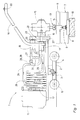
- a screwing machine 1 shown in FIG. 1 has a frame 2 which is movably connected via a joint 3 to a chassis 4 both about a vertical axis and about a horizontal axis running in the transverse direction of the track.
- This undercarriage 4 can be rolled off on a rail 6 of a track 7 via two double track roller wheels 5.
- the rails 6 rest on rib plates 8 and are connected to sleepers 10 by means of rail fastening screws 9.
- a motor 11 designed as an internal combustion engine
- a hydraulic pump 12 in the form of a gear pump, which are arranged on one longitudinal end of the frame 2 for reasons of balance.
- a screw head 13 which has a vertical screw spindle 14 and is connected via an angular gear 15 to a horizontally running drive shaft 16 of a first oil motor 17.
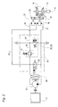
- the angular gear 15 is equipped with a turning stage which enables the direction of rotation of the screw spindle 14 to be reversed (see FIG. 2).
- a bracket 18 is used for manual lifting or lowering and lateral pivoting of the end of the frame 2 having the screw head 13 around the joint 3.
- a second oil motor 19 is provided for optional additional torque transmission to the screw head 13 and is connected to a housing 20 of a transmission 21.
- This single-stage gear 21 has a freewheel 22 which is arranged coaxially to the drive shaft 16 and which is in permanent engagement with a drive pinion 23 of the second oil motor 19 and allows the drive shaft 16 to rotate independently of the gear 21 through the first oil motor 17.
- the two oil motors 17, 19 can be acted upon by the hydraulic pump 12 via a working line 24 and are further connected to a return line 25, which is partially in the form of a cooling coil 26.
- the suction side of the second oil motor 19 is connected to the working line 24 (and thus to the hydraulic pump 12) via a supply line 27 in which a cut-in valve 28 is arranged.
- This is designed as a pilot-operated pressure relief valve 29, which is activated or opened when a predetermined pressure in the working line 24 is reached.
- the supply line 27 is connected to the return line 25 via a line 30 which contains a pressure control valve 31. This is also pre-controlled and switches to circulation when a predetermined pressure in the feed line 27 is reached.
- a magnetically controlled circulation valve 32 is provided between the working line 24 and the return line 25, with which (according to the position of the valve shown here) both oil motors 17, 19 can be taken out of operation while the hydraulic pump 12 is running.
- the screw spindle 14 is placed on the screw using the bracket 18. Then, by closing the circulation valve 32 via an operating switch 33, the first oil motor 17 is acted upon via the working line 24 (with the connecting valve 28 closed). Due to the free running of the transmission 21, the second oil motor 19 is not positively coupled to the drive shaft 16. The first oil motor 17 now drives the screw spindle 14 at high speed, with only very little resistance being provided by the screw in this first screw-in phase. However, once the screw is tightened, there is an increase in the pressure in the working line 24 as a result of the higher torque now required.
- the pilot-operated cut-in valve 28 or pressure-limiting valve 29 opens automatically, and the second oil motor 19 is acted upon in parallel to the first oil motor 17. Due to the presence of the gear 21 with the freewheel, there is automatically a force compensation between the two oil motors 17 and 19, which results in a second, slower rotational speed with a correspondingly higher torque transmitted to the drive shaft 16, with which the screw in the desired end position is tightened. Reaching the same is signaled by the pressure in the hydraulic system rising to a predetermined value, at which the pressure control valve 31 is activated and - by automatically switching over to circulation - the oil motors 17, 19 are put out of operation. This completes the screwing process without any action by the operator.
Abstract
Description
Die Erfindung betrifft eine Schraubmaschine zum Eindrehen und Lösen von Schienenbefestigungsschrauben und -muttern, mit einem Motor zur Energieerzeugung, einer Hydraulikpumpe, einem mit dieser über eine Arbeitsleitung in Verbindung stehenden Ölmotor, einem von diesem über eine Antriebswelle antreibbaren Schraubkopf sowie einem Druckregelventil.The invention relates to a screwing machine for screwing in and loosening rail fastening screws and nuts, with a motor for generating energy, a hydraulic pump, an oil motor connected to the latter via a working line, a screw head which can be driven by the drive shaft, and a pressure control valve.
Eine derartige, durch die DE 29 43 938 A1 bekannte hydraulische Schraubmaschine weist eine regelbare Hydraulikpumpe und einen koaxial mit einem Schraubkopf verbundenen, diesen direkt antreibenden Ölmotor auf. Anhand eines Fördermengenreglers ist der Ölstrom stufenlos einstellbar, wobei ein Druckregler bei Erreichen eines gewünschten Druckes die Pumpe zur Vermeidung von Drehmomentspitzen auf Umlauf schaltet. Beim Anziehen von Schrauben erfolgt die erste Schraubphase mit hoher Drehgeschwindigkeit und geringem Moment, das langsame Ansteuern der genauen Endlage hingegen mit hohem Drehmoment. Bedingt durch das besonders beim Ausdrehen der Schienenbefestigungsmittel notwendige hohe Drehmoment und die entsprechende Dimensionierung der Hydraulikanlage samt großem Tank ist diese Maschine durch das relativ hohe Gewicht unhandlich.Such a hydraulic screwing machine known from DE 29 43 938 A1 has an adjustable hydraulic pump and an oil motor which is connected coaxially to a screwing head and drives it directly. The oil flow is infinitely adjustable with the aid of a flow rate regulator, whereby a pressure regulator switches the pump to circulation to avoid torque peaks when a desired pressure is reached. When tightening screws, the first screwing phase takes place at high rotational speed and low torque, while the slow control of the exact end position takes place with high torque. Due to the high torque required when unscrewing the rail fasteners and the appropriate dimensioning of the hydraulic system including the large tank, this machine is bulky due to the relatively high weight.
Eine weitere Schraubmaschine ist durch einen Prospekt "Universal-Schraubmaschine Robel 30.82 mit hydraulischer Drehmoment-Feinsteuerung" der Firma Robel bekannt. Diese an und für sich mechanisch über einen Verbrennungsmotor und ein Getriebe mit metallener Kupplung angetriebene Maschine ist zusätzlich mit einer zuschaltbaren Hydraulikanlage für eine exakte Steuerung des Drehmoments ausgestattet. Im Anschluß an das schnelle mechanische Vorschrauben wird das genaue bzw. gewünschte, endgültige Drehmoment mit hydraulischer Unterstützung erzielt. Diese Maschine ist ebenfalls eher schwer und daher ergonomisch ungünstig in der Handhabung.Another screwing machine is known from a brochure "Robel 30.82 universal screwing machine with hydraulic torque fine control" from Robel. This machine, which is mechanically driven by an internal combustion engine and a gearbox with a metal clutch, is additionally equipped with a switchable hydraulic system for precise control of the torque. Following the fast mechanical pre-screwing, the precise or desired, final torque is achieved with hydraulic support. This machine is also rather heavy and therefore ergonomically unfavorable to use.
Die Aufgabe der vorliegenden Erfindung besteht nun in der Schaffung einer Maschine der eingangs beschriebenen Art, die unter Beibehaltung eines hydraulischen Antriebes besonders handlich und leicht manövrierbar ausgebildet ist.The object of the present invention is to provide a machine of the type described in the introduction, which is designed to be particularly handy and easy to maneuver while maintaining a hydraulic drive.
Diese Aufgabe wird mit der gattungsgemäßen Schraubmaschine dadurch gelöst, daß zusätzlich zum genannten ersten Ölmotor ein zweiter Ölmotor vorgesehen ist, der über ein Zuschaltventil und ein Getriebe zur wahlweisen zusätzlichen Drehmomentübertragung auf den Schraubkopf ausgebildet ist.This object is achieved with the generic screwing machine in that, in addition to the first oil motor mentioned, a second oil motor is provided, which is designed via a cut-in valve and a gear for optional additional torque transmission to the screwing head.
Eine derart ausgebildete Schraubmaschine bietet den Vorteil, daß das Gewicht der Maschine gering gehalten werden kann, da es durch das Zuschaltventil möglich ist, beide Ölmotoren mit nur einem einzigen Hydraulikkreislauf bzw. nur einer Pumpe zu betreiben. Ebenso gewichtssparend wirkt sich auch das Fehlen einer mechanischen Kupplung aus. Diese ist bei der erfindungsgemäßen Maschine hinfällig, da das Umschalten zwischen der schnellen Vorschraubgeschwindigkeit und der langsamen Schlußphase allein durch Betätigung des Zuschaltventiles erreicht werden kann. So ist auf besonders einfache Art und Weise der gewünschte Effekt erzielbar, den Schraubvorgang mit hohem Drehmoment beenden zu können, da sich dieses hohe Moment bzw. die damit einhergehende langsame Drehgeschwindigkeit automatisch durch den Druckausgleich im System nach Öffnen des Zuschaltventiles einstellt.A screwing machine designed in this way has the advantage that the weight of the machine can be kept low, since it is possible through the connecting valve to operate both oil motors with only a single hydraulic circuit or only one pump. The lack of a mechanical coupling also has a weight-saving effect. This does not apply to the machine according to the invention, since the switchover between the fast screwing speed and the slow closing phase can be achieved solely by actuating the connection valve. In this way, the desired effect of being able to end the screwing process with high torque can be achieved in a particularly simple manner, since this high torque or the associated slow rotational speed is automatically set by the pressure compensation in the system after opening the connection valve.
Die Ausbildung gemäß Anspruch 2 mit dem Freilauf des Getriebes ermöglicht unterdessen den Einsatz lediglich des ersten Ölmotors mit hoher Geschwindigkeit bzw. geringem Drehmoment, um die erste Phase des Schraubeneindrehens so rasch als möglich zu absolvieren.The design according to
Die Weiterbildung nach Anspruch 3 schafft - in Verbindung mit dem Druckregelventil - den Vorteil, daß der gesamte Arbeitszyklus bis hin zum Erreichen des exakten Anzugsmomentes vollautomatisch, d.h. ohne Schalten oder andere Handlungen seitens einer Bedienungsperson, ablaufen kann. Die beiden unterschiedlichen Schraubgeschwindigkeiten stellen sich selbsttätig gemäß der Stellung des Druckbegrenzungsventils ein, welches sich aufgrund der Vorsteuerung bei Erreichen eines bestimmten Druckes automatisch öffnet. Desgleichen schaltet das ebenfalls vorgesteuerte Druckregelventil automatisch auf Umlauf, sobald durch den ansteigenden Widerstand der Druck im Hydrauliksystem über einen bestimmten, das gewünschte Drehmoment signalisierenden Wert ansteigt.The development according to
Weitere erfindungsgemäße Vorteile ergeben sich aus Unteransprüchen und Beschreibung.Further advantages according to the invention result from subclaims and description.
Die Erfindung wird im folgenden anhand von Zeichnungen näher beschrieben, wobei
- Fig. 1 eine Seitenansicht einer erfindungsgemäß mit zwei Ölmotoren ausgebildeten Schraubmaschine und
- Fig. 2 den zugehörigen schematischen Schaltplan des Hydraulikkreislaufes zeigt.
- Fig. 1 is a side view of a screwing machine designed according to the invention with two oil motors and
- Fig. 2 shows the associated schematic circuit diagram of the hydraulic circuit.
Eine in Fig. 1 ersichtliche Schraubmaschine 1 weist einen Rahmen 2 auf, der über ein Gelenk 3 mit einem Fahrgestell 4 sowohl um eine vertikale als auch um eine in Gleisquerrichtung verlaufende, horizontale Achse beweglich verbunden ist. Dieses Fahrgestell 4 ist über zwei Doppelspurkranzrollen 5 auf einer Schiene 6 eines Gleises 7 abrollbar. Die Schienen 6 ruhen auf Rippenplatten 8 und sind anhand von Schienenbefestigungsschrauben 9 mit Schwellen 10 verbunden.A screwing machine 1 shown in FIG. 1 has a
Auf dem Rahmen 2 sind ein - als Verbrennungsmotor ausgebildeter - Motor 11 und eine Hydraulikpumpe 12 in Form einer Zahnradpumpe befestigt, die aus Balancegründen am einen Längsende des Rahmens 2 angeordnet sind. Am gegenüberliegenden Ende des Rahmens befindet sich ein eine senkrecht stehende Schraubspindel 14 aufweisender Schraubkopf 13, der über ein Winkelgetriebe 15 mit einer waagrecht verlaufenden Antriebswelle 16 eines ersten Ölmotors 17 verbunden ist. Das Winkelgetriebe 15 ist mit einer Wendestufe ausgestattet, die ein Umkehren der Drehrichtung der Schraubspindel 14 ermöglicht (siehe Fig.2). Ein Bügel 18 dient zum manuellen Heben bzw. Senken und Seitenverschwenken des den Schraubkopf 13 aufweisenden Endes des Rahmens 2 um das Gelenk 3.Mounted on the
Parallel zum ersten Ölmotor 17 ist - zur wahlweisen zusätzlichen Drehmomentübertragung auf den Schraubkopf 13 - ein zweiter Ölmotor 19 vorgesehen, der mit einem Gehäuse 20 eines Getriebes 21 verbunden ist. Dieses einstufig ausgebildete Getriebe 21 weist ein koaxial zur Antriebswelle 16 angeordnetes Freilaufrad 22 auf, welches mit einem Antriebsritzel 23 des zweiten Ölmotors 19 in permanentem Eingriff steht und eine vom Getriebe 21 unabhängige Rotation der Antriebswelle 16 durch den ersten Ölmotor 17 gestattet. Die beiden Ölmotoren 17,19 sind über eine Arbeitsleitung 24 von der Hydraulikpumpe 12 beaufschlagbar und sind weiters an eine Rückflußleitung 25 angeschlossen, die teilweise in Form einer Kühlschlange 26 ausgebildet ist.In parallel to the
Wie nun auch anhand der Fig. 2 genauer zu erkennen, ist die Saugseite des zweiten Ölmotors 19 mit der Arbeitseitung 24 (und somit der Hydraulikpumpe 12) über eine Zuleitung 27 verbunden, in der ein Zuschaltventil 28 angeordnet ist. Dieses ist als vorgesteuertes Druckbegrenzungsventil 29 ausgebildet, das bei Erreichen eines vorbestimmten Druckes in der Arbeitsleitung 24 aktiviert bzw. geöffnet wird. Die Zuleitung 27 steht mit der Rückflußleitung 25 über eine Leitung 30 in Verbindung, die ein Druckregelventil 31 beinhaltet. Dieses ist ebenfalls vorgesteuert und schaltet bei Erreichen eines vorbestimmten Druckes in der Zuleitung 27 auf Umlauf. Zusätzlich ist noch zwischen Arbeitsleitung 24 und Rückflußleitung 25 ein magnetisch gesteuertes Umlaufventil 32 vorgesehen, mit dem (gemäß der hier gezeigten Stellung des Ventils) beide Ölmotoren 17,19 bei laufender Hydraulikpumpe 12 außer Betrieb genommen werden können.As can now also be seen more clearly from FIG. 2, the suction side of the
Zu Beginn eines Arbeitseinsatzes zum Eindrehen von Schienenbefestigungsschrauben 9 bzw. Muttern wird die Schraubspindel 14 anhand des Bügels 18 auf die Schraube aufgesetzt. Danach erfolgt durch Schließen des Umlaufventiles 32 über einen Bedienungsschalter 33 ein Beaufschlagen des ersten Ölmotors 17 über die Arbeitseitung 24 (bei geschlossenem Zuschaltventil 28). Durch den Freilauf des Getriebes 21 ist der zweite Ölmotor 19 hierbei formschlüssig nicht an die Antriebswelle 16 gekoppelt. Der erste Ölmotor 17 treibt nun die Schraubspindel 14 mit hoher Geschwindigkeit an, wobei in dieser ersten Einschraubphase von der Schraube nur sehr geringer Widerstand entgegengebracht wird. Sobald die Schraube jedoch fester angezogen ist, kommt es zu einem Ansteigen des Druckes in der Arbeitsleitung 24 infolge des nun erforderlichen höheren Drehmomentes. Bei Erreichen eines Druckes von 120 bar in der Arbeitsleitung 24 öffnet das vorgesteuerte Zuschaltventil 28 bzw. Druckbegrenzungsventil 29 selbsttätig, und der zweite Ölmotor 19 wird parallel zum ersten Ölmotor 17 beaufschlagt. Dabei erfolgt, bedingt durch das Vorhandensein des Getriebes 21 mit dem Freilauf, automatisch ein kraftmäßiger Ausgleich zwischen den beiden Ölmotoren 17 und 19, der in einer zweiten, langsameren Drehgeschwindigkeit mit dementsprechend höherem, auf die Antriebswelle 16 übertragenen Drehmoment resultiert, mit dem die Schraube in die gewünschte Endstellung festgezogen wird. Das Erreichen derselben wird durch das Ansteigen des Druckes im Hydrauliksystem auf einen vorbestimmten Wert signalisiert, bei dem das Druckregelventil 31 aktiviert wird und - durch automatisches Umschalten auf Umlauf - die Ölmotoren 17,19 außer Betrieb nimmt. Hiermit wird der Schraubvorgang beendet, ohne daß dazu irgendeine Handlung der Bedienungsperson erforderlich wäre.At the beginning of a work assignment for screwing in rail fastening
Claims (4)
Applications Claiming Priority (2)
| Application Number | Priority Date | Filing Date | Title |
|---|---|---|---|
| DE19532826 | 1995-09-06 | ||
| DE19532826A DE19532826A1 (en) | 1995-09-06 | 1995-09-06 | Screwdriver |
Publications (1)
| Publication Number | Publication Date |
|---|---|
| EP0761881A1 true EP0761881A1 (en) | 1997-03-12 |
Family
ID=7771364
Family Applications (1)
| Application Number | Title | Priority Date | Filing Date |
|---|---|---|---|
| EP96111876A Withdrawn EP0761881A1 (en) | 1995-09-06 | 1996-07-24 | Screwing machine |
Country Status (8)
| Country | Link |
|---|---|
| EP (1) | EP0761881A1 (en) |
| BG (1) | BG100833A (en) |
| CZ (1) | CZ252896A3 (en) |
| DE (1) | DE19532826A1 (en) |
| HR (1) | HRP960408A2 (en) |
| HU (1) | HUP9602420A2 (en) |
| PL (1) | PL315923A1 (en) |
| SK (1) | SK113896A3 (en) |
Cited By (4)
| Publication number | Priority date | Publication date | Assignee | Title |
|---|---|---|---|---|
| WO2006031168A1 (en) * | 2004-09-17 | 2006-03-23 | Rosenqvist Rail Tech Ab | An arrangement that can be readily manoeuvred. |
| WO2006058552A1 (en) * | 2004-12-03 | 2006-06-08 | Robel Bahnbaumaschinen Gmbh | Coach screw driver |
| EP1983230A1 (en) * | 2007-04-18 | 2008-10-22 | NAF Neunkirchener Achsenfabrik AG | Transmission device for a motor vehicle and motor vehicle |
| WO2015118334A3 (en) * | 2014-02-05 | 2015-11-19 | Forum Energy Technologies (Uk) Limited | Torque tool, motor assembly, and methods of use |
Citations (4)
| Publication number | Priority date | Publication date | Assignee | Title |
|---|---|---|---|---|
| FR1533959A (en) * | 1967-06-12 | 1968-07-26 | Ind De La Varenne | Machine for screwing and unscrewing railway lag bolts |
| DE2943938A1 (en) * | 1979-10-31 | 1981-05-14 | Georg Robel GmbH & Co, 8000 München | Hydraulic machine for tightening bolts of railway sleepers - has flow regulator to reduce energy losses in hydraulic circuit |
| EP0169753A2 (en) * | 1984-07-27 | 1986-01-29 | Societe Turripinoise De Mecanique (S.A.R.L.) | Drive mechanism for the tool-carrying spindle of a sleeper-screwing machine |
| DE9407064U1 (en) * | 1994-04-28 | 1994-10-20 | Robel Georg Gmbh & Co | Screwdriver |
-
1995
- 1995-09-06 DE DE19532826A patent/DE19532826A1/en not_active Withdrawn
-
1996
- 1996-07-24 EP EP96111876A patent/EP0761881A1/en not_active Withdrawn
- 1996-08-28 CZ CZ962528A patent/CZ252896A3/en unknown
- 1996-09-02 PL PL96315923A patent/PL315923A1/en unknown
- 1996-09-04 HU HU9602420A patent/HUP9602420A2/en unknown
- 1996-09-04 SK SK1138-96A patent/SK113896A3/en unknown
- 1996-09-06 HR HR19532826.4A patent/HRP960408A2/en not_active Application Discontinuation
- 1996-09-06 BG BG100833A patent/BG100833A/en unknown
Patent Citations (4)
| Publication number | Priority date | Publication date | Assignee | Title |
|---|---|---|---|---|
| FR1533959A (en) * | 1967-06-12 | 1968-07-26 | Ind De La Varenne | Machine for screwing and unscrewing railway lag bolts |
| DE2943938A1 (en) * | 1979-10-31 | 1981-05-14 | Georg Robel GmbH & Co, 8000 München | Hydraulic machine for tightening bolts of railway sleepers - has flow regulator to reduce energy losses in hydraulic circuit |
| EP0169753A2 (en) * | 1984-07-27 | 1986-01-29 | Societe Turripinoise De Mecanique (S.A.R.L.) | Drive mechanism for the tool-carrying spindle of a sleeper-screwing machine |
| DE9407064U1 (en) * | 1994-04-28 | 1994-10-20 | Robel Georg Gmbh & Co | Screwdriver |
Cited By (6)
| Publication number | Priority date | Publication date | Assignee | Title |
|---|---|---|---|---|
| WO2006031168A1 (en) * | 2004-09-17 | 2006-03-23 | Rosenqvist Rail Tech Ab | An arrangement that can be readily manoeuvred. |
| WO2006058552A1 (en) * | 2004-12-03 | 2006-06-08 | Robel Bahnbaumaschinen Gmbh | Coach screw driver |
| EA010555B1 (en) * | 2004-12-03 | 2008-10-30 | Робел Банбаумашинен Гмбх | Coach screw driver |
| EP1983230A1 (en) * | 2007-04-18 | 2008-10-22 | NAF Neunkirchener Achsenfabrik AG | Transmission device for a motor vehicle and motor vehicle |
| WO2015118334A3 (en) * | 2014-02-05 | 2015-11-19 | Forum Energy Technologies (Uk) Limited | Torque tool, motor assembly, and methods of use |
| AU2015213892B2 (en) * | 2014-02-05 | 2019-04-18 | Forum Energy Technologies (Uk) Limited | Torque tool, motor assembly, and methods of use |
Also Published As
| Publication number | Publication date |
|---|---|
| DE19532826A1 (en) | 1997-03-13 |
| PL315923A1 (en) | 1997-03-17 |
| CZ252896A3 (en) | 1997-03-12 |
| HUP9602420A2 (en) | 1997-05-28 |
| BG100833A (en) | 1997-10-31 |
| HRP960408A2 (en) | 1997-08-31 |
| HU9602420D0 (en) | 1996-11-28 |
| SK113896A3 (en) | 1997-04-09 |
Similar Documents
| Publication | Publication Date | Title |
|---|---|---|
| DE3331211C2 (en) | ||
| EP0936175A1 (en) | Escalator drive | |
| EP0761881A1 (en) | Screwing machine | |
| DE10255079A1 (en) | A friction gear for a separate auxiliary unit assigned to an aggregate belt drive of an internal combustion engine | |
| DE2732987A1 (en) | DRILL WITH ROTARY DRIVE CONTROL | |
| EP2260210B1 (en) | Controller and the use thereof | |
| EP0873901A2 (en) | Drive for a mobile working apparatus | |
| DE2943938A1 (en) | Hydraulic machine for tightening bolts of railway sleepers - has flow regulator to reduce energy losses in hydraulic circuit | |
| DD207517B1 (en) | DEVICE FOR POSITIONING TO PRINTING MACHINES | |
| EP0246631A1 (en) | Ship's propulsion unit | |
| EP0761882B1 (en) | Machine used in railway track work | |
| DD135876B1 (en) | DRIVE ARRANGEMENT, ESPECIALLY FOR INJECTION MOLDING MACHINES | |
| DE112019008009T5 (en) | VALVE ACTUATOR | |
| DE3814211C1 (en) | Drive mechanism for a twin-screw extruder | |
| DD200234A1 (en) | METHOD FOR CONTROLLING DRIVE MOTOR AND DRIVE DRIVE IN SELF-OPERATING WORKING MACHINES | |
| DE420488C (en) | Table drive for tools, especially for grinding machines | |
| DE102007043376A1 (en) | Drive device with torque compensation | |
| DE503579C (en) | Machine tool with a machine part that performs two movements at the same time | |
| DE956311C (en) | Control device for traction vehicles that are driven by means of an internal combustion engine and continuously adjustable friction gear | |
| DE708853C (en) | Step switching device, especially for transformers, with tensioning Maltese cross gear | |
| EP0784174A2 (en) | Armature with and electromotor actuator | |
| DE709501C (en) | Adjusting device for the rolls of rolling mills | |
| DE460773C (en) | Procedure for starting diesel locomotives and similar vehicles | |
| DE313784C (en) | ||
| DE2163895C3 (en) | Switching device for a hydrostatic creeper drive in commercial vehicles |
Legal Events
| Date | Code | Title | Description |
|---|---|---|---|
| PUAI | Public reference made under article 153(3) epc to a published international application that has entered the european phase |
Free format text: ORIGINAL CODE: 0009012 |
|
| 17P | Request for examination filed |
Effective date: 19960821 |
|
| AK | Designated contracting states |
Kind code of ref document: A1 Designated state(s): AT BE CH DE DK ES FR GB IT LI NL SE |
|
| 17Q | First examination report despatched |
Effective date: 19971021 |
|
| STAA | Information on the status of an ep patent application or granted ep patent |
Free format text: STATUS: THE APPLICATION IS DEEMED TO BE WITHDRAWN |
|
| 18D | Application deemed to be withdrawn |
Effective date: 19980303 |